Thinking big right from the smallest things: Donelli Alexo’s FBE and TSA coatings for critical assets in highly corrosive environments
page 12
The GIANT project: revolutionizing cathodic protection through AI-driven optimization page 30
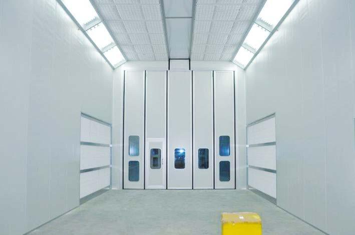
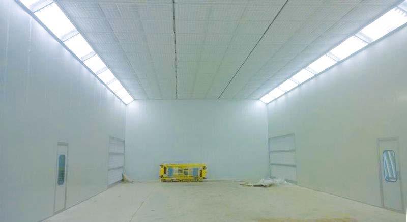
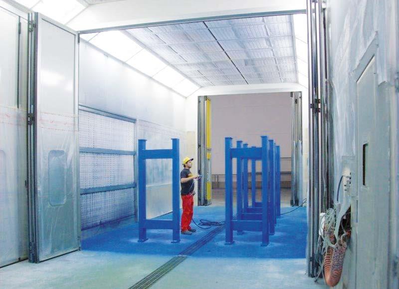
Painting large-sized components? Eco Air booths make it possible page 62
“WITHOUT A SHADOW OF DOUBT, OF SAYING THEY CAN DO ANYTHING, FUTURE WE WILL SEE IF THEY
“SICURAMENTE
TUTTI SONO CHE DICONO DI SAPER FARE, SE È STATO FATTO E COME
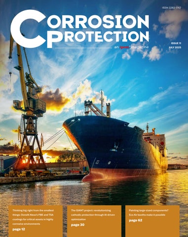
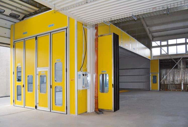
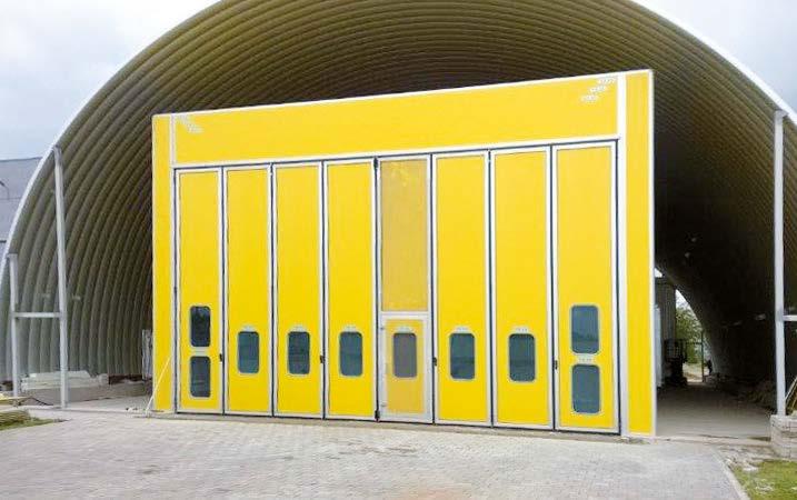
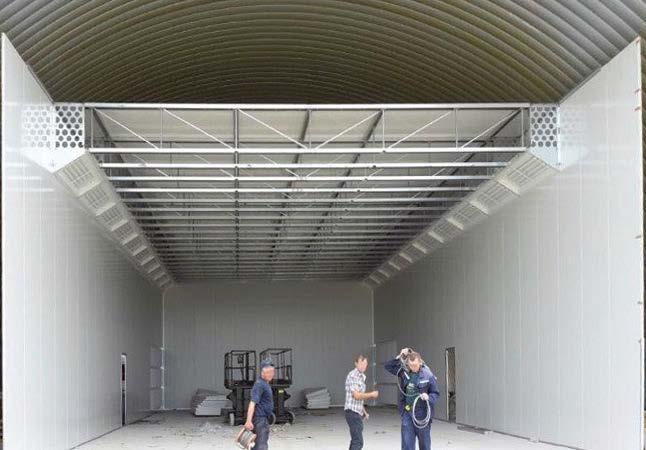
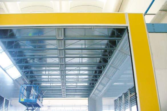
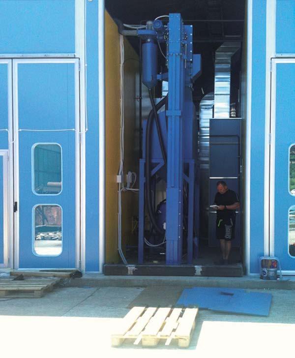
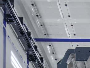
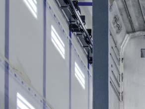
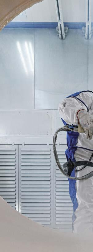
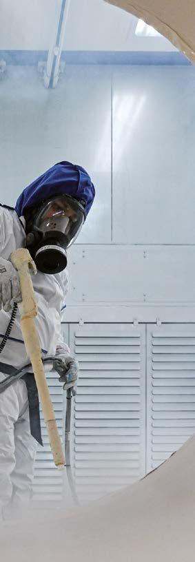
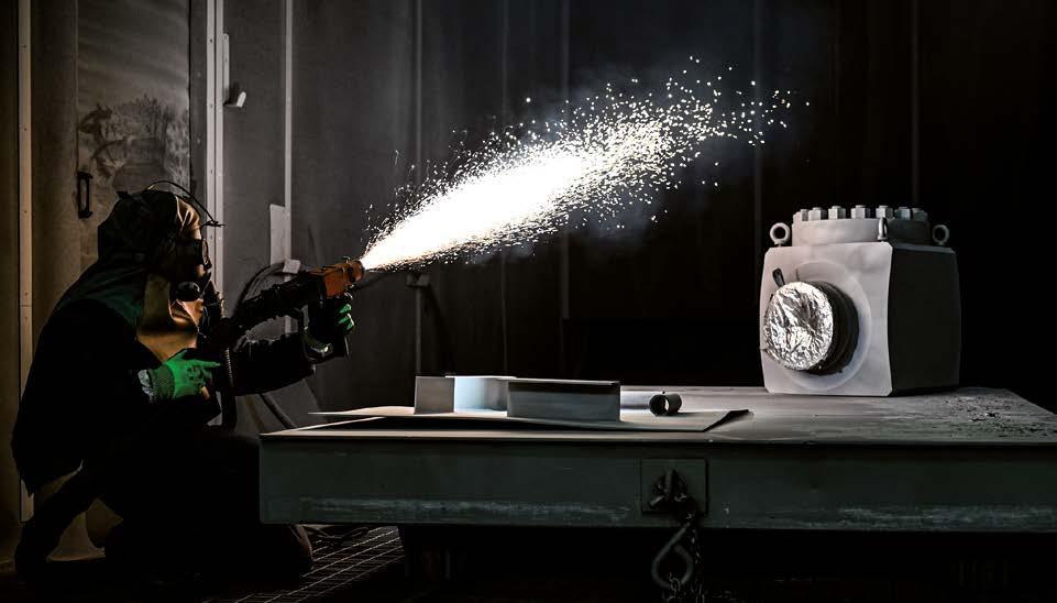
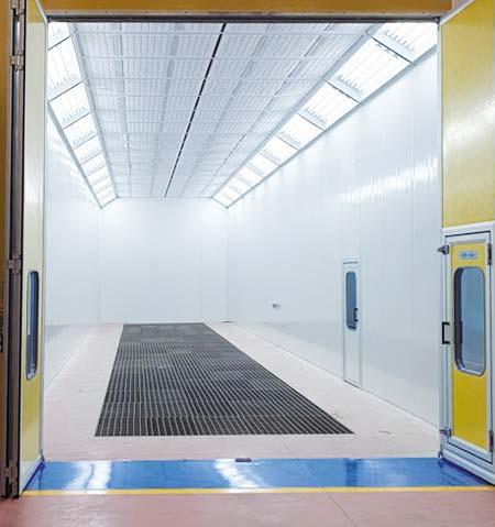
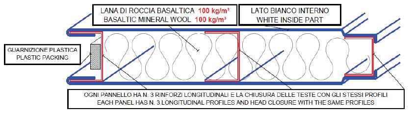
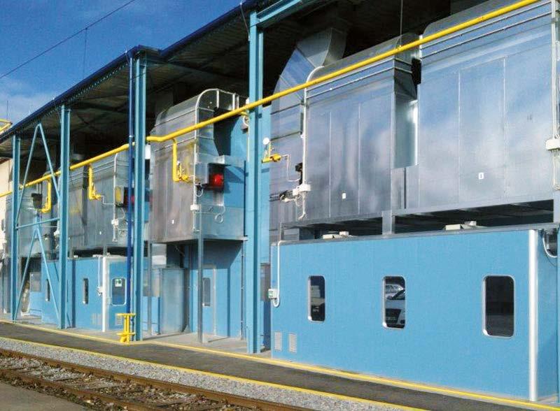
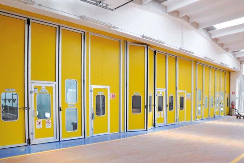
COATING BOOTHS FOR LARGE-SIZED COMPONENTS
CABINE DI VERNICIATURA PER COMPONENTI DI GRANDI
11-13 NOV. 2025, KUALA LUMPUR, MALAYSIA
12
Thinking big right from the smallest things: Donelli Alexo’s FBE and TSA coatings for critical assets in highly corrosive environments
20 ADVANCEMENTS
Make lube point a touch point for corrosion protection
22 COVER STORY
When the paint supplier’s technical support is key to the high performance of protective coatings for electrical transformers
30 SCIENCE OUTLOOK
The GIANT project: revolutionizing cathodic protection through AI-driven optimization
38 AROUND THE WORLD
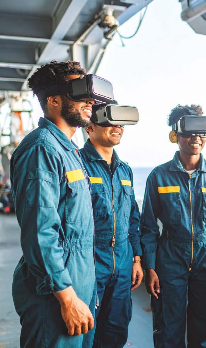
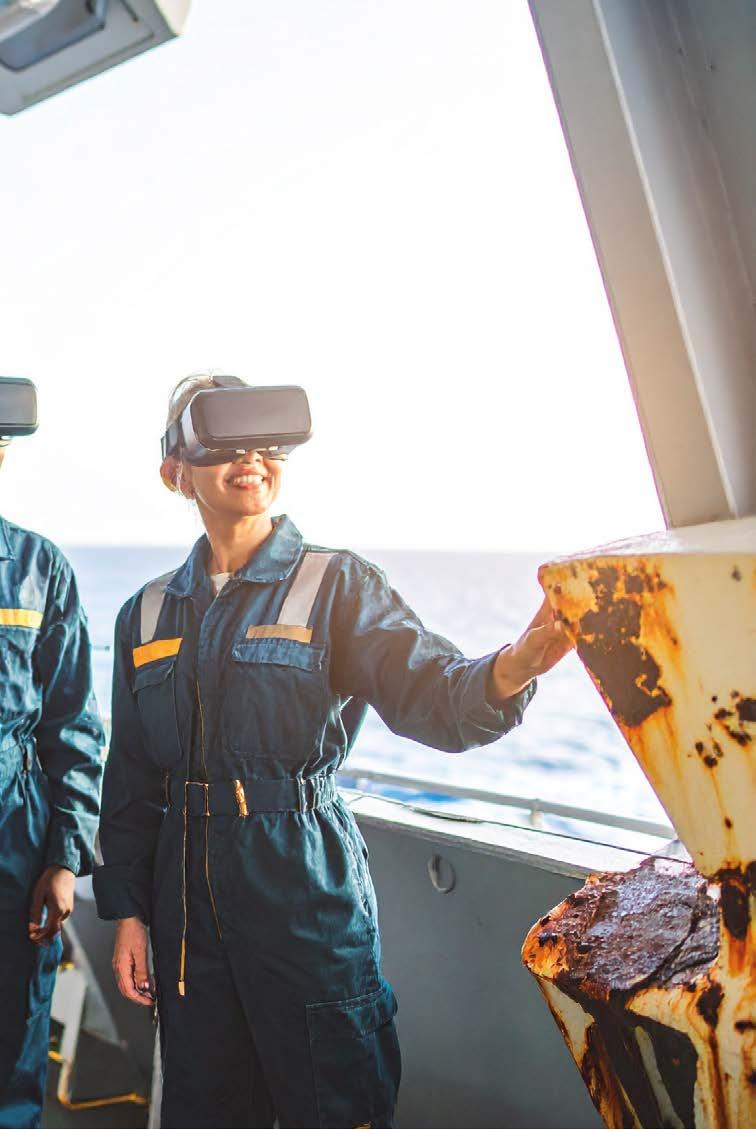
Naval Surface Warfare Center taps Clemson University to develop virtual reality-based corrosion training for sailors
42 ADVANCEMENTS
Novel calcium silicate-based anti-corrosive pigments for superior anti-corrosion performance
46 SPOTLIGHT
Celebrating 50 years of flame retardants: Exolit™ AP leads the way to a more sustainable future
50 SUCCESS STORY
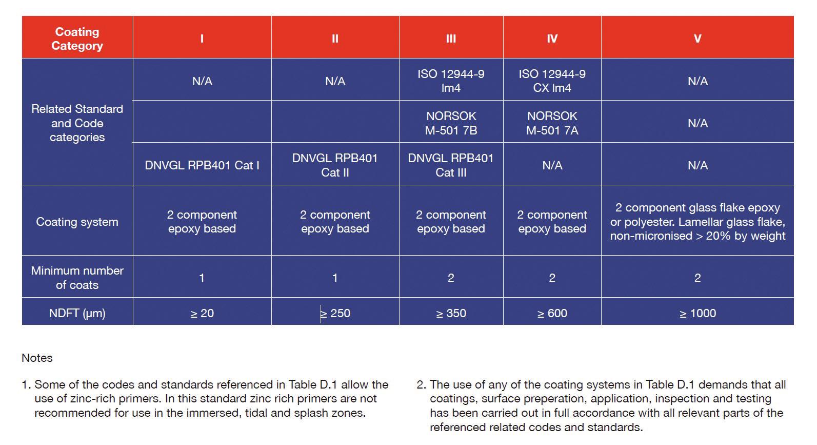
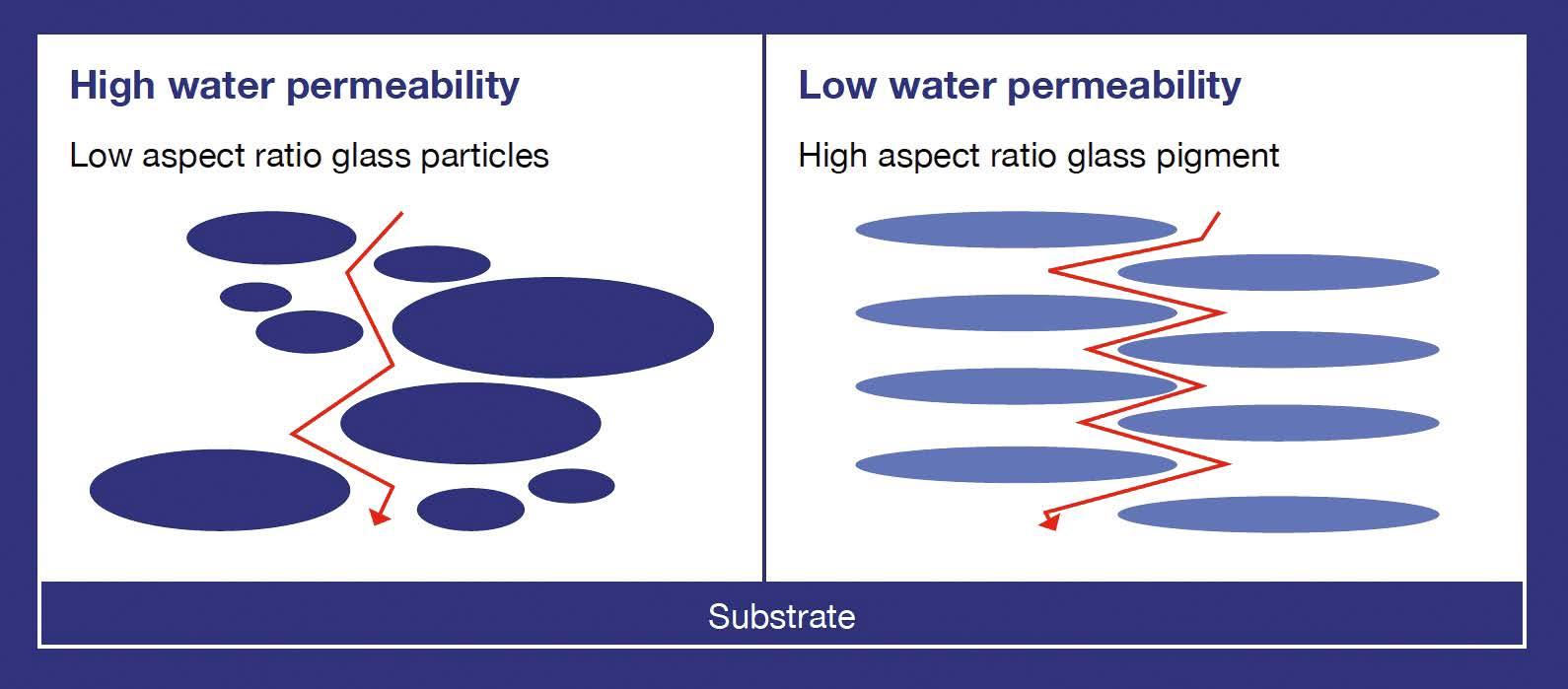
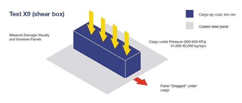
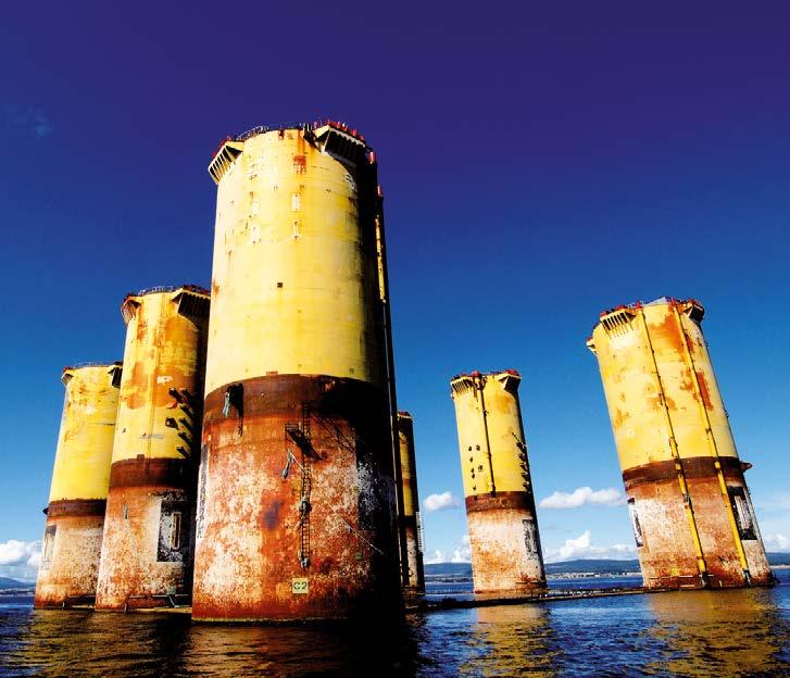
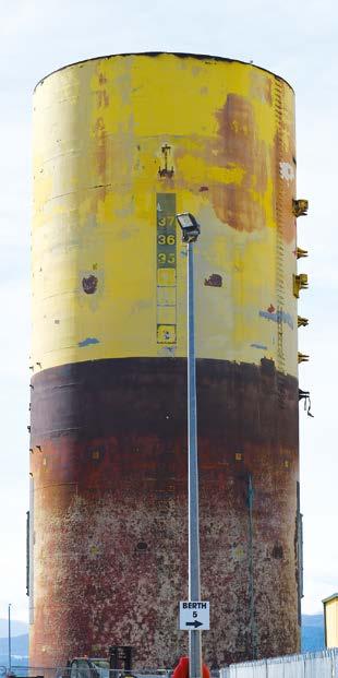
40 years of performance Hutton TLP case study and the impact of highly loaded lamellar glass flake in offshore coating
62 SPOTLIGHT
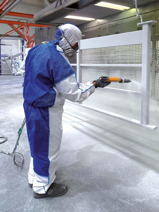
Painting large-sized components?
Eco Air booths make it possible
66 SCIENCE OUTLOOK
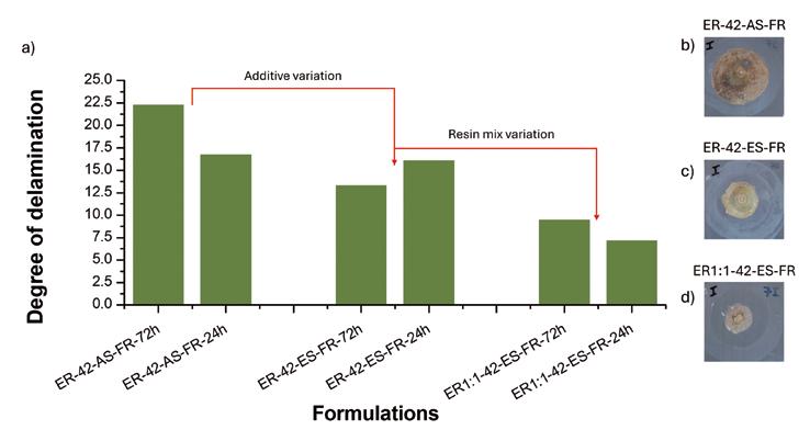
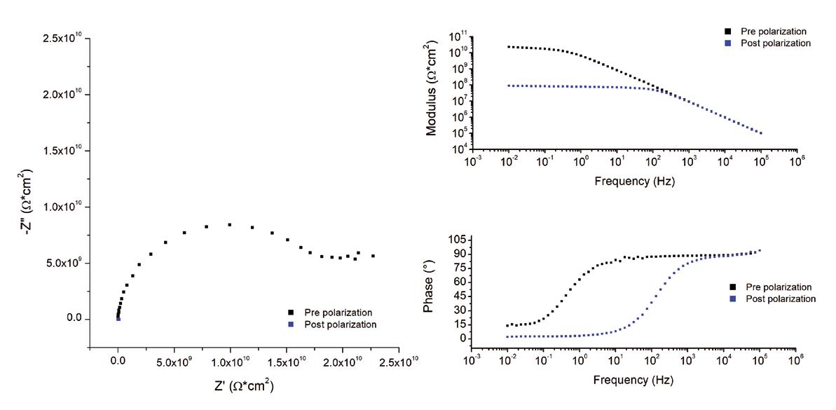
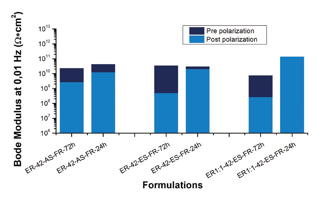
Evaluation of delamination resistance and corrosion protection in fouling release coatings for bronze propellers
76 SPOTLIGHT
Adapting to shifting seas: how Jotun reinvents
Hull Performance Solutions
80 SCIENCE OUTLOOK
Comparing cathodic protection systems: wind offshore vs. oil jackets
84 MEETING THE INDUSTRY
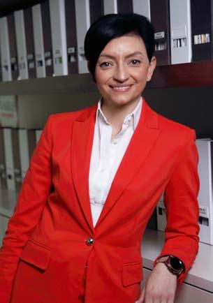
Alessia Venturi
Editor-in-chief
EDITOR FROM THE
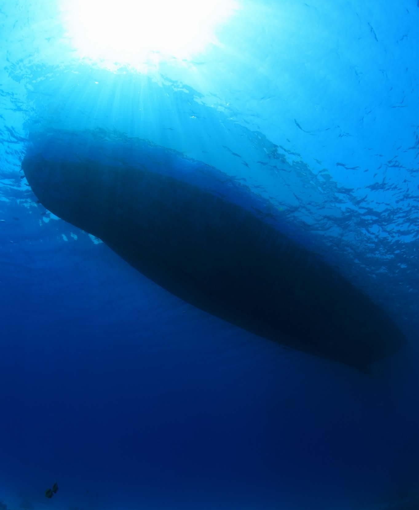
Can the sea be considered infrastructure?
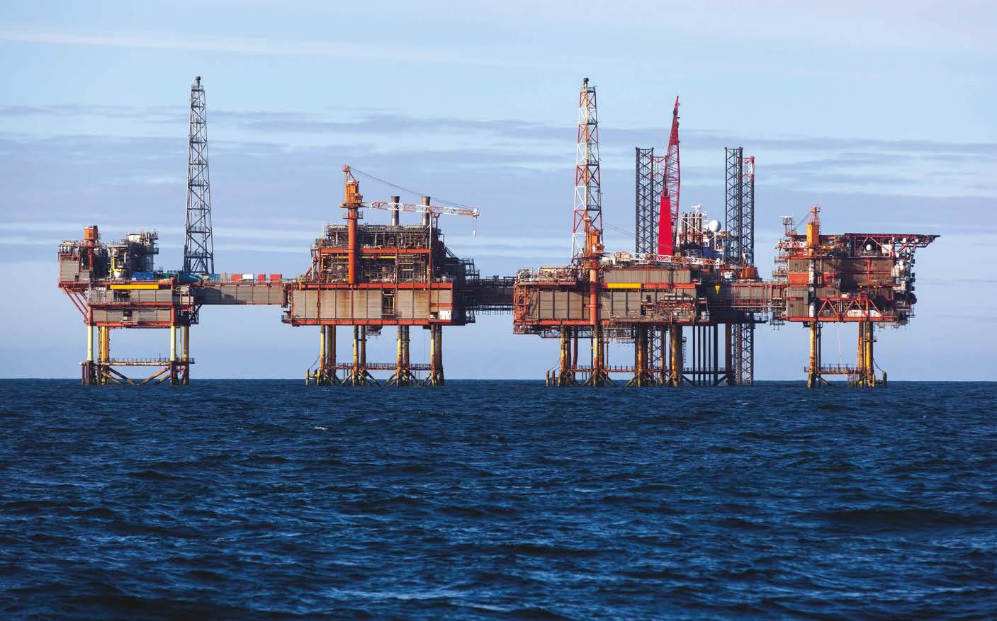
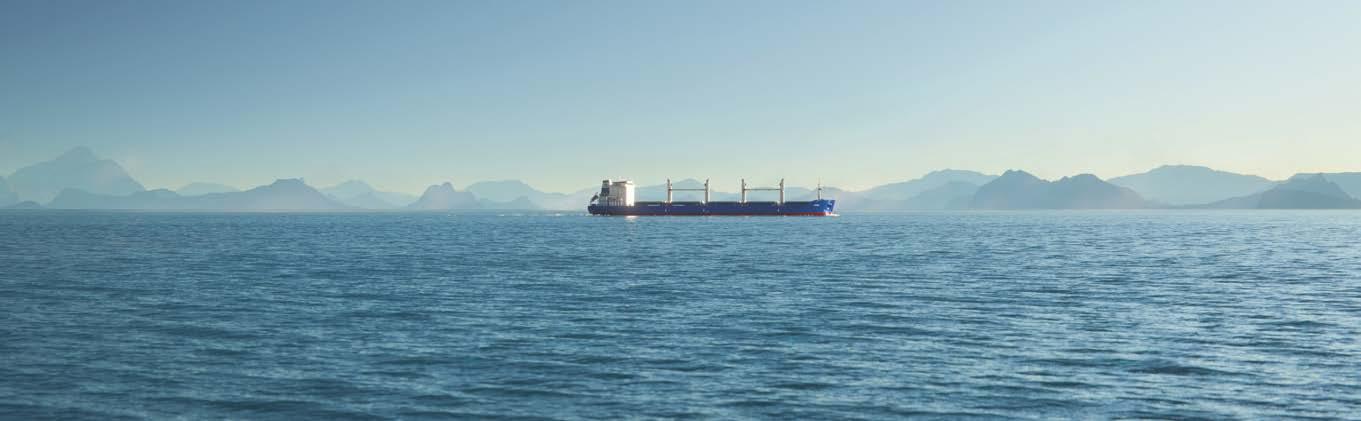
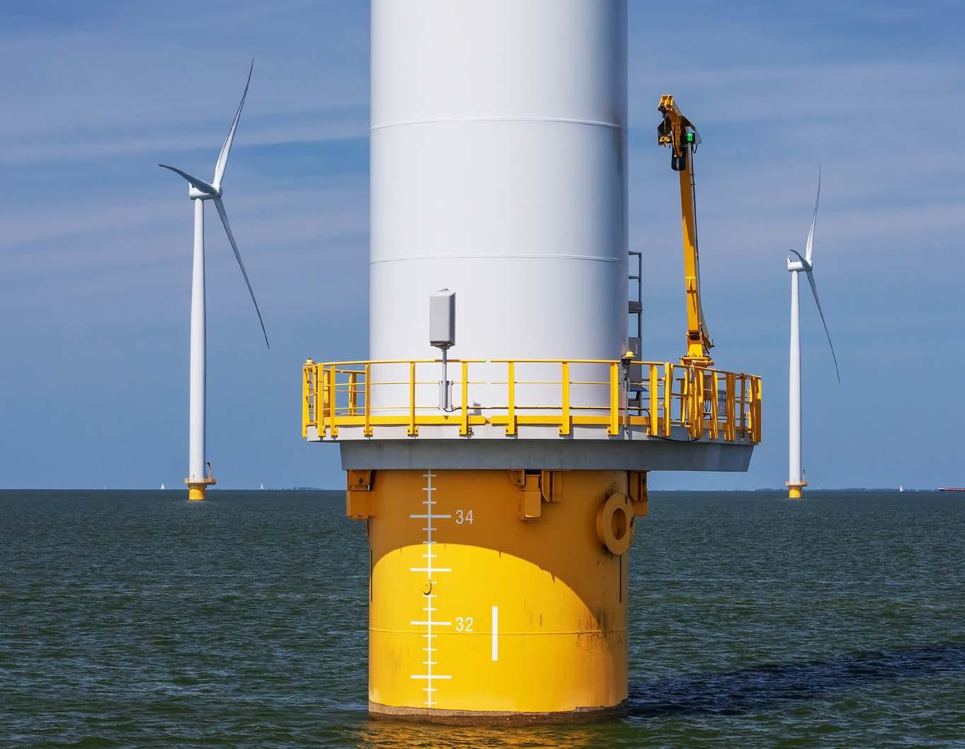
While offshore platforms and cargo and merchant ships have long been a part of many coastal countries’ seascapes, offshore wind farms are a more recent addition, as young as wind technology itself. Yet, the sum of these three industries colonising the sea highlights how much it has been, and still is, a fundamental infrastructure for development. From a backdrop, the sea has become a multifunctional operating field.
At the same time, the marine environment presents numerous challenges for structures operating within it.
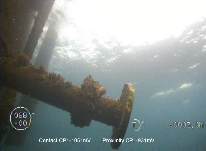
to reinforced polymers or FRP in specific components, such as wind turbine blades. Finally, corrosion prevention depends on a comprehensive plan, which usually includes visual inspections and NDT (ultrasound, eddy current) via ROVs or drones to detect early corrosion; electrochemical monitoring and SHM sensors to check potentials, thicknesses, micro cracks, and microbial activity; and predictive analyses using AI to optimise maintenance times and costs based on environmental and structural data.
Engineering choices regarding materials are also crucial, from duplex or super duplex stainless steels to enhance pitting and stress corrosion resistance to reinforced polymers or FRP in specific components, such as wind turbine blades.
Marine exposure is extremely aggressive: salt spray and UV rays in splash zone areas can cause corrosion thicknesses of up to 500 µm/year, compared with 25-50 µm in C3 onshore environments . There are several critical areas to consider, including the atmospheric zone, which is subject to saline microclimates and intense UV rays; the splash/tidal zone, which is subject to wet/dry cycles and abrasion; and the submerged zone.
In offshore environments, corrosion protection begins with design: the shape of structures, the accessibility of components, and the treatment of welds directly affect the durability of coatings. Details that may seem minor, such as rounded edges, well-finished joints, or access routes, are essential to ensure uniform coverage and prevent the accumulation of water or salt.
Engineering choices regarding materials are also crucial, from duplex or super duplex stainless steels to enhance pitting and stress corrosion resistance
The aim is to combine preventive engineering, advanced and multi-layer coatings, adequate cathodic protection, and continuous monitoring, adopting a life-cycle approach based on the idea that preserving structural integrity reduces downtime and costs while protecting the ecosystem balance and promoting sustainability.
The fight against corrosion in the marine industry cannot, therefore, be reduced to a single system or technology. A combined strategy is needed, from design to predictive maintenance.
This Corrosion Protection issue includes a focus on the marine sector: as mentioned, this is one of the sectors where companies that produce corrosion protection systems concentrate most of their R&D activities, with research aimed at achieving maximum anti-corrosion performance for components. The training of offshore facility operators is equally crucial, to the extent that a course on corrosion has been recently launched for seafarers. Who better than them to keep it under control on a ship?
Enjoy your reading.
NEW WHAT’S
MATCOR’s PF™ Anode achieves NSF-61 certification for safe water system cathodic protection
MATCOR, Inc., a BrandSafway company and a leader in cathodic protection and AC mitigation solutions, proudly announces that its PF™ Anode is now officially NSF/ANSI 61 certified1, ensuring its compliance for potable water applications. This certification validates the PF Anode’s safety for drinking water systems and underscores MATCOR’s commitment to delivering corrosion prevention solutions that meet the industry’s highest standards. The PF™ Anode is designed to prevent corrosion in water tanks, wells, and storage facilities.
Featuring mixed metal oxide (MMO) technology, chlorine-resistant Kynar® braiding, and versatile installation options, it provides longlasting and reliable protection for drinking water infrastructure.
“NSF-61 certification is a significant milestone,” said Ted Huck, Director of Sales at MATCOR. “Customers can trust the PF Anode as a safe, effective, and fully compliant solution for protecting water systems.”
www.matcor.com
Highly effective anti-rust nanocoating for iron developed by Hebrew University of Jerusalem researchers
A dual-layer nanocoating system that significantly improves upon existing rust corrosion prevention methods on iron has been developed by Hebrew University of Jerusalem researchers.
As reported in a study in Angewandte Chemie1, the coating combines a thin molecular primer with a durable polymer layer, creating a strong, long-lasting barrier against rust that provides 99.6% protection against iron corrosion. This innovation could significantly reduce maintenance costs and extend the lifespan of iron-based materials used in construction, transportation, and manufacturing.
Iron is widely used in industries such as construction, transportation, and manufacturing, but it is highly prone to rust when exposed to air and moisture. Rust weakens the metal, leading to structural damage and costly repairs. While protective coatings exist, many tend to degrade over time, offering limited long-term protection.
“This discovery offers a major leap forward in protecting iron from corrosion,” said Prof. Elad Gross of the Hebrew University Institute of Chemistry and the Harvey M. Krueger Family Center for Nanoscience and Nanotechnology.
"By using a specially designed primer, we created a coating that is not only highly effective but also long-lasting. This could reduce maintenance costs, extend the lifespan of iron-based materials, and provide industries with a much more reliable solution.”
The first layer is an ultra-thin coating made of N-Heterocyclic Carbene (NHC) molecules, which form a tight bond with the iron surface. This primer layer ensures that the second layer—a polymer-based coating—sticks firmly, creating a highly stable and durable protective shield. The improved adhesion keeps the coating intact even in harsh conditions, such as prolonged saltwater exposure.
This research was supported by the European Research Council (ERC) under the European Union’s Horizon 2020 research and innovation program (Grant Agreement No. 802769, ERC Starting Grant “MapCat”) and by the Israeli Ministry of Energy (project no. 222–11–090) and the Israeli Ministry of Innovation, Science and Technology (project no. 1001817851). L. A. acknowledges the Harvey M. Krueger Family Center for Nanoscience and Nanotechnology for their financial support.
http://new.huji.ac.il/en and www.afhu.org
Xodus unveils jobs guide for Australia’s Marinus Link project
Marinus Link is a proposed undersea and underground electricity and data interconnector that will connect North West Tasmania with Victoria, enabling the flow of more low-cost renewable energy in both directions.
Construction on the project, which is currently in the design and approvals phase, is scheduled to get underway in 2026 and is anticipated to create up to 3,300 direct and indirect jobs. According to research from Ernst and Young (EY), Marinus Link is also expected to deliver approximately $3.9 billion in economic stimulus for Tasmania and Victoria.
Xodus was tasked by Marinus Link with mapping the construction and operations workforce opportunities, to improve understanding of how the project would develop and promote local content. The resulting guide outlines the anticipated workforce needs, broken down by sector, and discipline area.
By providing indicative position descriptions for each anticipated onshore and offshore role - including qualifications and training requirements - the manual will be an invaluable tool, providing examples of local training and education pathways for local residents, and the wider Australian community, to work on the project.
Lara Taylor, Lead Renewables Consultant, Xodus, said: “This guide builds on Xodus’ extensive experience with workforce development strategies for complex energy projects, which includes offshore wind, hydrogen and subsea interconnectors, providing tangible examples of the typical roles that will be available to the local workforce.
“It also highlights opportunities for specialist roles, including those in offshore vessels, onshore transmission, and horizontal directional drilling (HDD). By outlining workforce requirements at this early stage, the easily accessible guide will assist both Marinus Link and its subcontractors in planning for the project’s needs.
“Marinus Link is a crucial project for Australia’s East Coast, a region that has faced significant electricity shortages, threats of blackouts, and price hikes in recent years. By unlocking worldclass renewable resources and enabling the flow of power it will shore up the region’s energy supply, delivering benefits to businesses and consumers alike.”
Once complete, Marinus Link will mean that Tasmania can import low-cost renewable power, such as surplus solar, while reserving hydropower and storing the extra energy. Green hydropower can then be exported to the mainland grid as and when its needed, with Tasmania acting as a large battery for the nation, thereby enhancing grid stability and lowering electricity prices.
The jobs guide offers a representative and non-exhaustive overview of the roles likely to be available on the development, which can be used by universities and schools. It also gives an overview of where the positions will be located and what project phase they will be working in, listing the relevant training providers in both Tasmania and Victoria, as well as in wider Australia.
Marinus Link is jointly owned by the Federal government (49%), Tasmanian state government (17.7%) and Victorian (33.3%) state government.
www.xodusgroup.com
Hempel launches Hempaguard NB, the first silicone hull coating for newbuilds
Hempel expands its market-leading Hempaguard range with the launch of Hempaguard NB - a breakthrough high-performance silicone hull coating, designed specifically for newbuild vessels. For the first time, shipowners and shipyards can access Hempaguard’s trusted fuel savings and fouling protection during the construction phase, marking a major step forward in hull coating innovation. Until now, applying advanced silicone coatings during the newbuilding process has posed logistical challenges for shipowners. Conventional silicone solutions require controlled environments and are typically applied either pre-delivery or in post-delivery dry dockings, both of which cause delays and additional costs.
“Hempaguard NB brings the industry’s most advanced silicone hull coating technology, proven to deliver significant fuel savings and reduce emissions, into the newbuilding phase for the very first time,” says Alexander Enström, Executive Vice President and Head of Marine at Hempel A/S. “Developing Hempaguard NB meant reimagining how silicone coatings are formulated for the construction phase, delivering a solution that maintains long-term performance without the need for post-delivery application. It’s a technical breakthrough that ensures vessels are equipped with proven, highefficiency fouling protection from the very first day at sea.”
It combines the tried-and-tested performance of Hempaguard X7 with a revolutionary new silicone topcoat, made specifically for newbuilds. This means that it offers the same exceptional performance as Hempaguard X7 - with nearly 5,000 applications and independently verified for its fuel-saving and decarbonisation benefits1. Shipowners can expect up to 20% fuel savings, only 1.2% average speed loss2 and 120 fouling-free idle days.
Not only does this give customers premium performance straight out of dock, but also a long-term asset for operational efficiency and regulatory compliance, unlocking the full potential of silicone coatings for newbuilds and giving shipyards a competitive edge. Hempaguard NB plays a part in Hempel’s Full Picture Hull Management approach – a comprehensive, data-driven perspective to hull performance, shaped by more than a century of experience and close collaboration with the maritime industry.
www.hempel.com/markets/marine
1 In 2024, DNV verified that Hempaguard X7 reduces fuel consumption by 19% and speed loss by 1.4%. Since then, additional performance data has become available, supporting a further reduction in the reported speed loss percentage.
2 Speed loss measurements are used to monitor how much a ship’s speed has decreased compared to its optimal or expected speed.
Montipower Americas Inc. acquires majority stake in Great Lakes Gages LLC
Montipower Americas Inc. has acquired a majority stake in Great Lakes Gages LLC (“GLG”), a leading supplier of industrial and coating inspection equipment based in Metamora, Michigan, USA. Founded and lead by Joel Bialek, GLG distributes and services some of the industry’s leading brands including TQC Sheen, Defelsko, RAL and Coatmaster from Switzerland, among many others.
“Monti is excited to be able to partner with Joel and GLG in the growing market for industrial and coating inspection tools” – said J. F. Doddema, MONTI Group CEO. “We have known Joel for many years as GLG also distributes MONTI tools and accessories and it frequently cooperates with MONTI’s subsidiary M-Testco in Houston for tool support and tool certifications. GLG and M-Testco service similar markets and share many synergies in terms of their products and services”.
MONTI’s Testco’s Inc. headquarters is in Houston. Their customers often work with the users of Monti tools and are in
positions to influence the purchase of Monti tools. They specialise in different, but related, areas: M-Testco in liquid coatings and field focused, while GLG is in powder coatings and more plant focused. We expect to drive growth of the two companies through building these synergies and cross-selling.
“M-Testco’s satellite offices in Louisiana, Odessa (Permian Basin) and Corpus Christi (Marina and Offshore) will aid these efforts by bringing us closer to important markets on the gulf coast. We look forward to having GLG and M-Testco work more closely together in the coming years to build their respective businesses in these interesting growth markets, while simultaneously supporting MontiPower’s efforts to expand its presence and reach in North America,” concludes Doddema.
www.montipower.com and www.greatlakesgages.com
Resicoat powder coating provides corrosion protection for potable water infrastructure for up to 25 years
AkzoNobel’s Resicoat powder coating has successfully completed a 25-year real-world study in Germany, independently confirming its long-term corrosion protection for potable water infrastructure.
A Resicoat powder coating from AkzoNobel has become one of the first products of its kind to complete a 25-year real-world study to prove its ability to protect valves and fittings as the infrastructure of potable water from the damaging effects of corrosion. The study, conducted in Bad Bentheim, Germany, by an industry association and a water board and verified by the MPA Hannover testing institute, has independently confirmed that Resicoat epoxy powder coating provides durable, long-term anticorrosion protection for drinking water supply systems.
The results demonstrate a new standard in protecting potable water networks and give water infrastructure companies and their customers even greater confidence in the efficacy of their supply infrastructure.
Water systems often fail due to corrosion of pipes and other metal components, such as valves and fittings. Anti corrosion protection is essential to prevent physical failures that can lead to leaking, burst pipes, flooding and unsafe water supplies.
A fully operational test valves and fittings installed in a drinking water pipe had epoxy powder coatings applied before being buried two meters underground, the standard depth for water pipes worldwide.
When the pipeline was unearthed, it showed no leaks and water flowed freely and Resicoat’s epoxy coatings displayed no delamination or cracking. With no impacting signs of corrosion, the results showed the integrity of the pipeline had been preserved.
Yidong Meng, Global Functional Segment Manager at AkzoNobel Powder Coatings, says the tests prove how epoxy powder coatings can deliver the long-term corrosion protection needed to extend the service life of water systems: “In doing so, these solutions make water supply systems more reliable, and help reduce maintenance costs,” he says. “Epoxy powder coatings are more dependable than ‘traditional’ paint or enamel coatings and consequently help minimize water wastage due to leaks and floods. Ultimately, this ensures a reliable, sustainable source of clean drinking water for millions of people around the world.”
Resicoat R series is high quality thermosetting epoxy powder coating specifically designed for the coating protection of cast iron or steel valves and fittings used in water and gas distribution networks. The powder coating is applied in one layer on a preheated surface by fluidised bed or electrostatic spray application.
Lars Walther, General Manager of GSK, says that the results prove epoxy powder coatings are the best answer to tackling corrosion: “This comprehensive study provides the market with important, independent, and irrefutable proof of the value of epoxy powder coatings in safeguarding the integrity of potable water supplies. It will give even greater confidence to water suppliers that one of the most challenging of all challenging issues to their pipes and associated infrastructure has a credible, long-term solution.” The Bad Bentheim long-term test involved more than 10 companies and was jointly run by the GSK (Quality Association Heavy-Duty Corrosion Protection of Valves and Fittings with Powder Coating e.V.) and the Wasserbeschaffungsverband Obergrafschaft Bad Bentheim (Water Supply Association of Upper County Bad Bentheim and Surrounding Areas).
www.interpon.com
Consulting for the professional and productive world.
Germedia addresses both the professional and productive sectors. Thanks to its cross-disciplinary expertise, it collaborates not only with professionals such as architects, engineers, and law firms, but also with builders, paint manufacturers, and craftsmen.
Steelpaint’s Stelcatec steel protection approved for UK rail infrastructure
A newly certified protective coating system from German manufacturer Steelpaint GmbH is gaining attention across the UK rail sector following successful demonstration and approval by Network Rail.
The company’s Stelcatec three-layer moisture-cured urethane coating, distributed by Recoat UK, is now formally listed under Network Rail’s specification XM92/M24 and offers rail contractors a faster, simpler, and more flexible approach to corrosion protection and steel maintenance.
Approved in January 2025, Stelcatec is engineered for in-field applications, allowing for full protection of steelwork without the logistical burden of multi-component coatings or other corrosion prevention solutions.
In a demonstration held in March at Specialist Painting Group’s facility in Peterborough, Stelcatec was applied to three “gingered” steel samples manually cleaned to St3 standard, under realistic ambient conditions of 13°C. The full three-coat system was applied within four hours using only rollers. Pull-off adhesion testing later confirmed the system’s performance on marginally prepared substrates.
“This isn’t about just meeting the spec,” said Andreas Engert, Technical Director at Steelpaint. “This is about optimising steel protection, application process and cost efficiencies. Stelcatec was formulated with all of these requirements in mind. Applicators were surprised at how easily they could finish a job in one shift, not three.”
The event was attended by representatives from Network Rail and several leading painting contractors and consultants. Their participation not only validated the product’s technical capability but demonstrated industry appetite for alternatives to traditional multi-pack systems, which often require site-specific mixing, tight environmental controls, and extended drying times.
Steelpaint Director Frank Müller pointed out that the system represents a broader change in approach. “Rail infrastructure development and maintenance must be more agile. What we are providing Network Rail is a product that can be used by small teams, under real-world conditions, with minimal disruption to rail operations.”
Recoat UK, which has worked closely with Steelpaint over the past two years to introduce the product to the British market, sees the certification as a commercial turning point.
“It’s a rare opportunity when something comes along that saves time, reduces risk, and performs to the highest standards,” said Perry Poppelaars, Director at Recoat. “Stelcatec ticks all those boxes.”
Unlike traditional epoxy coating systems, Stelcatec does not require complicated mixing or the use of hazardous hardeners. As a onecomponent moisture-curing polyurethane, it is applied directly from the can, cures rapidly even in high humidity, and provides strong adhesion on manually prepared steel – a crucial feature when blast cleaning is not practical.
The demonstration day was organised to coincide with the system’s approval and to show applicators and specifiers exactly what the product can achieve. All coatings were applied using standard rollers, with no special equipment or ventilation, and no delays due to weather. Application times were kept to a minimum, with recoat intervals measured in hours rather than days.
Since the event, several contractors have expressed interest in trialing Stelcatec on Network Rail infrastructure. Recoat has begun providing support and training to contractors seeking to adopt the system into their maintenance workflows. While initial focus is on small to mid-sized bridge and platform assets, larger-scale applications are expected to follow once the system is proven in service. Recoat has already signed a contract to apply Stelcatec to the bridge at Roding Valley station, which is maintained by Transport for London.
The move aligns with broader shifts in infrastructure management where coatings are selected not only for their technical durability but for their operational efficiency. Projects requiring fewer operatives, less kit, and shorter closure periods are increasingly favoured as network managers balance safety, cost, and continuity of service. Engert said the company is already looking to expand the system’s use across other regulated sectors. “Wherever there is a need for tough, easy-to-apply corrosion protection this technology fits.”
The Stelcatec approval places Steelpaint alongside a small group of specialist manufacturers whose products meet Network Rail’s performance and safety standards. With its UK operations now underway and feedback from its demonstration highly positive, the company is poised to make significant inroads in Britain’s £1.3 billion annual rail maintenance market.
www.steelpaint.de/en/
AkzoNobel marine coatings protecting world’s first sail-assisted Aframax tanker
The world’s first Aframax oil tanker to use wind-assisted propulsion has been built in China, with AkzoNobel making an important contribution to the landmark project by supplying 350,000 litres of International® marine coatings. The Brands Hatch is regarded as a major innovation in sustainable shipping technology and the entire vessel – including the underwater hull, deck and cargo oil tanks – features the company’s high-performance products. They’ll provide comprehensive protection and critical technical assurance for the tanker’s eco-efficient operation.
Built by Shanghai Waigaoqiao Shipbuilding Co., Ltd., it has three intelligent fiberglass sails which are projected to reduce fuel consumption by around 12% a year and slash annual carbon emissions by 5,000 tons under normal operating conditions.
“We’re very proud to have contributed to this landmark project,” says Rob Leslie, Commercial Director of Marine and Protective Coatings for AkzoNobel Greater China. “The successful application of our coatings not only validates the performance of our International fouling control and anti-corrosive technologies, but also demonstrates the company’s commitment to enabling decarbonization through sustainable innovation.”
The products used included Intercept® 8500 LPP – one of the highest-performing fouling control technologies in the International range – which was applied to the vessel’s underwater hull. This advanced coating delivers consistent and effective performance for a clean, foul-free hull. By combining linear polishing technology with an optimized biocide package, the coating contributes to significant fuel savings and reduced CO₂ emissions.
Built for UK shipping company Union Maritime, the Brands Hatch is an Aframax ship, a type of oil tanker with a capacity between 80,000 and 120,000 deadweight tons. They are primarily used for short to medium-haul crude oil transportation.
It’s the third milestone vessel built in China to be coated by AkzoNobel in recent years. The company also supplied more than 300,000 litres of International marine coatings for Dream – the country’s first domestically designed and built ultra deep-sea drilling vessel – while Intersmooth® fouling control technology was used on Adora Magic City, the first large cruise ship to be constructed in China.
www.akzonobel.com
There are over 10,000 Level I, II and III inspectors in 74 countries worldwide, as large clients consider the qualification of Coating Inspector Frosio as a reference for monitoring the quality of the application of a painting cycle.
There are 367 active Certifications in Italy, of which 109 Level I (white card), 115 Level II (Green card) and 143 Level III (red card). The certification is in accordance with the Frosio Certification SCHEME, which follows the requirements of ISO 17024.
The University of Genova, accredited by FROSIO as a Training Body, is in charge of organising courses in the Italian language exclusively for the Italian territory. To date, 20 courses have been organised.
The Gruppo IspAC Associazione (GIA), accredited by FROSIO as Certifying Body, is in charge of organising the exams for the Qualification and Certification of Coating Inspectors Level I, II and III, renewal of certifications and level ups exclusively for the Italian territory.
THINKING BIG RIGHT FROM THE SMALLEST THINGS: DONELLI ALEXO’S FBE AND TSA COATINGS FOR CRITICAL ASSETS IN HIGHLY CORROSIVE ENVIRONMENTS
MONICA FUMAGALLI, ipcm®
Donelli Alexo has developed advanced expertise in the application of FBE and TSA coatings, establishing itself as a strategic partner for the industrial valve field, particularly in the oil & gas and drinking water sectors. A flexible production facility, cutting-edge technologies, and a specialised team guarantee quality, regulatory compliance, and an increasingly sustainability-oriented approach, as also demonstrated by the company’s recent ESG journey.
According to data reported by Prometeia, a company specialising in consulting, software development, and economic research for banks, insurance companies, and businesses, 140 of the approximately 800 companies operating in the Italian valve industry are involved in the oil & gas sector. Italy holds a leading position in Europe, with a 40% share of the continent’s production of valves for the oil sector, with the Lombardy region serving as the main production hub1
Donelli Alexo, a part of the long-standing Donelli Group, has developed specific processes for applying increasingly high-performance FBE and TSA coatings, supporting numerous industrial valve manufacturers in the development of advanced protection solutions.
In this field, mechanical performance and surface treatments for corrosion resistance are critical to the quality and durability of the finished products. And it is precisely on these aspects that Donelli Alexo, a company of the Donelli Group, has been focusing. A long-standing Italian company in the corrosion protection sector, its services include industrial painting, anti-corrosion and anti-acid coatings, metallising, waterproofing, passive protection against hydrocarbon and cellulosic fires, and insulation. Recently, it has also developed increasingly high-performance processes for FBE and TSA applications, thus supporting numerous industrial valve manufacturers in the development of advanced protection solutions.
“By working closely with valve manufacturers,” emphasises Alessio Trisolino, CEO of Donelli Alexo, “we have helped bring to market solutions that were not widely used until recently, such as the application of FBE (Fusion Bonded Epoxy) solutions2, which we have quickly demonstrated to be effective in terms of durability and protective performance. At the same time, we have developed optimised management of TSA (Thermal Spray Aluminium) coating cycles, ensuring high quality standards and full compliance with oil & gas and drinking water specifications. All this is also part of Donelli’s commitment to sustainability, as demonstrated by our first energy balance sheet, which marked a milestone in our ESG journey.”
Thanks to a production structure spread across five interconnected sites, three of which are located within a radius of about 20 km (the Cuggiono, Cuggiono CX, and Ferno MPX plants3), and the creation of a highly specialised work team, Donelli Alexo has soon become a benchmark FBE and TSA applicator. “We have put together a team of four individuals with widely recognised skills, who work flexibly across the three plants to optimise application operations and resource management, thanks to their ability to quickly understand technical and infrastructural requirements and tackle them accordingly,” explains Trisolino. “This group consists of Alessandro Vanacore, Operations Manager; Marco Malandra, Technical and Quality
Coordinator; Luca Calore, NACE Coating Level 3 Inspector; and me, in charge of technical and process-related aspects.”
Donelli Alexo’s strategy: ensuring production continuity through a flexible structure
With the tightening of technical requirements for corrosion protection and valve sealing, especially in the petrochemical and water sectors, several Italian manufacturers have found it challenging to respond competitively to the specifications imposed by large international customers, such as Aramco’s requirements for the oil & gas and drinking water sectors.
“A few years ago, we identified a critical issue in the market: many Italian valve manufacturers were struggling to find coating solutions that complied with these specifications, often resorting to cladding, a process that is significantly more expensive than FBE,” Trisolino points out. “That led to the loss of significant orders. Therefore, about five years ago, we reorganised our production structure with the aim of ensuring operational continuity even for large orders by optimising the application of complex coatings such as FBE ones within a short time.”
The resulting working model, based on a wellstructured production network managed by a dynamic technical team, has enabled Donelli Alexo to provide its customers with a single point of reference while efficiently coordinating over 120 employees. This approach has contributed to the widespread adoption and success of FBE coatings for valves in critical applications. “Among our most significant projects,” says Trisolino with satisfaction, “is the recent collaboration with ORION Spa (Trieste, Italy), which publicly thanked us for the application of the 3M Scotchkote XC 6171 Fusion Bonded Epoxy coating on 1,400 valves in just four months as part of the Zuluf project – one of the major offshore developments promoted by Saudi Aramco – in full compliance with the APCS 102B specifications for service in seawater up to 95 °C. As ORION itself stated, it initially seemed an almost impossible challenge, and it would have been difficult to achieve the same results without a coordinated organisational structure such as ours.”
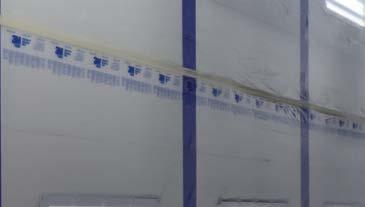
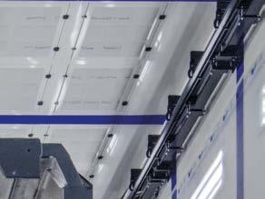
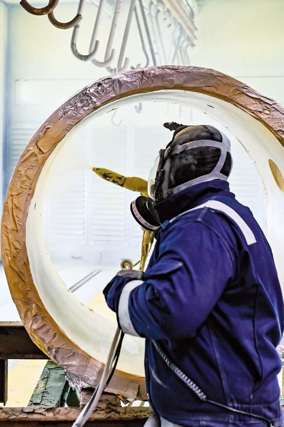
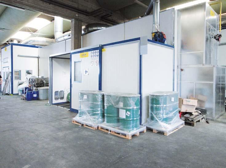
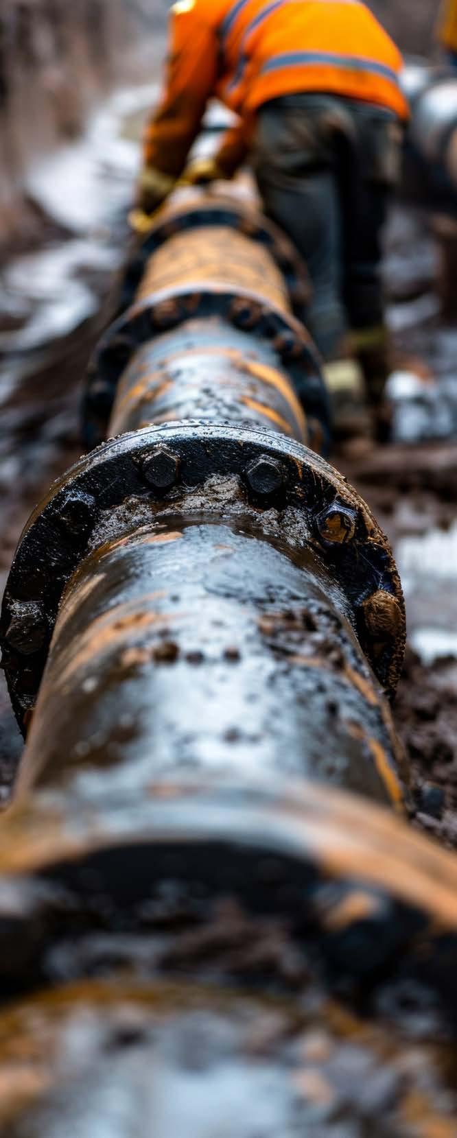
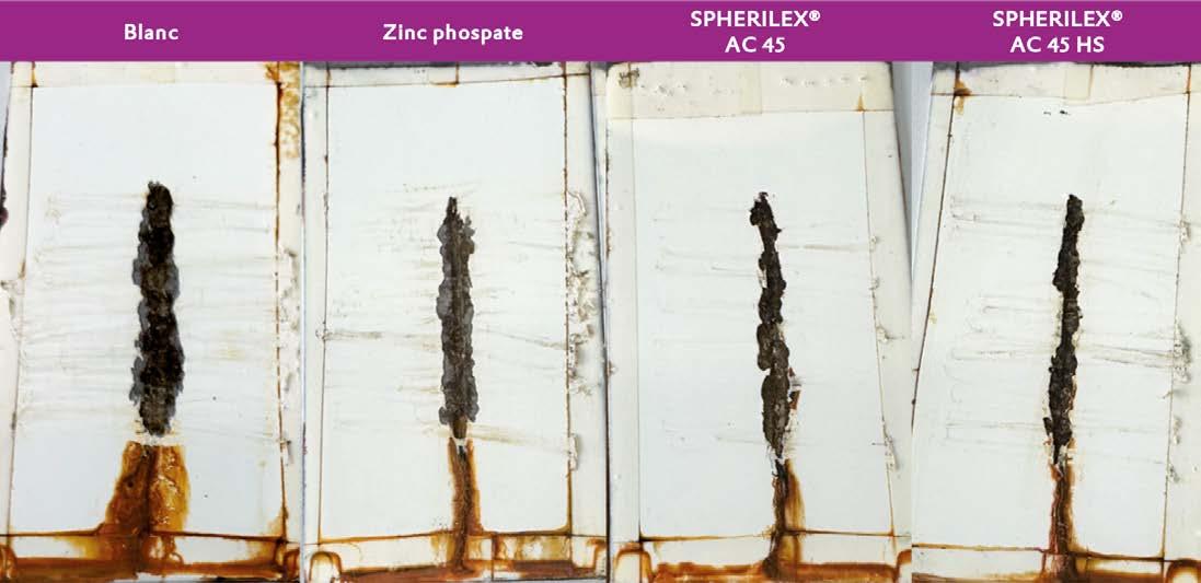
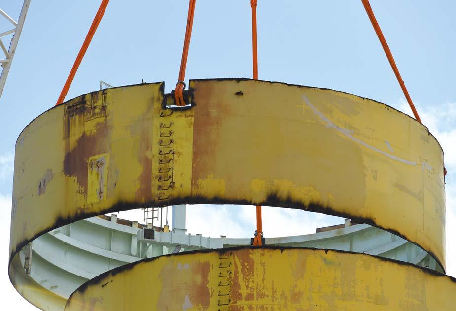
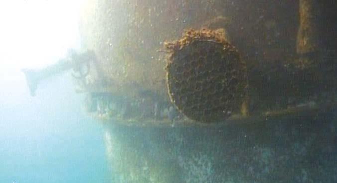
From top left, clockwise:
- The MPX plant in Ferno (Varese, Italy) houses two shot blasting machines and five coating booths.
- One of the two shot blasting machines at the Ferno plant.
- A TSA coating process requires melting aluminium at 600 °C.
- Applying an FBE coating.
RECENTLY, DONELLI ALEXO
The standard FBE coating process
FBE coatings are thermosetting powder-based systems that melt and cure on contact with the metal surface. The process involves electrostatic spraying of epoxy powder onto a primed and preheated surface, where it melts, spreads evenly, and then it is cured in the oven to form a durable, corrosion-resistant protective layer. “This type of coating product,” says Alessandro Vanacore, Operations Manager and a member of the highly specialised technical team, “stands out for its excellent corrosion resistance even in very aggressive environments, good tolerance to impact and bending, and long-lasting adhesion to the substrate. One of the most significant aspects of FBE is its impermeability even in areas subject to machining, such as sealing seats, where the continuity of the coating is crucial for protecting the exposed metal. Precisely because of these characteristics, FBE is particularly suitable for protecting components such as valves, pipes, and fittings used to transport hydrocarbons, drinking water, and industrial fluids.”
The FBE application process requires strict control of thermal and environmental parameters (e.g. surface pre-treatment, compressed air, substrate temperature, and polymerisation conditions) to ensure uniformity, thicknesses, and performance in line with international specifications. Upon receiving a valve, a preliminary inspection is conducted to assess its degree of mechanical surface preparation, which is crucial for the effectiveness of the applied lining. “The P3 grade as per ISO 8501 is mandatory to ensure the durability of the treatment on steel surfaces,” explains Trisolino. “This check is carried out by our inhouse quality specialists, who are certified inspectors.”
The first process stage is degreasing, which is performed in a saturated steam machine at 170 °C or a laser cleaning station, removing any oil residues and contaminants from the surfaces. This is followed by shot blasting and the application of a waterbased primer. The valve is then preheated in an oven at a temperature of 177 to 202 °C, after which the thermosetting
powder is applied until the specified thickness is reached; the compressed air used must have a dew point below -20 °C (but can reach up to -40 °C) to ensure the absence of moisture. The final stage is curing in an oven at temperatures between 200 and 242 °C for approximately 30 minutes. The entire process is continuously monitored by last-generation probes connected to the oven’s PLC. At the end, some samples are selected and sent to an external laboratory, which issues a report confirming compliance with the parameters specified in the customer’s technical specifications. “Every day, several inspectors check the correctness of our processes, including ‘resident’ inspectors, i.e. technical staff appointed directly by the end customers to continuously monitor and verify our QC activities in all the three factories – this is another advantage of having our production sites close to each other,” notes Trisolino.
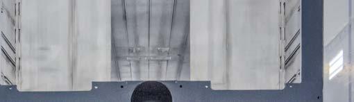
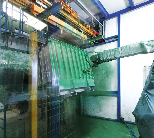
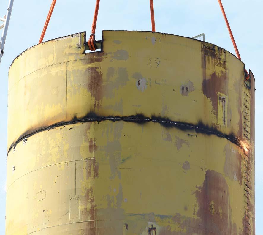
From left to right:
TSA is particularly effective against galvanic corrosion and corrosion under insulation (CUI).
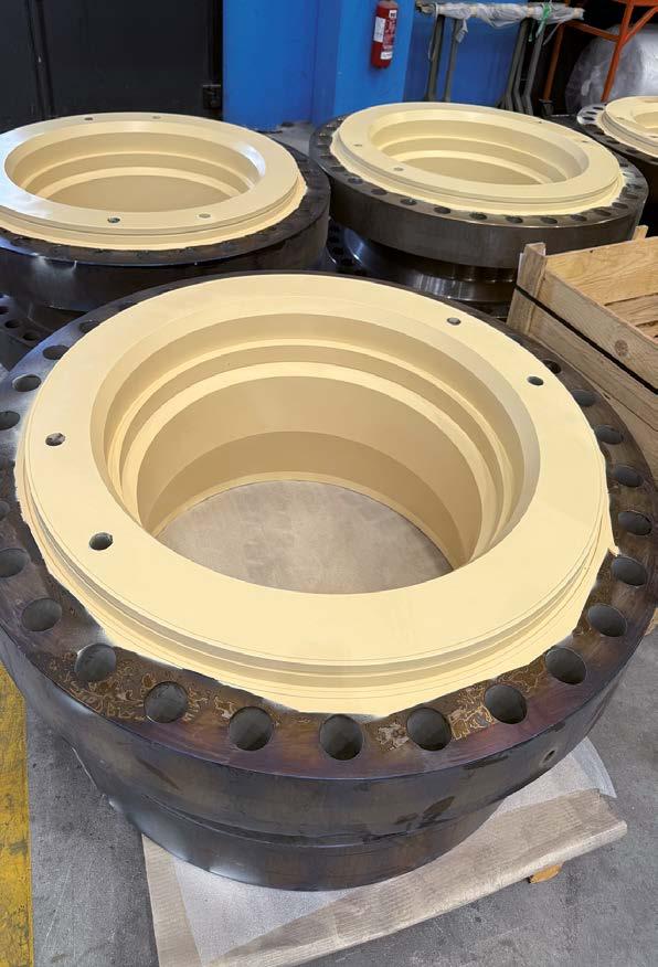
Attention to detail allows the Donelli Alexo team to achieve perfect finishes in accordance with regulations.
One of the other operations carried out at the Ferno plant, which has recently obtained Qualisteelcoat certification.
Donelli Group boasts over a century of expertise in protective coatings for equipment, plants, and structures in the energy, Oil & Gas, and food industries, delivered with full compliance to environmental, quality, and safety standard.
Some valves coated with FBE: one of the most important aspects is its impermeability even in areas subject to machining.
A TSA coating process for a major food processing plant
“TSA, on the other hand, is a coating technology based on a thermal spray, or metallising, process,” says Vanacore, “in which aluminium is melted at 600 °C and sprayed onto the substrate at high speed. This operation, which uses high-purity aluminium, produces a coating characterised by high adhesion properties and a lamellar structure. The result is a durable metal barrier that is particularly effective against galvanic corrosion and corrosion under insulation (CUI), even in high-salinity environments or marine atmospheres. Unlike organic coatings, TSA also provides active cathodic protection, combining the barrier effect of metal with high resistance to moisture penetration. Moreover, it is compatible with the application of a top coat, both to increase UV protection and for aesthetic purposes, and is widely used in contexts such as offshore installations, refineries, LNG terminals, and infrastructure subject to extreme temperature fluctuations.”
One of the most recent projects in which the Donelli Alexo team has been able to put all its know-how to good use was for Europe’s largest whisky distillation plant, to be installed in Scotland. “In this case,” illustrates Vanacore, “the cycle included the application of a TSA coating to protect 304 stainless steel against corrosion under insulation, followed by the installation of a double layer of FOAMGLAS® cellular glass and the application of an external AISI 316 coating to ensure thermal insulation. This was a food processing plant, but with characteristics comparable to those of a refinery in terms of size, volumes, and footprint.”
“That is what the market demands today: the most important food engineering companies are imposing specifications very similar to those of the petrochemical sector,” adds Trisolino, “because the continuous alternation between high temperatures and
production stoppages can trigger localised corrosion, particularly on welds under insulation. In CX systems as per ISO 12944, this is the top-of-the-range solution, as also demonstrated by another significant project, currently at an advanced stage of preparation and scheduled for August: the on-site application of a TSA coating on an offshore structure to upgrade it and double its productivity.”
These projects demonstrate not only Donelli Alexo’s high level of technical expertise but also its ability to respond promptly to the needs of highly regulated and constantly evolving industries. At the same time, such a focus on innovation has also given rise to a broader commitment to environmental and social sustainability.
Donelli Alexo and its first sustainability report
The company’s ESG journey began by following the example of its customers and suppliers: “We started with a reactive approach, but over time, we felt the need to take a more structured approach inspired by the ESG models adopted by some of our business partners. This led to the realisation that we needed a proactive strategy on sustainability issues. To develop
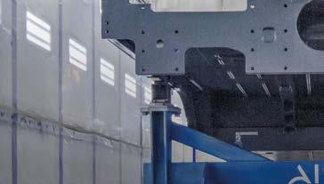
From left to right:
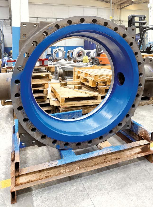
A finished valve ready to be sent to the customer.
one, we set up an internal ESG committee and involved external partners to start calculating our carbon footprint from 2023, as a first step towards reducing emissions. We then defined a strategic sustainability plan and began drafting our 2024 Sustainability Report, which we completed recently. This document identifies five fundamental pillars – process, planet, partners, people, and principles – as the priority areas for acting in line with our integrated approach to sustainability. One of the key elements of this strategy is energy efficiency, pursued through investments in new plants where automation and advanced monitoring systems play a central role, as well as through the re-evaluation of operating practices and habits that are no longer optimal. “Thanks to our desire to innovate a complex industry, our attention to the needs of a highly regulated and constantly evolving market, our transparency in the management of orders, and last but not least, the know-how of the team we have built, we can now state that Donelli Alexo has contributed to developing and establishing technologies that were previously little known. Because we are used to thinking big… right from the smallest things,” concludes Trisolino. ‹
"THANKS TO OUR DESIRE TO INNOVATE A COMPLEX INDUSTRY, OUR ATTENTION TO THE NEEDS OF A HIGHLY REGULATED AND CONSTANTLY EVOLVING MARKET, OUR TRANSPARENCY IN THE MANAGEMENT OF ORDERS, AND LAST BUT NOT LEAST, THE KNOW-HOW OF THE TEAM WE HAVE BUILT, WE CAN NOW STATE THAT DONELLI ALEXO HAS CONTRIBUTED TO DEVELOPING AND ESTABLISHING TECHNOLOGIES THAT WERE PREVIOUSLY LITTLE KNOWN."
ADVANCEMENTS
Make lube point a touch point for corrosion protection
Edited by Cortec® Advertising Agency
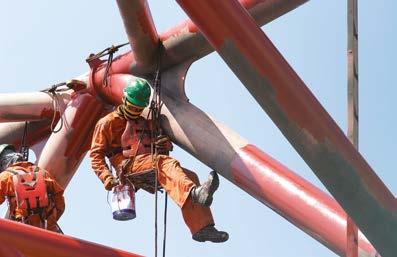
Grease “makes the world go round.” Corrosion grinds it to a halt. Fortunately for most lube applications, the very presence of grease is enough to hinder corrosion on bearings, bushings, and other metal-tometal contact areas. However, some conditions such as offshore platforms and facilities undergoing layup face a higher risk of corrosion. For vulnerable applications such as these, Cortec® Corporation recommends two greases with enhanced corrosion protection.
NLGI Grade 2 + Corrosion Protection
CorrLube™ VpCI® Lithium EP Grease is a lithium complex grease with low speed / high pressure resistance and superior corrosion inhibiting properties against salt water, brine, H2S, and other corrosive agents. These characteristics are particularly important for equipment layup on offshore platforms or in almost any industrial environment. When equipment is idle for long periods of time, it is easy for grease to go bad and for moisture or other corrosives from the air to creep in. The risk is even higher in marine environments with high humidity, salt spray, and chlorides in the air.
With CorrLube™, asset owners can protect their lube points against corrosion while providing the necessary lubrication. An added benefit is that workers do not need to remove one grease and replace it with another when switching from operation to layup and back again.
This is especially helpful for equipment that operates intermittently. CorrLube™ VpCI® Lithium EP Grease is NLGI Grade 2, which makes it applicable to most common lube applications for bearings, bushings, and lubricating sleeves.
NLGI Grade 3 + Corrosion Protection + Biobased
Some applications have higher speeds that require a thicker, more stable NLGI Grade 3 grease. When this is the case, EcoLine® Biobased Grease is a great option. This grease not only exhibits high pressure properties but also contains Vapour phase Corrosion Inhibitors that protect metals in direct contact with the grease as well as those in surrounding enclosed cavities, making it ideal for layup when protection is needed most. A high dropping point also facilitates use in a broad range of operating temperatures. A further benefit in an ecological sense is that EcoLine® Biobased Grease is a USDA Certified Biobased Product that contains 86% USDA certified biobased content, allowing users to launch a sustainability initiative while protecting their assets.
Give lube points a boost of protection
Bearings, bushings, and high friction areas always need grease, but the option of simultaneously including extra corrosion protection is an added benefit. By preventing corrosion, maintenance can encourage the longevity of the components and reduce downtime and other complications from rust. ‹
Grease is essential for reducing friction, but it can also serve as a first line of defence against corrosion. Cortec® offers advanced greases with enhanced corrosion-inhibiting properties in harsh environments or during equipment layup.
When the paint supplier’s technical support
is
key to
the
high performance of protective coatings for electrical transformers
Monica Fumagalli, ipcm®
How much can technical advice from a partner with in-depth coating expertise influence paint performance? At Newton Trasformatori, the specialist support offered by Sherwin-Williams, the long-standing supplier of coatings to this Tuscany-based manufacturer of transformers for electrical power management, has proved strategic in optimising coating cycles and achieving the high degree of corrosion protection performance required for its devices intended for C4 and C5-M environments.
Atransformer is a static electrical device that operates on alternating current, based on the principle of electromagnetic induction. Its purpose is to transfer electrical power between two separate circuits through inductive coupling, modifying voltage and current but keeping the frequency constant. This ability to transform electrical energy makes the transformer a crucial component in any power generation, transmission, and distribution system. Despite sharing the same operating principle, these devices come in a wide variety of sizes, from tiny signal transformers used in electronic and audio equipment to massive units weighing hundreds of tonnes, used in substations to interconnect portions of national grids or power large industrial plants. Although the introduction of new technologies has led to a reduced use of traditional transformers in specific sectors, these devices remain vital for alternating current management, particularly in long-distance transmission, which requires high voltages. At the same time, with the ever-increasing demands related to the energy transition and widespread electrification, amplified by the requirements of rail traction, data centres, electric vehicles, and renewable energies, there is a growing need for direct current solutions, with more compact high-frequency transformers integrated into advanced power systems.
Newton Trasformatori Spa (Poggibonsi, Siena, Italy) has been specialising in the design and manufacture of distribution and power transformers for complex applications, even in extreme conditions, for over forty years. “Our company has developed hand in hand with the evolution and expansion of the national and international electricity grid,” says Lorenzo Zoncada, Process and Plant Engineering Manager at Newton, “so much so that today our customers include leading companies such as Sonepar, ABB, Enel, Enel Romania, Endesa, Ferrovie dello Stato Italiane, ENISaipem, RFI, Jepco (Jordan), and Hitech (Russia), to name but a few.”
This Tuscan company designs transformers for completely exposed structures that are subject to thermal shocks, aggressive atmospheric agents, pollutants, and salt and for which surface protection plays a strategic role. To guarantee the durability of their components, it uses ISO 12944-compliant, class C4 and C5-M protective coatings that ensure outstanding performance even in highly corrosive environments. To this end, it has always relied on Sherwin-Williams water-based paint products.
“Until a few years ago, for the surface coating of the casings and other components of our transformers, we only used a dip coating plant supplemented by a manual application booth.
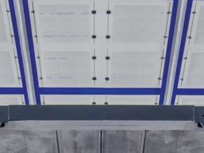
From top: To ensure the durability of its components, Newton Trasformatori Spa uses class C4 and C5-M protective coatings in compliance with ISO 12944; A casing inside the OMSG shot blasting machine; The Savim Europe coating plant is equipped with a CM Automazione power & free conveyor with 92 load bars, each with a maximum load capacity of 500 kg.
However, due to increasing demands and growing production volumes, we decided to upgrade our coating department by adding a new line that integrates the most innovative systems and devices available on the market: a plant from Savim Europe (Arbizzano, Verona, Italy), a conveyor from CM Automazione (Giussano, Monza e Brianza, Italy), two booths with articulated robots from Lesta (Dairago, Milan, Italy), and a paint management unit and application equipment from Wagner. We also reviewed and updated our entire coating process in partnership with the Sherwin-Williams team in Tuscany and Protek, a distributor of Wagner devices, to optimise our application cycle and achieve higher uniformity, greater paint adhesion, and overall better results.”
Newton’s transformers ensure reliability through robust design and resilience to extreme conditions like Arctic cold (down to -60 °C) and desert sandstorms, meeting high standards in surface treatment and corrosion protection.
Power management with Newton’s transformers
To understand the strategic role of transformers in managing the electrical grid, an overview of the energy distribution structure itself can be helpful. “Electricity,” explains Zoncada, “is transmitted over long distances at high voltage to minimise energy losses. In Italy, for example, high-voltage lines operate at very high values. At the entrance to built-up areas, the voltage undergoes an initial transformation through large power transformers, which generally reduce it to 15,000 to 20,000 volts (medium voltage).
This energy, which is not yet directly usable by consumers, is then distributed within the urban and industrial areas, where a second set of equipment comes into play: distribution transformers. These devices carry out the final stage of the process, reducing the voltage to 220 or 400 volts, i.e. values compatible with domestic and commercial use.”
Newton Trasformatori’s entry into the mega transformer sector is the most recent and advanced milestone in an industrial journey that began over forty years ago. This segment, which is constantly growing, now accounts for approximately 5% of the company’s total production. Distribution transformers, a sector in which Newton has gained extensive experience and consolidated its market position, still account for the remaining 95%.
“This firm was founded in 1982 in a factory of just over 500 m². Thanks to the work of its highly specialised team led by our current president Guglielmo Montagnani, its professionalism,
flexibility, and customer focus as well as the use of advanced design methods and dedication to meeting commitments, Newton quickly grew from a small artisan business to a major industrial enterprise covering 20,000 m², up to becoming a key player in the national and international markets.” While remaining a family-run company, Newton has recently begun a transition process between the second and third generations, with the latter still too young to join the company, by relying on a management team composed of Stefano Moretti (CEO) and Samuele Paiusco (COO) and adopting a matrix-type organisational structure.
The build quality of Newton’s transformers
Newton designs and manufactures high-efficiency transformers aimed at optimising energy performance and meeting more sustainable distribution requirements. “We have built our identity on proven technical expertise, compliance with regulations, high-quality production processes, and a constant focus on technological innovation.
Current production stands at approximately 5,000 transformers per year, categorised by type and destined for numerous countries worldwide. A forward-looking vision guides us: new technologies and solutions are already at an advanced stage of development, enabling us to respond to a constantly evolving market. This approach also forms the basis for our new collaboration with Ferrovie dello Stato, which is set to commence
in 2026 for the supply of transformers intended for Italy’s national railway infrastructure.”
Indeed, Newton Trasformatori demonstrates its technical expertise and production flexibility in the design of transformers for major utility companies such as Enel. “We state, verify, and document every parameter – from insulation class to coating, from the use of natural esters as a dielectric fluid to voltage regulation solutions – in accordance with extremely detailed global specifications; especially in this sector, there is no margin for unjustified deviations.”
The reliability of Newton’s transformers is guaranteed not only by their design but also by their ability to withstand particularly harsh environmental conditions, such as low Arctic temperatures (down to -60 °C) or sandstorms in desert environments. These challenges necessarily impose high standards, especially in terms of surface treatment and corrosion protection.
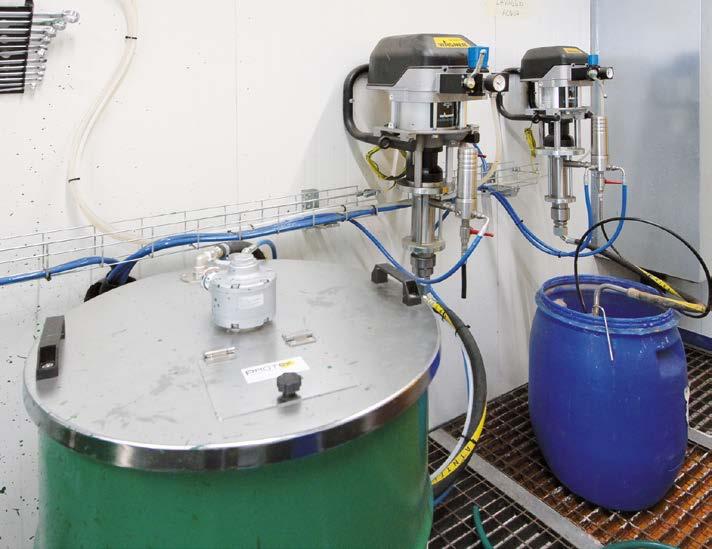
“Since we insourced our coating operations about thirty years ago, on specific parts such as casings, we have been applying a protective layer of approximately 90 µm in one coat by immersing them in a tank filled with a Sherwin-Williams grey onecomponent, acrylic top coat. With the subsequent introduction of a new colour, green, we have also implemented a two-coat cycle in a manual booth using airless application technology. In 2023, when we designed a new robotic system for components requiring higher thicknesses in collaboration with Savim Europe, we also transferred our coating expertise to this line.”
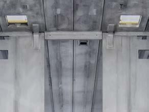
From left to right:
The two coating booths side by side.
A Lesta articulated robot during the application of Sherwin-Williams paint.
The Wagner paint management unit.
The coating of transformers
The production cycle of Newton’s transformers starts with metal sheets with varying thicknesses depending on the power and configuration of the equipment. Their casing design is also tailored to the specific thermal dissipation requirements: their overall dimensions can vary significantly depending on the power required, ranging from a cube measuring approximately 700x700 mm for the most compact models to a size of 1,200x1,200 mm for the largest ones. Metalworking, including laser cutting and welding, precedes the surface treatment phases, defined according to the technical specifications.
After sheet metal processing, the components are washed manually with a high-pressure jet, then shot-blasted in an automatic cluster system with four turbines from OMSG (Villa Cortese, Milan, Italy), and finally blown manually to remove any residues. “We are currently conducting tests with the OMSG team to add a specific product to the grit for further reducing dust residues and improving surface quality,” illustrates Zoncada. After pre-treatment, the parts enter the coating plant designed and installed by Savim Europe.
“Initially,” Zoncada recalls, “the results were not satisfactory: we found numerous film defects such as burn marks, scratches, and overcoating. Moreover, when working with high thicknesses, it was difficult to achieve the 200-µm value required by specifications with a single application.” To address these critical issues, the company sought the advice of Lorenzo Mori, the Sherwin-Williams Company’s General Industrial Agent for Tuscany, Davide Aleotti, Senior Sales Manager - Central Italy GI EMEAI at Sherwin-Williams, and Roberto Martinelli from Protek Srl, a distributor of Wagner systems.
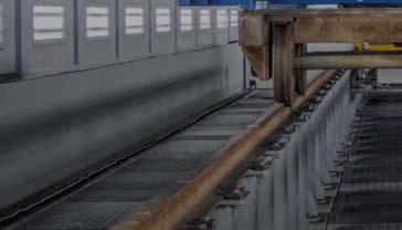
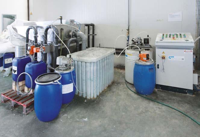
From tof left clockwise:
The skimmer supplied by Hydro Italia Srl to treat the booths’ water curtains. The Savim plant can treat casings up to approximately 1 m3.
The CM Automazione conveyor’s elevator in the loading and unloading station.
“Thanks to their input,” concludes Zoncada, “we have integrated two robotic booths and replaced the airless guns with new AirCoat guns from Wagner, which combine airless technology with air support to ensure better film distension even with high thicknesses.”
“In the AirCoat system,” indicates Martinelli, “the nozzle atomises the material using the airless principle while surrounded by an air curtain, which makes the application process particularly effective. The low air consumption and the soft spray pattern generated by the air curtain allow for optimal results even at low pressures. This is the ideal solution for coating large surfaces on a high number of parts.”
The system designed by Savim thus consists of: a booth for applying the first coat, a flash-off tunnel equipped with an air burner sized for low temperatures, a booth for applying the second coat, and a final drying oven with a 6-metre pre-chamber; the line is complemented by skimmer supplied by Hydro Italia Srl (Medicina, Bologna, Italy) to treat the booths’ water curtains.
The search for the most suitable paint
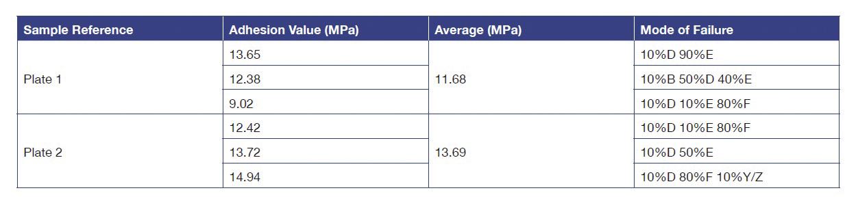
“To provide the most suitable coating for these specific application requirements, Sherwin-Williams Research and Development team reformulated a previously approved product, creating a personalised solution for our long-standing customer Newton,” explains Davide Aleotti. “This has ensured not only the highest quality but also an added value in terms of attention, reliability, and care – a concrete commitment that reflects Sherwin-Williams closeness as a partner, always focused on building relationships of trust and offering tailor-made solutions (Table 1).”
Thanks to the advice of Newton's long-standing paint supplier Sherwin-Williams, the company is now able to achieve thicknesses of 200 μm - covering approximately 90% of its required applicationswithout the need for touch-ups after assembly.
Characteristics
Physical properties
Viscosity (D4/25 °C)(s) 60 – 90
Specific weight (theoretical) (kg/l) 1.24 ± 0.05
Solid content by weight (theoretical)
Solid content by volume (theoretical)
VOC (theoretical) (g/l) 71 Volatile components excluding water (theoretical)
(theoretical)
pH 7.9 – 8.5
Additional information
Application recommendations
Substrate/Pre-treatment
Dilution
Film properties
The surface to be coated must be free of oil, grease, and rust. Suitable pre-treatment is recommended for optimum performance.
Depending on the application system
Gloss (60 degrees) 20 – 30
Theoretical coverage @ 1 µm DFT m²/kg 326
Version 009 00
The benefits achieved
“Thanks to the advice of our long-standing paint supplier SherwinWilliams,” says Zoncada, “we are now able to achieve thicknesses of 200 µm – covering approximately 90% of our required applications – without the need for touch-ups after assembly. In the past, the inability to collect large components that needed retouching in a buffer forced us to send them to the assembly department and return them to the coating department for touchups only once assembled, with a considerable waste of time and logistic effort.” The new cycle, on the other hand, allows for the direct sending of the painted components to assembly and then to shipping, resulting in a significant improvement in efficiency and a substantial increase in production capacity.
“Currently, the power & free conveyor installed by CM Automazione operates with 70 load bars, each with a maximum load capacity of 500 kg,” notes Zoncada, “but the total capacity of the system can reach 92 load bars with approximately 250
Table 1: Data sheet of the product 42301 – F81GUI001 7593-FG
AYW DTM 1K MATT GREEN 6002
metres of chain. The power & free system allows collecting the load bars in buffers, thus compacting the space required, as clearly demonstrated in the oven area. The loading and unloading area is served by an elevator that ensures safe and ergonomic operations. Rotation systems interfaced with the robots in the two booths also contribute to simplifying plant management, allowing for control in the required positions (0°–90°–180°–270°). The result is an optimal coating process, even on complex parts such as fins, which ensures uniform thicknesses of up to 250 µm and avoids the dripping and stress cracking problems that were frequent in the past. We have also reduced the oven dwelling time: one hour at 50 °C is now sufficient to completely dry the coating film.”
Newton Trasformatori’s upcoming projects
In collaboration with Sherwin-Williams and Protek’s technicians, the Newton Trasformatori team is currently working on optimising the plant’s application parameters with particular attention to the robots’ speed, in order to define uniform settings for all fifteen types of products handled by the coating department. “The goal,” says Zoncada, “is to identify a stable configuration that allows us to paint our entire range of components, from casings to covers, while ensuring uniform results even among batches processed at different times.”
Simultaneously, Sherwin-Williams Research and Development team is developing a new grey paint formulation that has the same properties as the green one currently in use and can also be applied in the automatic line with a thickness of 90 µm. That will reduce the load on the dip coating system, increasing overall process efficiency. “This is yet another example of our partner’s ability to respond quickly to our needs,” states Zoncada, “as also demonstrated by the recent creation of a custom, two-component metallic paint designed to meet a specific request from one of our clients.”
The energy challenge of the future increasingly hinges on the ability to anticipate the needs of new markets, from high frequency to direct current management and the choice of cutting-edge materials. Newton has chosen to invest in these areas by combining its consolidated experience with new technologies and skills, adopting a forward-looking approach in which its partnership with Sherwin-Williams marks a further step in a strategy aimed at offering reliable and increasingly high-performance solutions. ‹
One of the types of transformers manufactured by Newton and, from left to right, Davide Aleotti from Sherwin-Williams, Roberto Martinelli from Protek, and Lorenzo Mori from Sherwin-Williams with Lorenzo Zoncada from Newton Trasformatori Spa and Alessia Venturi from ipcm®
Ivano Magnifico and Tommaso Russo, Automa S.r.l. – Ancona, Italy
ivano.magnifico@byautoma.com
The GIANT project revolutionizes cathodic protection by integrating artificial intelligence to significantly enhance safety, efficiency, and sustainability within gas distribution networks. This data-driven system enables a fully digitized operational loop, where monitoring, analysis, and control are seamlessly executed through an integrated digital infrastructure.
The challenges associated with the operation of gas distribution networks are multidimensional due to their complexity: environmental, operational, financial, and safety related. In this context, impressed current cathodic protection (ICCP), used to prevent corrosion of steel pipelines, is crucial to ensure the safety and integrity of the network. Despite the energy consumption and associated CO₂ equivalent emissions, the benefits offered by the ICCP in terms of preventing infrastructure damage and safety (avoiding gas leaks) more than justify the associated environmental costs.
The GIANT (Gas Integrated and Automated Network Technology) project proposes innovative solutions to optimize cathodic protection management, integrating remote monitoring devices, centralized software for data analysis and remote-control systems. In particular, the application of artificial intelligence enables dynamic regulation of the cathodic protection current. This optimized regulation allows a significant reduction in the energy consumption of cathodic protection power supplies, improving their efficiency and contributing to the reduction of CO₂ equivalent emissions.
Thanks to continuous monitoring of field conditions and automatic corrective interventions, the GIANT project enables digital and automated management of cathodic protection. In addition, the introduction of AI-powered predictive maintenance further optimizes the system, predicting failures or inefficiencies before they occur. This approach helps prevent malfunctions and reduce the need for costly field interventions. The complete digitization of the operational management process ensures cost savings, increased productivity and an overall increase in network reliability and security.
Introduction
The continuous enhancement of safety, efficiency, and environmental sustainability in gas distribution networks has become a critical objective for operators and stakeholders. Recent technological advancements, particularly in the fields of automation, data analytics, and artificial intelligence, now enable a new paradigm in network management. Within this context, the GIANT Project (Gas Integrated and Automated Network Technology) offers a forward-looking, integrated solution to address the most pressing challenges in gas distribution-namely environmental impact, operational efficiency, and safety. Digitalization is a transformative process that is redefining industrial systems through interconnected technologies, automation, and real-time data acquisition. It encompasses smart sensors, machine learning algorithms, and big data analytics, all contributing to intelligent and responsive infrastructures. The convergence of these technologies empowers utilities to make
data-informed decisions, streamline operations, and enhance system reliability and resilience.
The GIANT platform represents a comprehensive, data-driven solution that integrates:
Remote monitoring devices, deployed throughout the distribution network, to continuously collect field data (e.g., pressure, odorant levels, electrical parameters).
Remote control systems, capable of executing real-time corrective actions (e.g., adjusting valves, Transformer Rectifiers, or odorant injection units).
Centralised software, designed to analyse and correlate data inputs, enabling intelligent decision-making and automated system regulation.
The system architecture is inherently data-driven: field data acquired through monitoring devices serve as input to an intelligent processing core. This core analyses the data in real time, considering operational constraints and regulatory requirements, and generates output signals that are relayed back to control devices in the field. The platform enables a fully digitized operational loop, where monitoring, analysis, and control are executed through an integrated digital infrastructure.
In particular, the GIANT project enables dynamic and remote regulation of key parameters across the network—namely, pressure, odorant concentration, and cathodic protection current from transformer rectifiers. By maintaining these variables at optimized levels, the system avoids overpressure scenarios, minimizes unnecessary energy consumption by cathodic protection rectifiers (while maintaining the effectiveness), and ensures optimal odorant dosing for safety, without excessive use of odorizing agents.
Furthermore, the platform supports continuous monitoring and real-time anomaly detection, allowing for the immediate execution of corrective actions and predictive maintenance interventions. This capability not only enhances operational continuity and costeffectiveness but also significantly contributes to network safety and environmental performance.
Cathodic protection management within the giant platform
The primary objective of a cathodic protection (CP) system is to maintain the electrochemical potential of buried metallic structures (specifically steel pipelines in gas distribution networks) within the threshold values defined by national and international standards. These reference thresholds are expressed as IR-free potentials, i.e., values measured without the influence of ohmic voltage drops in the surrounding soil.
In practice, however, measurements are often distorted by stray currents from external sources such as adjacent CP systems,
DC and AC rail traction, and high-voltage AC (HVAC) lines. These interferences can cause rectifier control systems to misinterpret elevated potential readings, resulting in the delivery of excessive current.
This leads to several adverse effects:
Risk of overprotection on pipelines with high-performance coatings (e.g., three-layer polyethylene), potentially causing:
- Coating degradation, due to elevated current densities
- Accelerated AC corrosion, in areas exposed to alternating current interference
Mutual interference among nearby CP systems, potentially requiring further current increases
Increased CO₂ emissions, due to unnecessary energy consumption
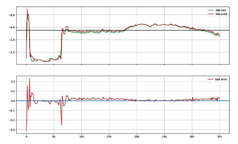
Higher operational costs, linked to excessive power usage. To mitigate these issues, accurate IR-free measurements are essential. This is achieved using embedded monitoring systems with reference electrodes and coupons capable of performing continuous instant-off readings, typically at one-second intervals. These real-time, high-frequency measurements enable precise assessment of actual pipeline polarization, allowing rectifiers to regulate output based on true protection conditions, ensuring compliance while minimizing energy waste.
The GIANT platform addresses these challenges by integrating CP management into a centralized, intelligent system. It combines:
A physical layer, consisting of data loggers, coupon-equipped reference electrodes, and remotely controllable rectifiers
A digital layer, featuring centralized software that applies datadriven algorithms to analyse field data and issue corrective actions in real time.
Through remote acquisition of instant-off potentials and direct integration with rectifier control units, the system enables remote configuration of strategies and setpoints. Once programmed, rectifiers can operate autonomously, maintaining defined control logic even in the absence of active communication.
The platform supports multiple configurable operating modes:
Constant Current Mode: delivers a fixed output current
Variable Current Mode: maintains a target On potential, with optional base current constraints
Constant local IR-Free Potential Mode: maintains a specified Eoff value, measured via coupon, with optional current limits to improve control stability in systems with multiple rectifiers.
In addition to these modes, the GIANT platform offers advanced remote regulation capabilities. Rectifiers can adjust output based on an Eoff target measured at a remote critical point, typically the least electronegative location in the network. This requires a continuously online, addressable monitoring device capable of real-time instant-off readings.
The regulation process consists of the following steps:
Activation and adjustment: the supervisory platform assigns a remote monitoring point to a rectifier and initiates current regulation to reach the specified Eoff target.
- If the target is achieved within the defined actuation time and tolerance (dead band), the rectifier reports success.
- If not, it reverts to the previous state, logs the failed attempt, and retries after a configurable delay.
All events are logged and communicated for full traceability.
To enable effective and continuous remote regulation of cathodic protection systems a critical enhancement involves upgrading the power supply at remote monitoring points, particularly those currently operating on standalone battery packs.
Periodic verification: at scheduled intervals (e.g., every few minutes or hours), the system revalidates the Eoff value at the remote point. If deviations are found, the regulation cycle is repeated.
Control strategy between cycles: between verifications, the rectifier switches to a local fallback mode based on the availability of a local probe:
- With local coupon: enters Constant Local IR-Free Potential Mode, using the latest successful Eoff value
- Without local coupon: switches to Variable Current Mode, using the last corresponding Eon value, or Constant Current Mode, using the last corresponding I value.
This adaptive control architecture ensures accurate, real-time optimization of CP output. It enhances energy efficiency, minimizes mutual interference, extends asset longevity, and ensures regulatory compliance, all while responding dynamically to changing field conditions.
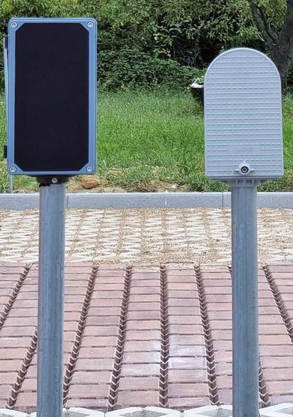
Solar panel
To enable effective and continuous remote regulation of cathodic protection systems, as described in the previous section, a critical enhancement involves upgrading the power supply at remote monitoring points, particularly those currently operating on standalone battery packs. These locations, often situated at the most electrically disadvantaged or interference-prone sections of the network, require frequent acquisition and transmission of IRfree potential data to support dynamic regulation.
Where compatible with landscape and regulatory constraints, the introduction of solar-powered energy systems represents a significant technological advancement. The integration of a photovoltaic panel with an onboard rechargeable battery enables continuous power supply to the monitoring device, ensuring uninterrupted operation of the embedded modem. This configuration allows the system to maintain persistent connectivity with the supervisory platform, increasing the frequency and
reliability of data updates from the field. The use of solar power (example in Figure 1), coupled with a single high-capacity rechargeable battery, extends the maintenance-free operational lifespan of the monitoring unit to over ten years. This improvement translates into a drastic reduction in maintenance requirements, lowering the average number of battery replacements from approximately three per decade (with traditional battery packs) to zero over the same period.
In parallel, this also yields a substantial reduction in battery handling and disposal activities, with associated environmental and logistical benefits. The estimated decrease in battery pack turnover corresponds to an over 18-fold reduction in associated operational interventions and waste generation.
From an environmental perspective, the impact on carbon emissions is particularly notable. The Table 1 compares the CO₂ equivalent emissions associated with different power configurations across a representative fleet of 300 monitoring devices:
Table 1 – Comparative analysis of CO2 equivalent emissions associated with different power configurations across a representative fleet of 300 monitoring devices.
This data highlights a more than 70-fold reduction in CO₂ emissions when transitioning from conventional battery packs to a solar-powered, rechargeable system.
Furthermore, when integrated with the GIANT platform’s remotecontrol architecture, solar-powered monitoring points facilitate true dynamic current regulation of cathodic protection rectifiers. Continuous, real-time verification of IR-free potentials at critical nodes allows rectifiers to adjust output current in response to actual protection levels, supplying only the minimum necessary current required to maintain compliance with protection criteria across the network.
The result is a tangible optimization of energy use across cathodic protection systems: reducing total electricity consumption, minimizing environmental impact, and extending the service life of both physical infrastructure and power components.
Figure 1 - Test post equipped with compact Solar Box.
AI for smart cathodic protection management
As gas distribution networks grow in complexity and regulatory requirements become more stringent, the integration of Artificial Intelligence (AI) is emerging as a key enabler in nextgeneration Cathodic Protection (CP) systems. The GIANT platform incorporates AI-powered control logic to support predictive, adaptive, and coordinated regulation throughout the CP infrastructure. This approach surpasses traditional control methods by leveraging real-time analytics, neural algorithms, and predictive modelling.
The use of AI in cathodic protection management enables the system to:
Perform real-time analysis of high-frequency field measurements
Apply predictive models for both regulation and maintenance tasks
Continuously estimate the optimal network operating state, accounting for various input variables and constraints (e.g., system topology, regulatory thresholds, environmental conditions)
Dynamically implement corrective actions by adjusting the operational parameters or setpoints of rectifiers.
To transition from a static, point-focused control strategy to a globally optimized regulation model, the AI engine processes a comprehensive dataset, including:
IR-free Eoff potentials sampled in real time (typically at 1 Hz) from strategic locations such as test stations, railway crossings, transformer-rectifier (T/R) units, and drainage points
Coupon polarization current densities, both DC and AC components, also sampled at high frequency
Output parameters of rectifiers (DC/AC voltage and current), used to evaluate the performance of groundbeds and rectification units
Supplementary Eon potential values from field surveys or permanently monitored points to enhance model accuracy
System topology and asset metadata, including pipeline surface area, CP zone configuration, T/R distribution, and coating condition
Temporal context such as seasonality, weekday/holiday classification, and historical behaviour
Meteorological and environmental data (temperature, humidity, rainfall).
The AI module synthesizes this information to regulate current output across all CP rectifiers with the following objectives:
Ensure compliance with applicable standards and regulations
Maintain the minimum effective current needed for corrosion protection while reducing energy consumption
Anticipate performance deviations due to recurring or seasonal effects, enabling proactive adjustments
Responding to transient environmental conditions (e.g., rainfall, temperature changes) that affect system polarization
Balance current loads between rectifiers in meshed networks, minimizing wear on individual units and optimizing groundbed usage.
Optimal setpoints and regulation strategies are computed in real time and applied through two operational modes:
Semi-automatic mode: AI-generated actions are reviewed by CP technicians before execution. This mode is ideal during the initial deployment phase or where manual oversight is preferred.
Fully automatic mode: the AI autonomously adjusts rectifier parameters without human intervention, with all actions logged for traceability and diagnostics.
This adaptive, intelligent regulation approach enables significant improvements in system efficiency, diagnostics, and maintenance scheduling while maintaining full compliance with corrosion protection standards. It represents a shift from reactive to predictive, data-driven CP system management.
AI models for predictive analytics in CP systems
A recent study (1) conducted in collaboration with the “Università Politecnica delle Marche” (Ancona) evaluated the performance of different AI models for forecasting cathodic protection voltage values. Two models showed promising results:
Rolling window method: a local, runtime forecasting approach that applies regression to a moving time window of fixed length over historical pipe potentials data. At each iteration, the model predicts future values by extending the fitted curve.
LSTM neural networks: a generalized modelling technique that uses Long Short-Term Memory networks trained on historical pipe potentials data. Both univariate (potential only) and multivariate (potential and CP current) configurations were evaluated. The models were tailored individually for each measurement point, requiring customized architecture, hyperparameters, and training epochs.
Upon comparing performance metrics across various measurement points, it was found that the multivariate LSTM model using a 45-sample rolling window produced the most accurate forecasts (Figure 2). However, the rolling window model is simpler and more suitable in scenarios with limited historical data. Its main limitation is increased prediction error during sudden or large voltage shifts across time.
By leveraging both real-time and historical data, correlated with environmental conditions and calendar patterns, AI algorithms can generate predictive models of CP system behaviour. These models detect deviations from expected performance, allowing early identification of anomalies before they escalate into alarm conditions.
In contrast, the LSTM model offers higher accuracy but demands historical data and per-point customization, including fine-tuning of layers, learning rates, and epochs. Improved granularity, denser sampling, and the inclusion of contextual data (e.g., weather, soil resistivity) could enhance both models’ performance. Such inputs could also support generalization, potentially allowing a shared neural network to predict values across multiple measurement points. If richer data and corrosion-related indicators are available, these models could be extended to predict behaviours in more complex systems (e.g., those with multiple T/Rs) which would also require detailed topological data to capture current flow directionality. Below is an example of forecast vs. actual pipe potential values using the multivariate model.
AI for predictive maintenance
By leveraging both real-time and historical data, correlated with environmental conditions and calendar patterns, AI algorithms can generate predictive models of CP system behaviour.
These models detect deviations from expected performance, allowing early identification of anomalies before they escalate into alarm conditions. Continuous data acquisition combined with machine learning enables constant refinement of these models, enabling forward-looking diagnostics and maintenance scheduling.
Figure 2: Trend of the fifth forecast day - multivariable model and window 45 days.
Predicting groundbeds end-of-life
In urban gas distribution networks, replacing exhausted groundbeds involves significant delays due to permit acquisition. Predicting end-of-life in advance prevents emergency interventions that compromise CP current delivery.
As groundbeds degrade, circuit resistance increases, forcing the rectifier to raise output voltage to maintain current levels. When rectifiers reach the 50V DC limit, they can no longer deliver the required current. Using historical current and voltage trends, and applying Ohm’s Law, the system estimates circuit impedance and forecasts the groundbed’s remaining lifetime.
As illustrated in Figure 3, seasonal variations are overlaid by a degradation trend caused by groundbed wear. In the case shown, the AI model could predict the failure point up to 18 months in advance, enabling proactive replacement.
Reference electrode efficiency
A critical issue in CP effectiveness is the potential drift of reference electrodes at measurement points. These deviations can produce seemingly valid readings, leading to incorrect regulation or, in severe cases, significantly skewing the control logic of nearby rectifiers. By analysing voltage trends, historical data, and environmental conditions, the system generates predictive models that associate expected potentials with specific rectifier currents. Deviations from this model, absent actual fault conditions, can trigger alerts indicating reference electrode degradation.
Detection of other anomalies
Using predictive models derived from measured parameters, the
system can identify additional anomalies beyond those described above, including:
Unintended contact with third-party structures: when measured potentials diverge from the model but coupon polarization currents remain consistent with the new state, the system may detect unintended metallic contact—even if no obvious symptoms are present.
Coupon efficiency loss: inconsistent Eoff potential readings— divergent from historical patterns—combined with abnormal polarization current behaviour may suggest issues such as copper sulphate contamination or soil displacement, leading to loss of electrolytic contact.
Conclusions
The GIANT project represents a significant step forward in the evolution of cathodic protection (CP) systems, addressing longstanding challenges related to efficiency, safety, cost, and sustainability. By integrating artificial intelligence with remotely controllable infrastructure, the platform enables a shift from traditional reactive maintenance to a fully proactive, data-driven management approach. This transformation is not limited to technological enhancement alone but extends to operational philosophy and organizational processes as well.
One of the most immediate and impactful benefits of the GIANT system lies in its contribution to safety. The ability to regulate and intervene remotely, either in semi-automatic or fully autonomous mode, eliminates the need for routine on-site operations and allows for timely responses in potentially hazardous scenarios. This inherently reduces the exposure of field personnel to risk,
Figure 3 - Trend of a groundbed performance over 8 years.
cuts down on unnecessary travel, and prevents accidents related to emergency interventions. The improved response time, coupled with continuous monitoring and predictive capabilities, contributes to a safer overall operating environment.
Economic efficiency is another critical outcome. By leveraging real-time analytics and predictive modelling, the system can reduce both direct and indirect operational costs. Optimized energy consumption through intelligent rectifier control, reduced gas losses thanks to early anomaly detection, and the minimization of field interventions translate into substantial savings. These benefits are not only measurable in financial terms but also reflect a more sustainable use of resources.
Equally important is the enhanced level of control the GIANT platform offers. With the ability to perform real-time or scheduled adjustments based on detailed consumption and performance profiles, operators gain unprecedented visibility and authority over the CP network. This level of control supports more balanced operation across infrastructure, ensuring that performance demands are met without overburdening specific components. It also improves compliance with industry standards and facilitates better coordination across distributed assets.
From an environmental perspective, the system aligns with growing regulatory and societal pressures to reduce greenhouse gas emissions. Intelligent rectifier control ensures that only the minimum necessary current is delivered, enough to maintain effective protection without wasteful overcompensation. This approach complies with established standards, thereby contributing to a greener and more sustainable infrastructure. Ultimately, the GIANT project exemplifies how advanced digital technologies (particularly AI) can be harnessed to modernize critical infrastructure systems. It demonstrates that innovation in cathodic protection is not just possible, but necessary, in order to meet the evolving demands of safety, efficiency, and
environmental responsibility. By transforming CP into a smart, predictive, and remotely managed function, GIANT paves the way for a new standard in infrastructure integrity management. What emerges from this work is not just a collection of technological advancements, but a coherent vision of the future of CP systems: one in which intelligence, automation, and sustainability are deeply intertwined. The GIANT platform does not simply improve what already exists—it redefines what is possible.
Bibliography
[1] Beatrice Molitierno (2023). Development of a data-driven supervision module for cathodic protection systems in gas distribution networks. ‹
What emerges from this work is not just a collection of technological advancements, but a coherent vision of the future of CP systems: one in which intelligence, automation, and sustainability are deeply intertwined. The GIANT platform does not simply improve what already exists—it redefines what is possible.
NAVAL SURFACE WARFARE CENTER TAPS CLEMSON UNIVERSITY
TO DEVELOP VIRTUAL REALITY-BASED CORROSION TRAINING FOR
SAILORS
by Thomas McMahon,
Naval Surface Warfare Center, Port Hueneme Division Public Affairs nswcphd_pao@us.navy.mil
Training sailors to tackle corrosion on Navy vessels is the goal of a new project that Naval Surface Warfare Center, Port Hueneme Division (NSWC PHD) has launched with Clemson University in Clemson, South Carolina, United States.
The Port Hueneme, California-based command recently selected the public research institution in Clemson to develop virtual reality (VR)-based training targeting shipboard corrosion under the Naval Engineering Education Consortium (NEEC) program. A $150,000-per-year NEEC grant will fund the work at Clemson. NSWC PHD can renew the agreement for up to three years.
Armen Kvryan, the command’s corrosion lead and NEEC director, said there’s a need for training modules tailored to sailors, who are on the front lines of battling saltwater corrosion in the fleet. Corrosion costs the U.S. Navy approximately $8 billion per year, more than half of which is related to ships and other naval vessels, according to Kvryan.
Courses on corrosion, which Kvryan described as “a difficult subject,” typically require prior knowledge in other areas, like material science and chemistry. The new training will drill down on the basics of corrosion and present it in an easy-to-understand manner for naval personnel who don’t have an educational background on those topics.
Kvryan said he expects the content to delve into identifying different types of corrosion — for instance, an orange spot is likely iron rust, while a white spot is probably aluminium corrosion — and how to treat them. The course would also cover pertinent topics like paints, coatings and protective oxidation layers — which workers often mistakenly scrape off, leaving bare metal that is more susceptible to corrosion.
The new training program will focus on the fundamentals of corrosion, presenting them through virtual reality in a way that is accessible to naval personnel without a technical background.
This enhanced knowledge would help the Navy save time and money on dealing with corrosion, Kvryan said, and it would enable sailors to more accurately characterize corrosion-related issues when they communicate with In-Service Engineering Agent personnel. “It will get to the essentials of what sailors need to know about corrosion, and deliver that in a very short time frame,” he said. “My goal is to give them, in one day, 50% more than they knew previously.”
While Kvryan knows corrosion — he holds a doctorate in the subject — he said he has struggled to teach it to sailors in an engaging way, which is where the partnership with Clemson comes into play.
Corrosion costs the U.S. Navy approximately $8 billion per year.
Immersive learning
Clemson brings expertise on both corrosion and VR to the NEEC project, according to Kvryan. The university offers courses on those subjects and operates a Corrosion Research Laboratory, which works on developing new technologies to mitigate damage due to corrosion.
“We know corrosion; we know VR,” said Amir Poursaee, a Clemson professor of civil engineering and materials science and engineering, and director of the Corrosion Research Laboratory. “We’re going to combine our forces for a new methodology to deliver a dynamic corrosion course.”
The VR aspect will provide “immersive learning” for sailors, according to Anand Gramopadhye, dean of Clemson’s College of Engineering, Computing and Applied Sciences1 and principal investigator of the organization that houses the Clemson University Center for Workforce Development. “We can expose them to different scenarios where they have to make a judgment and use tools,” Gramopadhye said. “The idea is creating a skilled workforce that is consistently trained on the same data sets.”
1 https://www.clemson.edu/cecas/
This enhanced knowledge would help the Navy save time and money on dealing with corrosion and it would enable sailors to more accurately characterize corrosion-related issues.
Initially, sailors involved in ship maintenance would take the corrosion course on VR headsets while visiting NSWC PHD. The goal would be to eventually expand its availability to other ports, Kvryan said.
Another factor in selecting Clemson was its plan for utilizing students in the project, according to Kvryan. That includes engaging with the U.S. Department of Veterans Affairs, the Department of Labor’s Veterans’ Employment and Training Service, and other organizations in an effort to involve veteran students. Poursaee said he expects to hire two to three students to develop the corrosion curriculum and the VR component. The team will include graduate and undergraduate students, Gramopadhye added.
Kvryan said he was also impressed by the university leaders’ approach to the project as a partnership rather than a transactional relationship.
“They said let’s do this together,” Kvryan said. “They genuinely want to do good and help the warfighter.”
That motivation aligns with Clemson’s many years of experience working with all branches of the U.S. military, according to Gramopadhye. “We have a deep history of Department of Defense research,” he said.
Tapping academia
The NEEC program funds research projects at all 10 Naval Sea Systems Command warfare centres and involves more than 50 universities across the country.
NSWC PHD requests proposals for NEEC projects via a procurement tool called broad agency announcements. A selection committee at the command reviews and grades the proposals to determine the winner. The corrosion project attracted proposals from about 20 universities.
Kvryan said that NEEC is an avenue for NSWC PHD to tap academia for efforts that the command doesn’t have the bandwidth to pursue in-house — particularly in the realm of research and development.
Another aim of the program is to develop and attract new professionals into the technical fields associated with U.S. Navy ships and submarines. ‹
Armen Kvryan, the director of the Naval Engineering Education Consortium, is teaming up with Anand Gramopadhye, dean of the College of Engineering, Computing and Applied Sciences, to tackle corrosion.
Customers with assets exposed to harsh environments or operational wear and tear often seek coatings that can provide a robust defence against the relentless forces of degradation. The development of advanced protective coatings with superior anti-corrosion properties is crucial for an extended lifecycle of metal structures.
SPHERILEX® AC 45 and SPHERILEX® AC 45 HS are calcium silicate-based anti-corrosive pigments, developed to meet the demand of superior anticorrosion performance. These pigments consist primarily of silica (94%) and calcium oxide (6%). Their spherical morphology not only facilitates easier and more even dispersion compared to angular alternatives but also minimizes aggregation, enhancing dispersion stability. This characteristic ensuring consistent protection across the substrate.
The anti-corrosive pigments showed exceptional performance in various formulations from waterborne, to solvent borne and powder coating formulations.
Table 1 - Corrosion resistance after 1500 hours salt spray testing according to ASTM D1654 in a water-borne 2K epoxy primer.
Table 2 and figure 1 - Corrosion resistance after 1500 hours salt spray testing according to DIN EN ISO 12644 in a solvent borne 2K epoxy primer.
Table 3 - Mass loss after 500 cycles Taber abrasion testing in a water-borne 2K epoxy primer.
When used in water-borne 2K epoxy primers SPHERILEX® AC 45 and SPHERILEX® AC 45 HS demonstrated significant corrosion resistance, as evidenced by salt spray tests according to ASTM D1654 conducted over 1500 hours (Table 1).
One of the standout features of these pigments is their ability to perform at half the dosage level of traditional pigments. This not only reduces the material cost but also the environmental impact, aligning with the growing demand for sustainable industrial practices. The test results of salt spray testing according to DIN EN ISO 12944 after 1500 hours in a solvent borne 2K epoxy formulation showed reduced corrosion creep and rust grades compared to traditional zinc phosphate formulations (Table 2 and Fig. 1).
In abrasion resistance tests, SPHERILEX® AC 45 and SPHERILEX® AC 45 HS showed significantly lower mass loss compared to blank samples, indicating enhanced film hardness and durability. This is particularly beneficial for applications where mechanical wear is a concern. One of the most compelling features of these products is its improved environmental footprint compared to traditional anti-corrosion pigments (Table 3). Unlike chromate-based pigments, which are known for their carcinogenic potential, or phosphate-based pigments, which pose environmental concerns due to their impact on aquatic life, calcium silicate pigments offer a safer alternative. The formulation of SPHERILEX® AC 45 and SPHERILEX® AC 45 HS does not impact hazardous labelling, making it a preferable choice for industries aiming to reduce their ecological impact while maintaining high performance standards. They are globally applicable as they are registered across multiple international inventories.
SPHERILEX® AC 45 and SPHERILEX® AC 45 HS represent a significant advancement in anti-corrosion technology. Their innovative composition and morphology offer a compelling alternative to traditional pigments, providing enhanced performance, reduced environmental impact, and cost-effectiveness. As industries continue to seek solutions that balance performance with sustainability, these calcium silicate-based pigments are poised to become a preferred choice for anti-corrosion applications across various sectors. ‹
BENEFITS AT A GLANCE
Versatile anti-corrosion pigments or waterborne, solvent borne and powder coating products
Superior anti-corrosion performance
The spherical shape could enhance film hardness and abrasion resistance
Easier to formulate at higher loading levels (as needed) because of its spherical nature
Label-free product.
Celebrating 50 years of flame retardants: Exolit™ AP leads the way to a more sustainable future
by Clariant International Ltd.
Clariant celebrates a significant milestone in 2025: 30 years since its foundation, and 50 years of Exolit AP. The successful launch of the melamine-free Exolit AP in 2024 represents a breakthrough as an SVHC-free innovation, while maintaining superior fire resistance performance.
In 2025, Clariant is proud to celebrate a significant milestone: 50 years of Exolit AP flame retardants protecting lives and property around the world.
Based on advanced ammonium polyphosphate (APP) technology, these pioneering flame retardants have become the industry benchmark in a wide range of applications, including intumescent coatings, fire barrier sealing systems, thermoset composites for e-mobility battery housings and coatings, rigid polyisocyanurate (PIR) insulation foams and more.
As Clariant marks this golden anniversary, it is not just celebrating past achievements but actively shaping the future of fire protection.
A legacy of innovation
Since producing the first batch of Exolit AP at the Knapsack site in Germany in 1975, the Exolit AP product line has pioneered flame retardant technology. What began as a groundbreaking solution has evolved into a comprehensive portfolio that sets industry standards for performance and reliability.
The recent launch of a melamine-free Exolit AP grade demonstrates how this spirit of innovation continues today.
Innovation for today and tomorrow
The successful launch of melamine-free Exolit AP marks a significant step forward in more sustainable flame retardant technology.
This SVHC-free solution, without the addition of melamine, demonstrates Clariant’s commitment to meeting stringent safety and sustainability demands while maintaining superior fire resistance across multiple Passive Fire Protection (PFP) solutions such as fire stop systems and intumescent coatings, as well as flame-retardant applications like insulation panels. This development responds to the rising demand from healthand sustainability-conscious consumers and brands, including those who are actively seeking safer alternatives to products containing substances of concern.
Similar to the growing adoption of PFAS-free alternatives across various markets, there is a clear shift in purchasing behaviour towards safer solutions in PFP.
Exolit AP 435: same trusted performance, now even better for tomorrow
Building on this momentum, Clariant is excited to preview the next evolution in the journey towards melamine-free fire protection: an enhanced version of the trusted Exolit AP 435. This evolution maintains the exceptional performance characteristics in water-based formulations that have made
"Through
changing times and evolving industry needs, Exolit AP has remained at the forefront of innovation. From its origins in Hoechst AG to becoming a cornerstone of Clariant’s portfolio in 1997, each decade has brought new challenges and achievements. The introduction of Exolit AP 462 in 1983 marked our first major breakthrough in encapsulated ammonium polyphosphate technology, setting new industry standards for performance and reliability
Achim Hennemann, Global Market Manager Passive Fire Protection
Exolit AP 435 the industry benchmark for shelf-life stability, while incorporating forward-thinking improvements to meet future regulatory requirements, all without compromising on fire protection performance.
The power of partnership
Clariant’s success story is built on strong partnerships with customers, many spanning generations. In the continued development of next-generation solutions, Clariant is engaging with forward-thinking companies interested in shaping the future of sustainable flame retardants. This collaborative approach ensures that innovations align perfectly with market needs while maintaining high-performance standards.
To show that significant innovations are best achieved through partnership, Clariant is actively seeking development partners who share the vision for more sustainable fire protection and want to be at the forefront of industry innovation. This collaborative approach helps refine solutions while ensuring they meet realworld performance demands.
Milestones that matter
Clariant’s 50-year journey has been marked by significant breakthroughs:
1975: Introducing Exolit AP 422 flame retardant.
1983: Launching Exolit AP 462, encapsulated ammonium polyphosphate (APP).
1990s: Development of specialized solutions for intumescent coatings.
2000s: Strategic expansion of intumescent coatings market.
2015: Launching Exolit AP 435, setting new standards in viscosity control.
2024: Introduction of the very first melamine-free Exolit AP.
2025: Continuing development of next-generation solutions.
"Through changing times and evolving industry needs, Exolit AP has remained at the forefront of innovation. From its origins in Hoechst AG to becoming a cornerstone of Clariant’s portfolio in 1997, each decade has brought new challenges and achievements. The introduction of Exolit AP 462 in 1983 marked our first major breakthrough in encapsulated ammonium polyphosphate technology, setting new industry standards for performance and reliability", said Achim Hennemann, Global Market Manager Passive Fire Protection.
Today, this legacy of innovation continues. “The launch of melamine-free Exolit AP represents more than just a new product,” explained Adrian Beard, Global Industry Market Manager Flame Retardants. “It embodies our commitment to
combining five decades of expertise with tomorrow’s sustainability demands.”
The road ahead
As Clariant looks to the next 50 years, its commitment to innovation remains stronger than ever. The success of the very first melamine-free Exolit AP grade and the evolution of Exolit AP 435 demonstrate how the company can meet evolving industry needs while maintaining the high-performance standards that have defined Clariant’s products for half a century.
Stefan Brejc, Global Vice President Segment Coatings & Adhesives proudly stated, “The same pioneering spirit that drove our first innovations in 1975 still drives us today. As we celebrate this golden anniversary, we’re not just looking back at 50 years of achievement, we’re building on this foundation to create the next generation of more sustainable flame retardants.” ‹
Clariant celebrates a significant milestone in 2025: 30 years since its foundation and 50 years of Exolit AP. These anniversaries are closely linked, as Exolit AP was originally developed by Hoechst AG, whose specialty chemicals business was acquired by Clariant in 1997.This acquisition not only expanded Clariant's global presence but also brought Hoechst's innovative portfolio into the Clariant family. It's important to note that while Clariant was officially founded in 1995, the legacy of Exolit AP dates back to Hoechst AG, making 2025 a double celebration of innovation and heritage for both Clariant and its renowned flame retardant additive. This context highlights the shared heritage and provides clarity for readers.
Micro-Corrosion Inhibiting Coatings Solve A Wide Variety Of Corrosion Problems!
40 years of performance Hutton TLP case study and the impact of highly loaded lamellar
glass flake in offshore coating
edited by AkzoNobel N.V.
This paper investigates the long-term performance of Interzone® 1000, a high-build epoxy coating containing >30% lamellar glass flake, through both laboratory testing and a 40-year offshore case study (Hutton TLP). Results confirm that high glass flake loading significantly enhances abrasion, impact resistance, and long-term corrosion protection. Field analysis after four decades shows minimal degradation, excellent adhesion, and preserved barrier properties, supporting the coating’s suitability for extended offshore service life.
In the offshore environment, both for Oil & Gas (O&G) and wind energy sectors, there is an increasing need to extend the lifetime of assets to 40 years or more. The main drivers of this change are to reduce the need for expensive and hazardous maintenance in difficult-to-reach offshore locations and to minimize the environmental impact these assets have over their lifetime.
Currently, there are no recognised industry standards for accelerated testing beyond 30 years. This leaves paint manufacturers with the critical question: “How do we prove our coatings can last beyond 40 years?”.
AkzoNobel’s approach to answering this question involves examining long-standing real-world examples of assets and utilising both existing and new testing methods to determine the expected durability of its coatings.
Two recognised accelerated testing approaches used in the industry to determine the lifetime expectation of a coating system for splash zone and immersed areas are Water Immersion and Corrosion Creep at the Scribe.
A. Water immersion
Long term water immersion tests and cathodic disbondment tests form part of recognised standards such as ISO 12944 and Norsok M501. Newer standards such as ISO 24656:2022, provide guidance for long term durable coating systems for both immersed and partly immersed areas offshore and recommend for the use of epoxy coatings with highly loaded lamellar glass flake (>20%) for the longest durability (Fig. 1 and Table 1).
Figure 1 - Illustration of water permeability.
Table 1: Extract from ISO 24656.
B. Corrosion Creep at the Scribe
Accelerated corrosion tests such as ISO 12944 and Norsok M501 utilise corrosion creep at the scribe along with set prequalification criteria. These methods measure the performance once the coating has been artificially damaged and once the steel is exposed, it will start to corrode, and the coating’s role is to slow down the expansion and spread of the corrosion due to under film corrosion. The main function of a coating in the splash zone or immersed area is to ensure appropriate barrier protection and to prevent the external environment from causing steel metal loss. One way to achieve this is to ensure that the coating remains intact for as long as possible, thereby ensuring and prolonging low permeability and high barrier properties.
This paper explores the durability of Interzone® 1000 when varying the loadings of lamellar glass flake. The loading of lamellar glass flake was varied then subjected to a range of performance tests to ascertain a comparison versus the standard commercially available product.
In addition, a review of how a commercially available product performed in an offshore real-world environment via a 40year case study, evaluating visual appearance, adhesion, cross-sectional optical microscopy, and electrical impedance spectroscopy (EIS).
2. Glass flake content study – part 1
2.1. Introduction
Interzone 1000 is one of the longest-serving products within the International® range of protective coatings. It is designed for the most aggressive offshore environments, such as underdeck areas, splash and tidal zones, and sub-sea areas. Interzone 1000 offers an excellent combination of corrosion protection and resistance to mechanical damage in both atmospheric and immersed environments. It boasts an extensive track record, including 40year performance testimonials, which is unmatched in the industry. In these aggressive environments, Interzone 1000 typically utilizes high Dry Film Thickness (DFT) combined with a high loading of glass fake. Interzone 1000 contains >30% corrosion and chemically resistant lamellar structure glass flake in the cured film. This glass flake significantly contributes to the high barrier against moisture ingress and reinforces the dry film, providing excellent resistance to mechanical damage such as impact and abrasion. Furthermore, the ISO 24656:2022 standard (Cathodic Protection of Offshore Wind Structures) recommends a high-build, glassflake epoxy or polyester material containing at least 20% non-micronized glass flake for the longest service life. This recommendation has led to questions about the glass flake loading level in Interzone 1000, with some competitors claiming that the >30% lamellar structure glass flake level is excessive.
The aim of Part 1 of this study is to investigate the impact and abrasion resistance of Interzone 1000 when compared to variants with reduced levels of lamellar structure glass flake. The data from this work will show whether this reduction significantly affects the impact and abrasion resistance.
2.2. Test program
Variants of Interzone 1000 were formulated with glass flake levels varying from 20% down to 0% in the dry film. These were tested alongside the control formulation -Interzone 1000 - with its >30% loading level in the dry film.
This resulted in the following 4 variants being tested:
Interzone 1000 (standard product with glass flake loading at >30%)
Interzone 1000 (reduced glass flake loading to 20%)
Interzone 1000 (reduced glass flake loading to 10%)
Interzone 1000 (No glass flake loading – 0%).
There are numerous methods for assessing the abrasion resistance of a coating system. The most extensively used is the Taber Abrasion test. However, there are concerns that this test does not provide an accurate gauge of a coating’s abrasion resistance.
In Part 1 of this study, focus has been to evaluate performance in the following tests:
Shear Box (BS1377 Part 7: Method 5)
Gardner Impact (ASTM D2794).
In addition, the mechanical properties, such as tensile strength and elongation were investigated for the formulation variants to ascertain whether this data correlated with the abrasion resistance. The Cyclic Aging Test (ISO 12944-9) was also included in the test program to understand whether the reduction in glass flake has a detrimental effect on corrosion at a scribe. Results from this study will be released in future parts.
THE MAIN FUNCTION OF A COATING IN THE SPLASH ZONE OR IMMERSED AREA IS
TO ENSURE
APPROPRIATE BARRIER PROTECTION AND TO PREVENT THE EXTERNAL ENVIRONMENT FROM CAUSING STEEL METAL LOSS.
ONE WAY TO ACHIEVE THIS IS TO ENSURE THAT THE COATING REMAINS INTACT FOR AS LONG AS POSSIBLE, THEREBY ENSURING AND PROLONGING LOW PERMEABILITY AND HIGH BARRIER PROPERTIES.
2.3. Test results
2.3.1. Shear
box
- BS 1377 Part 7: Method 5
Abrasive cargoes such as bauxite, iron ore, and coal are placed in a shear box, which is then positioned onto a coated steel panel with a set pressure ranging from 300 kPa to 1200 kPa. The panel is dragged under the cargo at a set rate (up to 1.1 mm/min) while the pressure is applied. The coating loss or damage is then measured and categorized as either cohesive damage (damage within the coating) or damage down to the steel substrate (where the underlying steel is exposed to atmospheric conditions, Fig. 2).
This test has been shown to differentiate coatings in a manner similar to in-service conditions and has been used for cargo settling and ice-breaker coating assessments. It was originally derived from civil engineering purposes for the classification of soils and clays (BS 1377 Part 7: Method 5). Since Interzone 1000 sustains minimal damage, particularly down to the underlying steel substrate (which could lead to corrosion), the test parameters were slightly modified to investigate the coating’s endurance and to differentiate the various loading levels of lamellar glass flake:
The cargo chosen was iron ore, the most aggressive cargo available for this test method
The pressures were significantly increased from 300 kPa to 900 kPa and to a maximum of 1200 kPa.
In addition to the standard scheme thickness (2x 500µm DFT), a single scheme thickness was investigated.
Repeats of the test were carried out on panels to determine whether a second run would significantly impact the abrasion resistance, given the likely DFT loss from the first run.
The typical scheme thickness for Interzone 1000 is 1000 µm (two coats at 500 µm per coat).
Reducing the scheme thickness to 1 x 500 µm increases the likelihood of abrasion damage reaching the underlying steel substrate thus being able to better visually correlate performance across the glass flake loading levels.
Duplicate panels were prepared as a single-coat scheme (1 x 500 µm DFT). Half of these panels were tested using iron ore at 900 kPa, and the remaining panels were tested at 1200 kPa before being assessed for abrasion damage. The graph in Fig. 3 shows how the coatings performed at the two different pressures. The most critical performance parameter is the damage down to the steel substrate, as this could lead to corrosion of the structure. The damage down to steel was plotted against the glass flake loading. The test at 900 kPa shows a significant difference between the highest and lowest loading levels of glass flake; the damage down to the steel substrate ranges from 0% to almost 1% when the glass flake is removed in the standard Interzone 1000 formulation. The damage to the 10% and 20% glass flake loading level is so low that there is no significant difference between these
coatings. The test carried out at an increased pressure of 1200 kPa shows a much more obvious trend in terms of abrasion resistance and glass flake loading level. In this instance, the only coating with no damage down to the steel substrate is the standard Interzone 1000 with >30% lamellar glass flake. The level of damage increases as the level of glass flake loading decreases.
2.3.2. Gardner impact (ASTM D2794)
The Gardner impact test assesses the resistance of a coating to rapid deformation following the impact of a specified falling weight from a specified height. This test method uses a metal cylindrical weight with a hemispherical indenter housed within a vertical tube. The tube, graduated in centimetres, guides the indenter as it falls due to gravity towards the test panels. The height (h) from which the weight is released is directly proportional to the impact energy, calculated using the equation:
E = mgh
where (m) is the weight of the drop tup and (g) is the gravitational acceleration.
The aim of Gardner testing is to find a drop height at which 50% of the tested specimens will crack. This height can then be converted to the impact energy that causes the coating to break down. Several impacts need to be performed to identify the impact damage energy. The result of the impact testing is shown in the table below (Table 2): the table provides the highest energy each coating variant can withstand and to what degree of success. According to the Gardner test results, the impact resistance of the coating decreases in line with the decrease in glass flake content.
WITHIN
THE SCOPE OF THE TESTING CARRIED OUT, THE RESULTS FROM THE SHEAR BOX AND GARDNER IMPACT TESTING INDICATE A REASONABLE CORRELATION BETWEEN THE LOADING OF LAMELLAR GLASS FLAKE CONTENT AND THE ABRASION AND IMPACT RESISTANCE OF THE COATING. THIS DEMONSTRATES THAT A >30% LAMELLAR GLASS FLAKE CONTENT, COMBINED WITH THE EPOXY TECHNOLOGY USED IN INTERZONE 1000, PROVIDES THE MOST ROBUST PERFORMANCE.
2.4. Findings
Within the scope of the testing carried out, the results from the Shear Box and Gardner impact testing indicate a reasonable correlation between the loading of lamellar glass flake content and the abrasion and impact resistance of the coating. This in turn, within the scope of the testing carried out, demonstrates that a >30% lamellar glass flake content, combined with the epoxy technology used in Interzone 1000, provides the most robust performance.
3. Hutton TLP 40 year case study
3.1. Introduction
In the previous section we have given some evidence as to why Interzone 1000 would perform well over extended periods of time, now we will show what that looks like in a real-world example. From 1982 a new design for offshore oil and gas production using a tension leg platform (TLP)[3] was being used allowing for exploration in deeper waters. A TLP is a vertically moored floating structure normally used offshore in the production for oil or gas and is particularly suited for water depths greater than 300 metres (about 1000 ft) and less than 1500 metres (about 4900 ft). The platform is permanently moored by means of tethers or tendons grouped at each of the structure’s corners where a group of tethers is called a tension leg. A feature of the design of the tethers is that they have relatively high axial stiffness (low elasticity), such that virtually all vertical motion of the platform is eliminated. This allows the platform to have the production wellheads on deck (connected directly to the subsea wells by rigid risers), instead of on the seafloor. This allows a simpler well completion and gives better control over the production from the oil or gas reservoir, and easier access for downhole intervention operations.
Table 2 – Comparative results from Gardner impact testing.
Fig. 3 – Comparative results from shear box testing.
Figure 2 – Illustration of shear box test.
TLP’s have been in use since the early 1980s with the first tension leg platform built for Conoco Philips for the Hutton field in the North Sea in the early 1980s. The hull was built in the dry-dock by Highland Fabricator’s Scotland, with the deck section built nearby at McDermott’s yard at Ardersier. The two parts were then combined in the Moray Firth in 1984. The Hutton TLP was originally designed for a service life of 25 years in the North Sea and at the time of construction Conoco Phillips coating engineers decided to use a coating that was loaded with high levels of lamellar glass flake to maximise service life. The coating system selected for the jacket included a blast holding primer followed by 3 coats of a high build epoxy pigmented >30% by weight of lamellar glass flake in the dry film followed by an epoxy finish.
Specification
1. Abrasive blast clean to SSPC SP10 near white metal with sharp angular profile of 75-100 microns (3-4 mils)
2. Epoxy blast primer 25 microns (1 mil)
3. Interzone 1000 500 microns (20 mils)
4. Interzone 1000 500 microns (20 mils)
5. Interzone 1000 500 microns (20 mils)
6. Epoxy finish 75 microns (3 mils).
Production on the Hutton field began in August 1984[4] and the
field was retired in the summer of 2001 and during its lifetime the Hutton TLP was exposed to 25-meter waves and 100 mile per hour winds. After this period the Hutton TLP had a nomadic life as the platform was removed for re-use outside the UK.
In early 2009 the hull section of the former Hutton TLP was then relocated in the Cromarty Firth, Scotland where it remained on station. In 2011 a visual inspection was carried out on the condition of the coating system and reported [5] to be in excellent condition. After nearly 30 years in service the highly loaded glass flake epoxy is still performing very well on the painted tubular splash zone sections of the Hutton TLP hull with an estimated corrosion of less than 1% over the coated immersed and splash/tidal zone. The jackets remained at Cromarty until 2022 when the asset was subsequently purchased for decommissioning at Invergordon thus effectively completing its life cycle close to the place where it was constructed (Fig. 4).
The Hutton TLP jacket has 3 separate environmental zones including atmospheric and splash/tidal zones being protected by the coating system and the submerged zone which was protected using a combination of coating and sacrificial anode cathodic protection (SACP). Interestingly the submerged zone only had the full coating system applied to approximately 10 meters below the waterline (Fig. 5).
3.2 Experimental procedure
In early 2022 we were approached by Nerida Limited who were responsible for the final decommissioning of the Hutton TLP jackets with regard to the coatings applied. During conversations with Nerida Limited it was agreed to provide test plates from the Hutton jacket for detailed inspection as to the condition of the coating system (Fig. 6).
A coating inspection company was tasked with providing independent witnessing of the inspection of the coating system and provided a report [6] on the results which are discussed in detail below.
3.2.1 Visual appearance
The general coating system appeared to be in excellent condition with no visible signs of cracking, flaking, blistering or corrosion even under 30x magnification.
3.2.2 Optical microscopy
The steel plate was cut to expose the coating system and reveal the cross section which was examined using digital microscopy at 300x magnification to look at the number of coats and typical thickness of each layer. From the cross section the coating system consists of 5 distinct layers:
AFTER
NEARLY
30 YEARS IN SERVICE
THE HIGHLY LOADED GLASS FLAKE EPOXY IS STILL PERFORMING VERY WELL ON THE PAINTED TUBULAR SPLASH ZONE
SECTIONS OF
THE
HUTTON
TLP HULL WITH AN ESTIMATED CORROSION OF LESS THAN 1% OVER THE COATED IMMERSED AND SPLASH/TIDAL ZONE.
From left to right:
Figure 4 – The Hutton oil field, located on the UK continental shelf, was the location for the first ever production TLP.
Figure 5 - Environmental zones on the Hutton TLP jacket.
Figure 6 - Decommissioning process.
1. A buff primer layer typically 25 microns (1 mil) in thickness which is epoxy polyamide based and pigmented with inert pigments.
2. Layers 2-4 consist of Interzone 1000 typically ranging from 300-600 microns per coat (12-24 mils) in thickness. Each layer is pigmented with high amounts of lamellar glass flake as can be seen below as thin plate like particles well aligned throughout the coating.
3. Top layer consists of a yellow topcoat of typically 75 microns (3 mils) thickness based on an epoxy polyamide finish coat. The total dry film thickness measured on test plates ranged between 1200-1400 microns (48-56 mils) consisting of the holding primer followed by 3 layers of Interzone 1000 and finally an epoxy finish coat.
The epoxy topcoat on the sample plates generally appeared in good condition. However, on closer observation some areas of the jackets had indeed suffered from signs of chalking and even complete removal of the topcoat due to long term exposure to the damaging effects of UV irradiation. Some areas were more affected than others. This can be explained by the protection initially given to the jackets by the topside whilst in service. Once the topside was removed, some areas were generally more shaded than others depending on their position in relation to the sun. As expected, areas subjected to higher levels of UV will have chalked and eroded more, exposing the glass flake epoxy undercoat. In general terms the epoxy topcoat has performed well (Fig. 7).
3.2.3
Adhesion testing
Adhesion testing was carried out in accordance with ISO 4624[7] using a self-aligned pneumatic adhesion tester. A total of 6 dollies were fixed to the coating system using 2 separate test plates.
IT IS CLEAR FROM THE INSPECTION OF THE TEST PLATES THAT THE PERFORMANCE OF THE COATING SYSTEM HAS BEEN IMPRESSIVE. THE VISUAL INSPECTION OF THE COATING SHOWED NO SIGNS OF BLISTERING, CRACKING, FLAKING OR CORROSION AND APPEARED IN EXCELLENT CONDITION IN ALL
ENVIRONMENTAL ZONES ON THE JACKETS.
The adhesion values were of a high value with averages of 11.68MPa (1694 psi) and 13.69MPa (1986 psi) respectively with failures typically occurring cohesively within the glass flake epoxy layer with no adhesive failures to steel, confirming the excellent performance of the coating system even after 40 years exposure (Table 3).
3.2.4 Infrared spectroscopy
A flake sample from the Hutton TLP was subjected to infrared spectroscopy. The glass flake epoxy layer was compared to a recently manufactured batch of Interzone 1000 and showed to be a very good match.
3.2.5 Electrochemical impedance spectroscopy
Electrochemical impedance spectroscopy (EIS) can be used as a non-destructive technique to determine a coating’s barrier properties and potentially indicate substrate corrosion processes under the film. Intact coating locations (each with an area 12.55 cm2) were measured
Table 3 – Adhesion testing results.
to assess the barrier properties that are representative of the overall bulk coating.
EIS measurements[8] were performed using a sinusoidal signal of 200 mV applied at open circuit potential in the frequency range 10,000 – 1 Hz. As the EIS measurements were carried out in the field, values were obtained using a two-electrode system, in which the working electrode is the coated steel substrate, and the counter electrode is a stainless-steel casing in a 3.5 wt.% NaCl(aq) electrolyte which is kept in contact with the measurement area (12.55 cm2) using a magnetic cell.
The electrodes were attached to the test plate for 48 hours to ensure total saturation of the sample area prior to scanning. Results of the EIS scans demonstrated that the coating had excellent barrier properties even after 40 years exposure and were comparable with a freshly applied sample of the coating material (Fig. 8).
3.2.6 Findings
Conoco Philips decided to use an epoxy, pigmented with a high loading of lamellar glass flake, to provide corrosion protection for the jackets of the Hutton TLP with a design life of 20-25 years in the harsh North Sea environment. At the time of writing the jackets have been exposed for a total of 40 years in various offshore locations and an opportunity to inspect the condition of the coating system was realized. It is clear from the inspection of the test plates that the performance of the coating system has been impressive. The visual inspection of the coating showed no signs of blistering, cracking, flaking or corrosion and appeared in excellent condition in all environmental zones on the jackets. Significantly, using electrochemical spectroscopy it was found that the barrier properties of the 40-year aged epoxy coating system was essentially unchanged from the initial barrier properties of a virgin coating sample.
Eroded topcoat
Intact topcoat
Fig. 7 – Condition of topcoat.
This correlated well with the observations reported in 2011, that after 30 years of exposure there was less than 1% corrosion on the Hutton jacket across the submerged (Im4), splash/tidal (Im4/CX) and atmospheric (CX) zones. The adhesion values of the coating were of a very high order of typically more than 10MPa and only demonstrated cohesive failure within the glass flake epoxy with no adhesive failure to the steel substrate indicating the coating still had good overall strength.
THE EXAMINATION OF THE HUTTON
JACKET SHOWS THAT IT IS POSSIBLE TO HAVE A MAINTENANCE FREE COATING SYSTEM THAT CAN LAST UP TO 40 YEARS, AND POTENTIALLY BEYOND, IN HIGHLY CORROSIVE ENVIRONMENTS INCLUDING SUBMERGED ZONE (IM4), SPLASH/TIDAL ZONE (IM4/CX) AND ATMOSPHERIC ZONE (CX) BASED ON EPOXIES PIGMENTED WITH A HIGH LOADING OF LAMELLAR GLASS FLAKE.
The use of optical microscopy highlighted 5 layers in total consisting of a blast primer, 3 layers of high build epoxy each pigmented with high loadings of lamellar glass flake and an epoxy finish coat. Due to the high loading of glass flake the coating system has exhibited excellent abrasion resistance minimizing mechanical damages and providing a tortuous path for salts and moisture through to the substrate, (i.e. stifling external corrosion) and, thus resulting in the overall low corrosion observed on the jackets.
The examination of the Hutton jacket shows that it is possible to have a maintenance free coating system that can last up to 40 years, and potentially beyond, in highly corrosive environments including submerged zone (Im4), splash/tidal zone (Im4/CX) and atmospheric zone (CX) based on epoxies pigmented with a high loading of lamellar glass flake. Therefore, the latter coatings would be an ideal solution for offshore assets for the protection of foundations and transition pieces for extended life to first major maintenance.
The excellent performance of the coating system on the Hutton jackets supports the recommendations offered in a recently released ISO standard
Figure 8 - Electrochemical impedance spectroscopy fresh sample vs 40-year field aged samples.
for offshore wind assets, ISO 24656:2022 ‘Cathodic Protection of Offshore Wind Structures.’ Part of this standard covers coating selection and includes breakdown rates per year for both the splash and submerged zones. The standard describes the coating type with the lowest corresponding annual breakdown rates per year as having >20% lamellar glass flake by weight in the dry film.
Conclusion
Considering the data gathered in the Glass Flake Content study and in view of the results of the real world 40-year case study, demonstrates that the 33% loading of lamellar glass flake in Interzone 1000 provides excellent protection to assets for extensive durations ensuring the lifetime of assets are met and exceeded.
Acknowledgement
AkzoNobel would like to offer thanks to Jonathan Townley of Nerida Decommissioning for supplying the test plates for inspection. ‹
References - Name of standard or report (latest revision), “Title of Standard or Report” (City of publisher, State of publisher: Name of publisher).
1. ISO 12944-9:2018, “Paints and varnishes — Corrosion protection of steel structures by protective paint systems — Part 9: Protective paint systems and laboratory performance test methods for offshore and related structures”.
2. ISO 24656:2022, “Cathodic protection of offshore wind structures”.
3. Our World of Energy “What is a TLP and how has this technology been used in offshore production?” Newsletter 2016-01-26.
4. R. D’Souza and R. Aggarwal “The Tension Leg Platform Technology – Historical and Recent Developments,” 2013 Offshore Technology Conference Brazil, Paper #24512 29-31 October, 2013.
5. Case history:2011, “Hutton TLP after 29 years”, International Protective Coatings, AkzoNobel.
6. Element Materials, inspection report N100253, 2023.
7. ISO 4624:2016, “Paints and varnishes — Pull-off test for adhesion”.
8. ISO 16773-2:2016, “Electrochemical impedance spectroscopy (EIS) on coated and uncoated metallic specimens — Part 2: Collection of data”.
IBIX SURFACE PREPARATION AND FLAME SPRAY TECHNOLOGY
for long-term anti-corrosion and waterproofing thermoplastic coatings (anti-osmotic protection, electrical insulation, chemical resistance)
Temperature resistance from -40°C to +70°C
approx
Resistance to extreme weathering, UV and salt
spray protection
Immediate use of coated items
Easy to repair
Linea Eco Air’s vertical and semi-vertical painting
booths are a technologically advanced solution for coating and drying large components in the railway, aerospace, shipbuilding, and industrial sectors. With a structure entirely made of aluminium, a ductile, lightweight, and resistant material, these systems offer excellent modularity, energy efficiency, and versatility of use.
Coating large-sized components is often a challenging task that cannot be accomplished with traditional painting lines. When dealing with large, complex products such as railway carriages, passenger coaches, aircraft structures, shipbuilding components, or heavy industry parts, specific requirements come into play in terms of both workpiece size and finish performance.
In these cases, traditional automated lines are unsuitable: handling the parts becomes difficult, temperature control is not always constant, and film uniformity can be compromised. To meet these needs with precision and reliability, it is essential to adopt tailor-made solutions conceived to manage not only the paint application phase but also the drying or curing cycle within a single controlled environment.
That is where the vertical and semi-vertical integrated booths designed and manufactured by Linea Eco Air can make the difference: these highly specialised systems developed for painting large and heavy components feature a modular structure in lightweight, durable aluminium and ensure high performance even in complex production contexts, offering versatility, energy efficiency, and optimised heat flow management. Their vertical layout enables uniform air and temperature distribution, enhancing coating quality and reducing process times.
The process cycle in a painting booth integrated with an oven
These plants provide a closed, isolated, and perfectly controlled environment where paint application and drying or curing occur in an integrated manner. That eliminates the need to handle the parts, which are often very bulky and heavy, among different stations, thus optimising time and resources and ensuring consistent coating quality.
The coating cycle typically begins with surface pre-treatment, which is performed in dedicated systems, such as shot blasting machines. This phase is essential for removing impurities, achieving controlled surface roughness, and preparing the substrate for optimal adhesion of protective coatings. The components are then placed in the painting booth. Here, the primer is applied, followed by one or more layers of top coat depending on the customer’s technical specifications. Between
the application of one coat and the next, the parts can be left inside the booth to dry. Thanks to the possibility of combining application and baking cycles, the use of these integrated booths reduces the number of workpiece movements, lightens the workload for operators, improves energy efficiency, and guarantees high quality standards.
Aluminium as the booth’s structural element
The integrated painting booths developed by Linea Eco Air are characterised by meticulous design aimed at maximum operating efficiency. Their vertical or semi-vertical layout optimises production space while offering the possibility of treating components of considerably large size. Their loadbearing structure, as mentioned, is made entirely of aluminium, a material chosen not only for its lightness and versatility but also for its high resistance to corrosion and ease of installation and
Linea Eco Air: Italian technology in the world
Linea Eco Air was established in Sona, in the province of Verona (Italy), in 1984, based on a project by Gianfranco Soliani. After many years of work as a technical consultant and designer for two major companies in the coating sector, he decided to set up his own business with the aim of designing and building a wide range of coating solutions, including automatic and manual spray booths; automatic shot blasters and sandblasters; manual and automatic liquid or powder coating industrial plants; air filtration and purification systems; and cataphoresis and anaphoresis plants. The most distinctive feature in its systems’ design is the predominant use of aluminium in their load-bearing structures: this lightweight, resistant, and recyclable material improves performance while reducing assembly times and environmental impact. This choice reflects Linea Eco Air’s mission: to provide reliable, efficient solutions that meet the needs of modern industry.
The company’s added value lies in its qualified technical and sales team, which supports customers at every stage, from preliminary consultation to design, installation, and after-sales phases, ensuring rapid response times and a high level of customisation. Thanks to its flexible and innovative approach, Linea Eco Air brings Italian technology to the world, confirming its international leadership in offering systems that combine productivity, sustainability, and precision.
Figure 1 - Internal reinforcements with a thickness of 1.2 to 3 mm, depending on the height.
maintenance. Nowadays, aluminium is a distinctive and strategic element in the design of cutting-edge industrial plants, capable of guaranteeing durability, thermal efficiency, and sustainability. “The peculiarity of our booth is the use of aluminium for its construction. This is an extremely light, ductile, and versatile metal,” says Gianfranco Soliani, the company’s founder and owner. “We were among the first to use this metal, and we are still the only company to do so in most of our solutions. Our plants are characterised by an impressive aluminium structure without a single welded joint. The roof is composed of a system made of trusses in bent and bolted sheet metal profiles, without any welding, placed every 2 metres. Eco Air is the only manufacturer in the world to utilise this structural system, which allows for enormous widths and heights. Finally, the booth features sandwich-type panels (built manually and individually with three internal vertical reinforcements, Figure 1) with high-density mineral wool insulation, assembled through a tongue-and-groove jointing system,” illustrates Soliani. The aluminium structure of Linea Eco Air’s booths is patented, and all the panels used are approved as load-bearing structures with A2 s1 d0 fire resistance. This is why all technical elements can be placed on their roofs.
High performance and advanced process control
The Eco Air integrated booths are also equipped with highefficiency drying systems, designed to significantly reduce cycle times while maintaining high quality standards. The technological heart of the plant is a modular ventilation and heating system that ensures precise and uniform temperature control inside the booth. The ability to regulate thermal parameters and air flows makes it possible to achieve uniform drying across the entire surface of the treated structure, avoiding defects or unevenness. The four-pass combustion chambers also contribute significantly to reducing energy consumption, maximising thermal efficiency, and ensuring significant savings in operating costs.
Consultancy, assistance, and maintenance services
Linea Eco Air’s approach does not end with the supply of machines but extends to a complete consultancy, assistance, and maintenance service. Each project is tailor-developed to meet the specific needs of the customer, with a free, detailed preliminary study aimed at defining the most suitable plant engineering solution. After-sales support includes prompt, targeted interventions, scheduled maintenance plans, and all-round availability of spare parts to ensure that the systems remain fully operational and minimise production downtime. ‹
SCIENCE OUTLOOK
Evaluation of delamination resistance and corrosion protection in fouling release coatings for bronze propellers
E. Tubaro1*, A. Bontempi2, M. Pesle2, L. Fedrizzi1, F. Andreatta1
*Corresponding author: tubaro.erica@spes.uniud.it
1 University of Udine, Polytechnic department of engineering and architecture, Udine, Italy
2 Marlin s.r.l., Muggia (TS), Italy.
This study investigates fouling-release coatings applied to bronze propellers, focusing on their combined performance with cathodic protection to resist delamination. By varying primer formulations and application intervals, the research evaluates adhesion and barrier properties. The findings provide insights into improving coating durability in harsh marine environments.
Fouling Release coatings are a new generation of coatings used for bio-fouling control in propellers of pleasure boats. In this study, the combination between these organic coatings and sacrificial anode cathodic protection is studied. Pleasure boats generally operate at low speeds and on irregular basis, spending long periods moored in port. These conditions can promote aggressive fouling on bronze propellers impairing corrosion resistance and operational efficiency. Fouling-release paints work by creating a weak bond between the coating and biofouling, which can be easily broken by hydrodynamic forces.
However, cathodic delamination might occur when sacrificial anodes are employed in combination with organic coatings. This is one of the main failure mechanisms for organic coatings in seawater, leading to weakening or complete loss of adhesion at the coating-substrate interface. Standard testing protocols are generally developed for large ships, which operate under entirely different conditions—namely high cruising speeds, continuous operation, and regular maintenance. This work employs an electrochemical procedure to assess cathodic delamination in coated bronze panels. The coatings are multilayer systems consisting of a two-component epoxy primer and a silicone-based topcoat, both formulated by the company Marlin S.r.l. The coating morphology of samples with various epoxy primers combined with a fouling release topcoat were characterized via SEM. Accelerated cathodic disbonding tests in artificial seawater at -2 V vs Ag/ AgCl were carried out to evaluate the resistance to delamination of the coatings, barrier properties were assessed through Electrochemical Impedance Spectroscopy (EIS).
Evaluation of fouling release efficiency by field tests
Every surface immersed in seawater undergoes to the unwanted attachment of biofouling. The settlement of marine organisms (sponges, algaes, plants, animales) creates serious impacts, especially on the naval field. [1,2,3]. This issue crates every year losses of billions of dollars for the maritime sector [4]. The increase in surface roughness and friction negatively affect navigation efficiency, lowering cruising speed and vessel manoeuvrability [5]. Consequently, to maintain the same cruising speed, fuel consumption can rise by up to 40%, leading to pollutant emissions and increasing operating costs by up to 70%
[3,6,7]. Protection against this highly damaging phenomenon is therefore essential, and traditionally antifouling coatings have been employed for this purpose. Growing concern over environmental pollution has led to increasingly strict regulations, which have gradually phased out antifouling coatings containing highly toxic biocides such as TBT—once widely used but now recognized for their severe environmental impact. Nevertheless, efforts are still underway to fully eliminate the use of pesticides in favour of more environmentally friendly, non-toxic coatings.
One such solution currently being developed is fouling-release coatings, which consist of a PDMS (polydimethylsiloxane)-based surface combined with methylphenyl-silicone oils that offer low surface energy. These coatings create anti-stick surfaces that promote the detachment of fouling organisms when the boat is in motion, without harming marine life [8].
The most effective method for evaluating the antifouling performance of a coating is to conduct field tests, as the marine environment is highly complex and varies significantly by location.
An evaluation of the antifouling performance of various foulingrelease formulations is shown in Figure 1. PMMA panels coated with a two-component epoxy primer and a fouling-release topcoat were submerged in the port of Trieste (Figure 1a), then rinsed to assess the removal of surface-grown organisms under low-flow conditions (Figure 1b). This was followed by manual cleaning to empirically evaluate the ease of removing residual fouling (Figure 1c), and finally by a visual inspection to assess overall coating performance (Figure 1d).
Clear differences can be observed between the different topcoat applications. This variation is attributed to the incorporation of a hydrophilic additive within the topcoat formulation.
Figure 1 - Fouling release efficiency empirical monitoring after 11 months of immersion in the Trieste Harbour: a) immersed panels, b) rinsing of panels, c) cleaning biofouling on the surface of immersed panels, d) visual inspection of fouling release action.
a b c d
The purpose of this additive is to reduce the adhesion of proteins present in seawater to the coating surface—that is, to limit the attachment of macrofouling precursors [9]. It is hypothesized that the combination of silicone oil with this additive creates a surface with mixed hydrophobic and hydrophilic domains, thereby enhancing the fouling-release performance. The presence of the hydrophilic additive can be evaluated by measuring the contact angle, as shown in Figure 2, which compares two fouling-release topcoats—with and without the additive. The contact angle remains constant at 100° for the pure hydrophobic surface. In contrast, for the hydrophobic-hydrophilic silicon surface, the initial contact angle is high but decreases over time, reaching a plateau at around 60° after 3 minutes of immersion, indicating a loss of hydrophobicity.
Sample characterization
The organic coatings used in this work were formulated by a company (Marlin s.r.l., Trieste, Italy) and applied to bronze alloy panels (CuSn6). These multilayer systems consist of a twocomponent epoxy primer containing embedded pigments, as described in the previous section. The pigment volume content (PVC) in the primer was kept constant, while the following parameters were varied:
The most effective method for evaluating the antifouling performance of a coating is to conduct field tests, as the marine environment is highly complex and varies significantly by location.
Figure 2 - Contact angle measurement of hydrophobic and hydrophilic PDMS topcoats.
the type of epoxy resin (from solid epoxy to a 1:1 liquid/solid epoxy blend),
the type of silane-based adhesion-promoting additive (from amine-functionalized silane to epoxy-functionalized silane).
In the PDMS-based topcoat, the resin composition, silicone oil content, and amphiphilic additive were kept constant. However, the time interval between primer and topcoat application was varied. The differences between the tested formulations are summarized in Table 1, which also defines the nomenclature used for each sample.
Between the first pair of samples (ER-42-AS-FR-72h and ER-42AS-FR-24h) and the second pair (ER-42-ES-FR-72h and ER-42ES-FR-24h), only the adhesion-promoting additive was varied.
Between the second and third pairs (ER1:1-42-ES-FR-72h and ER1:1-42-ES-FR-24h), the type of epoxy resin was changed. Within each pair, the only variable was the topcoat application time, which was reduced from 72 hours to 24 hours.
A section of a panel coated with a two-component epoxy primer and a fouling-release topcoat is shown in Figure 3.
Using a field-emission scanning electron microscope (FE-SEM), the coating structure was observed at 250× magnification. The coating thickness appears to be homogeneous, with no visible defects such as delamination or voids, either at the primer–topcoat interface or at the primer–metal substrate interface. The total coating thickness is approximately 270 ± 20 µm.
Figure 4 shows the results of energy-dispersive X-ray spectroscopy (EDXS), which reveal the presence of C, O, Al, Mg, Si, and Ti.
This particular configuration increases the tortuosity of the electrolytic pathway, hindering the penetration of corrosive species and their access to the metal substrate and, as a result, the coating exhibits reduced permeability.
These elements confirm the presence of various pigments—such as talc, chlorites, and titanium dioxide—in both primer coatings. The presence of these lamellar and well-distributed pigments plays an important role in maintaining the coating’s barrier properties [10,11]. This particular configuration increases the tortuosity of the electrolytic pathway, hindering the penetration of corrosive species and their access to the metal substrate and, as a result, the coating exhibits reduced permeability.
Table 1: Sample description analysed for electrochemical measurements.
Figure 3 - SEM image of cross section coated panel, magnification of 250x.
Figure 4 - EDXS elemental maps of cross section coated panel, magnification of 250x.
Cathodic disbonding test
The marine environment is highly corrosive, and immersed metal components typically benefit from cathodic protection to prevent structural corrosion. In combination with organic coatings, this approach offers enhanced protection [12]. However, cathodic protection can also promote cathodic delamination of the coating, leading to detachment [13–16] as showed in Figure 5. Coating failure results in accelerated dissolution of the sacrificial anode and facilitates the attachment of biofouling to the unprotected surface.
Cathodic disbonding resistance tests are generally conducted on steel substrates. Due to the lack of standardized procedures for bronze substrates, an accelerated test method was developed to rapidly degrade coated samples. A polarization potential of –2 V was selected for the test, following the protocol described in a previous study [17].
The polarization potential shown in was applied for 24 hours to samples containing a 6 mm artificial defect. The degree of delamination was then assessed according to ISO 4628. Figure 6a reports the delamination results for the different formulations listed in Table 1.
The results show a reduction in the delamination extent from 22.3 mm to 13.1 mm when the additive is changed (ER-42-AS-FR-72h vs. ER-42-ES-FR-72h), while maintaining a 72-hour application interval, also visible in Figure 6b and Figure 6c. When the application interval is reduced to 24 hours, delamination values
5
remain nearly unchanged at 16.7 mm and 16.9 mm, suggesting no significant effect from the additive under these conditions. By switching from a solid epoxy to a 1:1 liquid/solid epoxy blend, delamination is further reduced to 9.5 mm and 7.1 mm (ER1:142-ES-FR-72h and ER1:1-42-ES-FR-24h, respectively). These improvements at 72 hours are visible in Figure 6c and 6d The substitution of the adhesion-promoting additive improves adhesion between primer and substrate, decreasing delamination by 41% under longer application intervals. However, the same change has no effect at shorter intervals. In contrast, modifying the epoxy resin binder results in reduced delamination under both conditions—by 29% at 72 hours and 55% at 24 hours.
Evaluation of barrier properties
Organic coatings play a key role as a barrier, enhancing the performance of cathodic protection by extending the service life of sacrificial anodes. These coatings act by limiting the transport of aggressive species (liquids, gases, ions) to the metal surface beneath [18,19]. However, cathodic polarization—promoted by galvanic coupling with zinc—alters the coating’s condition over time, degrading its performance due to the formation of an alkaline environment that can compromise its barrier properties. Electrochemical Impedance Spectroscopy (EIS) was used to evaluate the effect of cathodic polarization at –2 V on coated samples. This test aimed to assess both the barrier properties of the coatings under strong polarization and the potential for
Figure 6 - Mean degree of delamination after 24 h of delamination at -2 V in artificial seawater for coated panels, with images of delaminated coated samples with the primer variations at 72h and 24h application time (a, b, c).
Figure
- Coated bronze propeller with sacrificial anode cathodic protection showing delamination of the fouling release coating.
7 - EIS measure before and after the polarization at -2 V for 24 h for coated panel ER1:1-42-ES-FR-72h without defect in artificial seawater.
naturally occurring defects (such as inhomogeneities, application flaws, or poor surface preparation) to trigger delamination.
Figure 7 shows the EIS response of a bronze panel coated with the ER1:1-42-ES-FR-72h system, measured before and after 24 hours of polarization at –2 V. This behaviour is representative of all tested formulations, highlighting a notable reduction in impedance due to accelerated aging of the topcoat. In particular, the low-frequency Bode modulus is indicative of corrosion-related processes and is useful for comparing different formulations, as summarized in Figure 8.
Figure 8 shows the Bode modulus at 0.01 Hz, before and after 24 hours of polarization at –2 V. Until polarization, the barrier properties are all above 10^10 ohm*cm2, describing an extremely sealed system with a remarkably effective barrier property. However, the measurements show a significant reduction of the impedance modulus for coatings applied with a longer primertopcoat interval (72 hours) after the polarization. In contrast, samples with shorter application times (24 hours) largely retain their barrier properties. A moderate improvement is observed when the primer additive is changed (from ER-42-ASFR-24h to ER-42-ES-FR-24h) and when the resin type is modified (from ER-42-ES-FR-24h to ER1:1-42-ES-FR-24h).
Organic coatings play a key role as a barrier, enhancing the performance of cathodic protection by extending the service life of sacrificial anodes. These coatings act by limiting the transport of aggressive species (liquids, gases, ions) to the metal surface beneath.
Figure
Conclusions
In this study, bronze panels coated with fouling release systems composed of an epoxy primer and a PDMS topcoat were tested to assess their resistance to cathodic delamination while maintaining their barrier performance. Several variables related to the primer (binder type and adhesion-promoting additive) and the interval between primer and topcoat application were investigated. The research revealed that:
The coating structure is uniform, with no visible detachment between the primer and topcoat or between the primer and the substrate;
Substitution of the adhesion-promoting additive improves delamination resistance, especially for samples with longer application intervals, while it has minimal effect for shorter intervals;
Replacing the solid epoxy binder with a 1:1 solid–liquid epoxy blend significantly reduces delamination in both long and short application intervals;
Reducing the application interval generally leads to improved barrier properties. In most cases, it prevents significant degradation even after severe cathodic polarization. ‹
Figure 8 - Bode Modulus at 0.01 Hz before and after 24h of polarization at -2V in artificial seawater for coated panels without defect.
Bibliography
[1] I. Stojanović, A. Farkas, V. Alar, N. Degiuli, Evaluation of the Corrosion Protection of Two Underwater Coating Systems in a Simulated Marine Environment, JOM 71 (2019) 4330–4338. https://doi.org/10.1007/s11837-019-03669-4.
[2] E. Poloczanska, A.B.- Biofouling, undefined 2010, Biofouling and climate change, Wiley Online LibraryES Poloczanska, AJ ButlerBiofouling, 2010•Wiley Online Library (n.d.). https://onlinelibrary.wiley.com/doi/pdf/10.1002/9781444315462#page=359 (accessed October 31, 2024).
[3] M. Lejars, A. Margaillan, C. Bressy, Fouling release coatings: A nontoxic alternative to biocidal antifouling coatings, Chem Rev 112 (2012) 4347–4390. https://doi.org/10.1021/cr200350v.
[4] M.S. Selim, M.A. Shenashen, S.A. El-Safty, S.A. Higazy, M.M. Selim, H. Isago, A. Elmarakbi, Recent progress in marine foul-release polymeric nanocomposite coatings, Prog Mater Sci 87 (2017) 1–32. https://doi.org/10.1016/j.pmatsci.2017.02.001.
[5] M.P. Schultz, Effects of coating roughness and biofouling on ship resistance and powering, Biofouling 23 (2007) 331–341. https://doi.org/10.1080/08927010701461974.
[6] D.M. Yebra, S. Kiil, K. Dam-Johansen, Antifouling technology - Past, present and future steps towards efficient and environmentally friendly antifouling coatings, Prog Org Coat 50 (2004) 75–104. https://doi.org/10.1016/j.porgcoat.2003.06.001.
[7] M.P. Schultz, J.A. Bendick, E.R. Holm, W.M. Hertel, Economic impact of biofouling on a naval surface ship, Biofouling 27 (2011) 87–98. https://doi.org/10.1080/08927014.2010.542809.
[8] P. Hu, Q. Xie, C. Ma, G. Zhang, Silicone-Based Fouling-Release Coatings for Marine Antifouling, Langmuir 36 (2020) 2170–2183. https://doi.org/10.1021/acs.langmuir.9b03926.
[9] J.A. Callow, M.E. Callow, Trends in the development of environmentally friendly fouling-resistant marine coatings, Nat Commun 2 (2011). https://doi.org/10.1038/ncomms1251.
[10] P.A. Sørensen, K. Dam-Johansen, C.E. Weinell, S. Kiil, Cathodic delamination of seawater-immersed anticorrosive coatings: Mapping of parameters affecting the rate, Prog Org Coat 68 (2010) 283–292. https://doi.org/10.1016/j.porgcoat.2010.03.012.
[11] B. Bieganska, M. Zubielewicz, E. Smieszek, Influence of barrier pigments on the performance of protective organic coatings, Prog Org Coat 16 (1988) 219–229.
[12] Zenghui Guo, Zhengwei Xiao, Hui Chen, Xiaoyang Zhou, Peihan Wang, Jianlin Luo, Yibo Gao, Huaishuai Shang, Review od Cathodic Protection Technology for Steel Rebars in Concrete Structures in Marine Environments, Applied Science (2024). https://doi.org/https://doi.org/10.3390/app14199062.
[13] Katherine Cameron, Dennis Wong, Jiri Holub, Practical Analysis of Cathodic Disbondment Test Methods , in: 2005.
[14] C.G. Munger, Corrosion prevention by protective coatings, (1985).
[15] M. Xu, C.N.C. Lam, D. Wong, E. Asselin, Evaluation of the cathodic disbondment resistance of pipeline coatings – A review, Prog Org Coat 146 (2020). https://doi.org/10.1016/j. porgcoat.2020.105728.
[16] J D Rushton, L.L. Edwards, The Mechanism of Cathodic Disbondment of Protective Organic Coatings- Aqueous Displacement at Elevated pH, Rensselaer Polytechnic Institute, 1981. http://meridian.allenpress.com/corrosion/article-pdf/40/1/5/1527981/1_3579295.pdf.
[17] E. Tubaro, L. Del Fabro, M. Pesle, A. Bontempi, L. Fedrizzi, F. Andreatta, Effect of zinc anodes on the behaviour of antifouling coatings applied on copper alloys, Prog Org Coat 201 (2025). https://doi.org/10.1016/j.porgcoat.2025.109153.
[18] P. A. Sørensen, S. Kiil, K. Dam-Johansen, C. E. Weinell, Anticorrosive coatings: a reviwe, Coatings Technology and Research (2009). https://doi.org/DOI10.1007/s11998-0089144-2.
[19] Amanda Suellen de Paula, Barbara Mitraud Aroeira, Lucas Henrique de Oliveira Souza, Alisson Cristian da Cruz, Michele Fedel, Brunela Pereira da Silva, Fernando Cotting, Influence of Organic Coating Thickness on Electrochemical Impedance Spectroscopy Response, Coatings (2024). https://doi.org/https://doi.org/10.3390/coatings14030285.
Adapting to shifting seas: how Jotun reinvents Hull Performance Solutions
Interview with Habibe Escobar and Jon Magnus Skaret, both Global Category Manager Hull Performance at Jotun Performance Coatings - Sandefjord, Norway
The world’s oceans are undergoing significant changes due to a combination of environmental, climatic, and human factors. Rising sea temperatures, changing salinity, and increased nutrient levels are altering marine ecosystems and fouling patterns on ship hulls. Additionally, stricter environmental regulations aimed at reducing carbon emissions and preventing the spread of invasive species are reshaping the operational landscape for shipping companies.
As fouling pressure increases and regulatory demands tighten, ship operators require more advanced, data-driven, and trade-specific solutions to maintain hull efficiency, reduce fuel consumption, and comply with sustainability goals. These evolving challenges are driving innovation in marine coatings, which must now deliver reliable, consistent performance across diverse and dynamic maritime conditions.
Jotun, committed to delivering reliable, tailored, and sustainable solutions backed by comprehensive technical service and continuous innovation, chose Nor-Shipping - which took place in early June - one of the maritime sector’s leading international exhibitions, to unveil HPS 2.0, the next generation of its pioneering Hull Performance Solutions, originally launched in 2011. In this two-voice interview, Habibe Escobar and Jon Magnus Skaret, both Global Category Manager Hull Performance at Jotun Performance Coatings, explain how HPS 2.0 reflects both technological innovation and a deeper understanding of realworld operational demands, helping the industry navigate a future shaped by change.
Hull Performance Solutions is a package of solutions designed to meet customer needs. What led you to create a combined offering of products and services? What was the original idea or insight that inspired it?
Habibe Escobar: “Jotun pioneered the industry with the introduction of Hull Performance Solutions in 2011; shifting focus from coatings to performance with the very first solution in the market built on four pillars, which one of them was an ultra-premium state-of-the art antifouling coating: SeaQuantum X200.
14 years later, Jotun introduces HPS 2.0, the next generation of Hull Performance Solutions. HPS 2.0 delivers on Jotun’s commitment to continuously innovate and develop advanced products and solutions designed to protect biodiversity, preserve fuel and cut carbon emissions to support global sustainability ambitions and achieve cleaner operations for all industry players.”
How did HPS revolutionise the marine coatings industry?
HE: “When launched in 2011, Jotun’s Hull Performance Solutions (HPS) disrupted the industry, and moved from promised performance to measured performance, using the same
methodology as we today recognise as the ISO 19030 standard, becoming the industry’s first and leading solution trusted by the shipping market.
The solution introduced a high technical service which included a Project Manager, a highly experience Coating Advisor, combined with careful follow up in the yard and reporting to ensure optimal surface preparation and application of SeaQuantum X200. This made it possible to achieve optimal out-of-dock and in-service performance.
One of the pillars of HPS was performance monitoring offering a transparent and reliable methodology to measure hull performance. This was a game changer back then when performance and fuel savings claims couldn’t be verified. Jotun took a leader role in setting a new international standards driving the shipping industry towards cleaner and more efficient operations, leading up to ISO 19030.
Finally, the solution offered a Hull Performance Guarantee based on an expected average speed loss in addition to a cash back guarantee that was and still is unique to HPS.”
Could you describe in detail what this solution includes?
Jon Magnus Skaret: “HPS 2.0 is the next generation of Jotun’s trusted hull performance solution – combining our best antifouling technologies Tailored to Trade™, unmatchable technical service, intelligent hull condition management backed by credible performance guarantees.
It helps to boost our customers’ ROI, and support their ESG ambitions by preserving fuel, cutting CO2 emissions and protecting biodiversity.”
Habibe Escobar, Global Category Managers Hull Performance at Jotun Performance Coatings.
How did ship operators initially react to the original HPS solution back in 2011?
JMS: “As with any new product and solution in the market, it took some years before HPS took off as the preferred solutions by ship operators. Superintendents, fleet managers and purchasers were among the people that our sales team typically engaged in conversations to sell antifouling coatings. When not only paint was at stake, often other stakeholders - typical Finance Directors or CFOs - were involved in the decision making process. The clear ROI investment of HPS made it possible to reach the relevant people in our customers’ organisations. Today we are the leading provider of marine coatings globally, and HPS is our flagship solution and a big reason for our success since its launch.”
What prompted Jotun to launch an updated version of HPS after 14 years?
HE: “Preserving fuel which was one of the key insights behind the development of HPS is still a very relevant driver in today’s industry. New regulations such as EU ETS and GFI in combination with different fuel alternatives which are usually costly, make fuel preservation even more important.
In addition, we recognize that there has been a shift in the shipping industry to support global sustainability and cleaner operations by setting clear targets on cutting carbons emissions and avoiding the spread of invasive species. Moreover, we observe that ship operations are complex and that different trades often require tailored to trade solutions to maximize hull performance.
These market drivers, in combination with our continuous focus on research, development and new innovations and technologies, as well as Jotun’s Clean shipping commitment prompted Jotun to introduce HPS 2.0 – Tailored to trade™.”
In what specific ways does HPS 2.0 differentiate itself from the original Hull Performance Solutions?
HE: “There are some key differences:
HPS 2.0 is Tailored to Trade™ introducing 2 new antifouling coatings - SeaQuantum XT and SeaQuest Endura II - in addition to the recognised SeaQuantum X200.
SeaQuantum X200 1.0% average speed loss is now validated by DNV.
Introduction of HPS Spec Guide in Voyager+, an internal tool that helps us recommend the most suitable solution for our customers based on their vessel’s trade. This tool is built on years of experience, based on big data analysis on operational patterns, oceanographic science and understanding of fouling intensity.
Hull Performance Analysis as per ISO 19030 and Input to Biofouling Management Plan as integrated services in HullKeeper platform for HPS 2.0 customers.
Credible guarantees including cash back guarantees for all 3 products in HPS 2.0.
Appealing value proposition towards customers backed by Flow Cell DNV Validation and the RightShip Zero Harm Program.”
Tailored to trade™ is a trademark by Jotun that emphasizes the importance of solutions adapted to specific operational needs to enhance efficiency. From a product perspective, what are the key features that embody this tailored approach within HPS 2.0?
HE: “Trading patterns and complexity of operations vary. Each operational profile has its own unique challenges and requirements. In Jotun, we understand that different technologies are needed to maximize hull performance for each trade.
HPS 2.0 is built on our best, state-of-the-art high-performance antifouling coatings tailored to specific operational needs:
SeaQuantum X200: Verified high performance for predictable trades (DNV Verified)
SeaQuantum XT: Robust performance for high fouling intensity trades
SeaQuest Endura II: Operational flexibility for unpredictable trades
The development of these state-of-the-art technologies across SPCs and FRCs follows decades of extensive investment in R&D to develop products and break through solutions that solve customers’ different needs.”
Jon Magnus Skaret, Global Category Managers Hull Performance at Jotun Performance Coatings.
Jotun mentions a global team of over 1,200 coating advisors as part of its technical service offer. How extensive and geographically distributed is this network, and how does it ensure consistent support for customers operating across different regions and shipyards?
JMS: “Jotun’s Coating Advisors (CAs) are present in all application yards across the globe where Jotun has active markets. The largest team of CAs is in Northeast Asia where most newbuilding and drydocking yards are located. Jotun ensures the same service everywhere, by what we call Team No1. It is a globally controlled training system that registers all Technical Service persons and keeps track of their training and assures that training is available for everyone. These CAs are highly qualified with either NACE or FROSIO certifications in addition to the internal Team No1.”
The intelligent management of hull conditions relies on data collection to identify areas for improvement and minimise fouling, ultimately reducing fuel consumption. Who is responsible for performing this analysis, and what does the process entail in detail?
JMS: “We have a network of marine analysts around the world that follows up the in-service performance of vessels as per ISO19030. The intelligent hull condition management also include overlaying this performance data with Jotun’s fouling risk algorithm in the HullKeeper platform. In addition, HPS 2.0 gives customers access to the new module “input to biofouling management plan” in line with IMOs MEPC.378(80), which gives customers access to all relevant supplier and antifouling data to complete the biofouling management plan,” said Jon Magnus Skaret.
Could you please explain what Jotun’s dock-to-dock guarantee entails and how it benefits vessel operators in maintaining hull performance between dry dockings?
HE: “As part of HPS 2.0 all coating comes with a product performance guarantee and a Hull Performance guarantee with promised average speed loss as per ISO19030 for the entire docking interval (dock-to-dock). We believe that to be able to
preserve fuel, cut carbon emissions and protect biodiversity, we need to ensure high performance of the hull during the full period between dockings, and not only focus on the performance out of dock. HPS 2.0 customers can get a 60% cash-back guarantee that applies if the promised average speed loss is not met.”
Nor-Shipping is one of the leading exhibitions in the maritime industry. How have visitors and industry stakeholders responded to the launch of HPS 2.0 at the event?
JMS: “They have responded very well to HPS 2.0! We see that as times are changing, needs are changing – which our new offering is catering for through tailored to trade, as there is no shoe that fits all. Considerations to each vessels specific trade is important to achieve the best performance for our customers specific vessel. The introduction of SeaQuest Endura II, world’s first tin-free biocidal FRC, has also been very well received by the industry as it marks a step to reduce harmful content such as organotin in FRCs and has been important for Jotun as the leading supplier of marine coatings.”
Looking ahead, how do you see hull performance solutions evolving in the next 5–10 years, especially in relation to environmental regulations and digitalisation?
HE: “The world’s oceans are changing, so understanding where the fouling pressure is higher, and how fouling effects performance will set the premises for continuous innovation. We do see that with the knowledge we have gained after decades of research, we will keep improving and expanding our data capabilities, and as the rise of AI gives endless possibilities, we do believe this will be even more important in the years to come. Jotun will continuously improve and evolve our data knowledge and the utilization of the input to help our customers with the best insights and advise, backed by data and through new and improved digital services in the future HPS. Jotun will continue to explore breakthrough antifouling technologies to cater for different operational need.” ‹
Mehdi Attarchi, Materials and Corrosion Specialist
This article presents a comparative analysis of the challenges associated with cathodic protection (CP) in offshore wind farms (OWFs) and oil jackets. Although both systems operate in the same marine environment and rely on similar CP principles, their design constraints, installation methods, maintenance requirements, and long-term performance differ significantly.
Cathodic protection is a key method of corrosion protection for both oil jackets and offshore wind foundations (OWFs). The general concept of cathodic protection (CP) remains the same for both of them: a sufficient protection current flows from the anodes to the cathode, polarizing the structure to the protection range. However, applying the same CP concept in the same environment (seawater) can lead to different challenges and complexities in practice. More than 90% of OWFs are monopiles (MPs), which are simple vertical cylinders. The typical range of new MP penetration in the seabed is 20–40 metres, the depth of the seawater is 20–40 metres, and the typical diameter is 7–10 metres. These two sections of MP, which are 40–80 metres high, are immersed in the seabed and seawater, and are subject to cathodic protection. On top of MP, there is a 100–150 m tower, and on top of that, a nacelle weighing several hundred tons. In a wind farm, there are normally tens of MPs with a distance of around a kilometre between them. The immersed part of an oil jacket consists of several legs (piles) and braces. The oil jacket is a large unit, whereas OWFs are distributed MPs. In practice, operators maintain whole wind farms, not individual ones. This text aims to highlight the key differences in the application of CP for OWFs with MP shapes and oil jackets with legs (piles) and braces.
The differences in the CP system between oil jackets and OWFs can be categorised as follows:
ICCP design
The power supply could be considered to be more or less the same for both the oil jacket and the OWFs foundation. The main challenge lies in the locations of the ICCP anodes.
The available space for installing anodes on MP is limited. For example, to achieve a better potential gradient and current distribution, ICCP anodes need to be installed at the centre of the
MP. Mixed-Metal Oxide (MMO) anodes cannot be installed on the MP prior to its full installation, as the MP is driven into the seabed with a force that produces high loads and vibrations. Another solution is to install the anodes on a ring, which is then installed after pile driving. However, installing an anode ring in the middle of the MP and managing the cable routing to withstand the entire design life, requires significant offshore activities and the use of an installation vessel, making it a very expensive solution.
Another possible solution for installing ICCP anodes on the MP or Transition Piece (TP) is to use a long ICCP anode support. However, pre-installation of the anode could present transportation challenges and needs to be evaluated correctly. Furthermore, wave loads and construction analysis could be an issue. Following the above challenges, the most common solution for the ICCP anodes is to install the anodes with 1–2 m of support on the lower part of the transition piece skirt or the bottom of the MP ladder. While these locations have a good track record over the past two decades, they are not optimal and the potential for troubleshooting in the second half of the design life is not easy. The typical ICCP anode arrangements on TPs would be limited by higher seawater depths, uncoated structures, and lower seawater resistivity (e.g. the Baltic Sea).
For oil jackets, anodes can be installed on some jacket legs, or in a string arrangement or in an anode cage. As the oil jacket is a wide, single unit, installing the anodes and carrying out any subsequent activities requires much less effort than OWF. Moreover, all of the proposed CP technologies for oil jackets are well understood, and long-term experience of their performance is available. Therefore, ICCP anode locations for OWF, are limited by the shape of the foundation, the consequences of the work and the high cost of post-installation activities offshore. However, the oil jacket, as a wide single unit, typically offers more opportunities for anode installation (Fig. 1 and 2).
Sacrificial anode design
To illustrate the difference in design interface between OWFs and oil jackets, an example is useful. The sacrificial anode is a simple and straightforward CP solution for offshore applications, including OWFs and oil jackets. For oil jackets, the available locations are clear and the number and size are decided by the CP designer. In MP design, if the CP designer concludes that two sets of anodes are required at different elevations — for example, in a cylindrical cage arrangement — the MP designer should consider incorporating conical parts into the MP design, taking into account all the relevant details. As the wind offshore foundation is subject to cyclic loading and corrosion fatigue, changes in its weight and shape could have a significant impact on the entire foundation and, consequently, on the overall design.
SCIENCE OUTLOOK
This means that the CP design could have a significant impact on many aspects of the MP design. Furthermore, sacrificial anodes (e.g. anode cages) should be installed after the MP has been installed, which incurs additional costs and energy requirements. In some designs, the sacrificial anode can be installed on the bottom of the transition piece skirt, making the CP work for the monopile much easier and cheaper. However, this arrangement is limited by seawater depth, design life and transition piece availability, and is not applicable for MPs without transition piece. In contrast, sacrificial anodes are welded to the oil jacket while it is in the production yard, which is a much easier and cheaper process (Fig. 3).
Maturity and development
The oil and gas industry has a long history, and many aspects of cathodic protection systems are well-established and standardized. However, offshore wind is a young industry and much of the oil and gas experience is not applicable to it. Furthermore, in comparison with the past two decades, new offshore wind farms are being installed in harsher conditions, in deeper waters, with larger foundations and with a longer design life, all at a more competitive price. Consequently, CP design for OWFs faces pressure from technical and financial perspectives, necessitating a closer examination of the cost and complexity of each step.
Monitoring
Oil jackets are single units, so all the problems and solutions are concentrated in one place, which is more accessible than a offshore wind foundation (OWF). In an offshore wind farm, tens of foundations are installed, meaning the same number of CP systems are required. Maintaining a higher number of distributed CP
systems requires more effort and is more expensive. Adding more monitoring equipment looks like a good solution to overcome this problem, and more components and systems could improve control over CP performance. However, more monitoring components would also increase the long-term maintenance effort.
Troubleshooting
The sacrificial anode for the oil jacket is typically welded to the structure, and replacement involves clamping or welding new anodes in place. In OWFs, the anode can be welded directly onto the transition piece, which may present the same challenges as the oil jacket. However, if the anode is installed on the MP body, such as in an anode cage, as well as the challenges associated with the anode itself, the connectivity of the anode cage could also become an issue.
In an ICCP system, there is above-water and below-water equipment. The challenges associated with the above-water equipment are broadly similar for both oil jackets and OWF foundations. However, the challenges of the below-water equipment may be different. If the ICCP anode fails in the oil jacket, a new anode can be installed in the jacket, an anode support can be welded directly to the jacket, or the anode can be replaced if it has a flange connection. Alternatively, an anode string can be installed directly inside the jacket space, or ICCP anode cages can be used instead. All of these solutions are expensive and time-consuming. For OWFs, the options for ICCP anode installations are more limited. If the anodes have a flange, which is typical technology, their replacement requires underwater activities to align with abovewater activities, as well as supervision and support from a vessel. This multidisciplinary offshore work for OWFs is an expensive practice.
Figures 1 and 2 - The most common solution for ICCP anodes in OWFs is to install them with 1–2 metres of support on the lower part of the transition piece skirt or at the bottom of the MP ladder.
In the oil and gas industry, it is well known that the average cost of offshore troubleshooting is three to ten times higher than onshore. This ratio is an average, but for activities such as underwater welding, the cost is much higher and offshore welding costing more than ten times that of onshore welding. The same ratio of 3 to 10 could apply to onshore and offshore wind foundations, and this can be considered a general rule of thumb. However, due to the expectation of more offshore movement in OWFs, this ratio could increase.
Structural concerns
There is always a risk of CP system failure during its design life, which can lead to corrosion. In oil jackets, the design load is more static, so thickness loss in the worst-case scenario needs to be taken into consideration. However, a MP is subject to dynamic and cyclic loads, so corrosion fatigue is the main concern. Therefore, the design of foundations is mainly governed by fatigue loads, taking into account S-N fatigue curves. In this case, any shift from the protected state to the corroded state could reduce the design life by a significant amount. In both structures, the oil jacket and the OWF, corrosion is critical, but corrosion in the OWF could create more concerns.
Internal protection
The legs and braces of oil jackets are usually enclosed, so once internal corrosion has occurred to a limited extent, it will stop, due to oxygen depletion.
The monopile of the OWF has a diameter of a several meters and it was understood that it would not be feasible to keep it sealed for the design life as for oil jackets, so corrosion is progressive. Internal cathodic protection of monopiles was discussed in another
publication, but it should be noted that internal corrosion protection of MPs is challenging and requires detailed analysis.
Conclusion
Despite the simpler shape of monopile foundations, providing cathodic protection for MPS as a part of offshore wind farms is more complicated and expensive than for oil jackets. Offshore wind is a young industry and the technology used for its cathodic protection has limited options for overcoming the challenges it faces. From a general point of view, there is room for improvement in the design, but the robustness and reliability of the system are also very important.
Acknowledgement
We would like to express our sincere gratitude to Victor Moor, Thomas von Borstel, and Jesper Lund Madsen for their invaluable comments and thorough review of this paper. ‹
References:
[1] Karl Davis, The Empire Engineering Guide to Offshore Wind Foundations, 2021
[2] Mehdi Attarchi, Jesper Lund Madsen, Internal cathodic corrosion protection of monopiles: walking on the edge, Corrosion Protection, July 2023
[3] Andreas Momber, Corrosion and Corrosion Protection of Wind Power Structures in Marine Environments, Volume 2: Corrosion Protection Measures, 2024
[4] ISO 24656:2022, Cathodic protection of offshore wind structures.
Despite the simpler shape of monopile foundations, providing cathodic protection for MPS as a part of offshore wind farms is more complicated and expensive than for oil jackets.
Figure 3 - 3D technical drawing of anode cage installation.
THE INDUSTRY MEETING
One in eight waterways contaminated:
“rainwater management is a priority”
In Italy, approximately one in eight waterways is affected by uncontrolled discharges due to water runoff in cities and the malfunctioning of sewer systems during extreme weather events (Source: REF Ricerche, Position Paper No. 279). This rapidly growing phenomenon is the result of fragmented rainwater management and increasingly impermeable land and will be the focus of a series of meetings and conferences organized on the opening day of Accadueo, the leading international event for the water sector organized by BolognaFiere Water& Energy (BFWE), scheduled for October 7-9, 2025, with over 150 brands already confirmed. In an urban context where over 90% of rainwater flows on the surface without infiltrating the soil (Source: REF Ricerche, Position Paper no. 279), the risk of flooding, pollution, and environmental damage is a constant threat to the safety of Italian cities.
“We are facing one of the most concrete and least visible environmental
emergencies of our time,” - says Paolo Angelini, CEO of BolognaFiere Water&Energy. - “The impact of rainwater on the quality of our rivers, canals, and reservoirs is now systemic, and a clear change is needed that involves an integrated and shared approach between operators and institutions. Accadueo will also be a key event for discussing the implementation of European Directive 2024/3019, which represents an opportunity to develop the Integrated Water Service into a central player in urban drainage management as well.”
According to data collected in recent years, first flush rainwater, which quickly flows into reservoirs or waterways, carries high concentrations of contaminants such as microplastics, hydrocarbons, heavy metals, and pathogens (Source: REF Ricerche, Position Paper No. 279).
Every extreme event places an increasing burden on sewerage systems, which too often lack adequate spillways or first flush tanks, with direct repercussions on the
quality of surface and groundwater. During the opening day of Accadueo 2025, there will be a series of technical workshops and round tables on key strategic issues, organized in collaboration with representatives from the Ministry of Environment and Energy Security and AneA Association: the integration of sewerage and urban drainage, the responsibilities of water service operators, and the opportunities offered by so-called Nature-Based Solutions – such as green roofs, infiltration areas, and ‘sponge city’ systems. These solutions, which have already been successfully tested in several European cities, represent a sustainable and effective alternative to traditional gray systems, reducing the impact of extreme events and promoting groundwater recharge (Source: EEA, 2025).
The introduction of a tariff component dedicated to stormwater management, based on the model already in place in Germany and the United Kingdom, will be one of the most debated topics. This is a fundamental measure to ensure economic sustainability and long-term planning, overcoming the emergency logic that has so far held back the sector.
For further information:
www.accadueo.com/en/
EMC 2025: the future of Eastern Mediterranean Energy in Limassol, Cyprus
The international event EMC - Eastern Mediterranean Energy Conference & Exhibition, the leading platform for the energy sector in the Eastern Mediterranean, will return to Limassol on 20–21 October 2025. The event is held under the auspices of the Ministry of Energy, Trade and Industry of Cyprus, with CHC –Cyprus Hydrocarbons Company serving as National Host.
EMC 2025 confirms itself as the most important international event dedicated to energy strategies, policies and collaborations in the Eastern Mediterranean region. The event represents an exceptional platform for dialogue, exchange and cooperation between governments, institutions and leading companies in the energy sector, precisely at a crucial moment for the development and valorisation of natural resources and energy infrastructures in the Mediterranean area.
Among the highlights of the EMC 2025 program, two high-level panels have already been confirmed:
Ministerial Panel Discussion, with the direct participation of the Energy Ministers of Cyprus, Egypt, Israel, Lebanon and Greece, to discuss energy development policies, security strategies and opportunities for regional cooperation.
Operator’s Panel Discussion: “Exploring New Dynamics & Leveraging Regional Legacy”, with the presence of top executives from major international companies such as Eni, TotalEnergies, ExxonMobil, Chevron, Qatar Energy, Petronas, Energean, ADNOC/ BP, Shell and NewMed Energy, focused on new market dynamics and operational synergies between regional players.
EMC represents a unique opportunity to bring together the main companies active in the Eastern Mediterranean and to analyse together common strategies, technological innovations and opportunities for sustainable development.
Why participate in EMC 2025
The Eastern Mediterranean is experiencing a historic phase of growth and consolidation of energy cooperation. In recent years, bilateral agreements and Memoranda of Understanding (MoUs) have strengthened the region’s central role in European energy security, highlighting the Eastern Mediterranean as a strategic hub for the continent’s energy future.
Key projects currently underway or under development include:
Agreements between Cyprus and Egypt for the export of liquefied natural gas (LNG), which allow for the best use of local resources and to ensure a stable and secure energy flow to European markets.
The development of the Aphrodite field, a major project involving leading companies such as Chevron, Shell and NewMed Energy, which aims to maximise natural gas production in the region.
Strategic partnership between Greece and Israel, aimed at integrating energy networks and facilitating the transition to cleaner and more sustainable energy sources.
The EastMed Pipeline project, a key infrastructure for the transport of natural gas from the Eastern Mediterranean to European markets, with potentially significant economic and geopolitical implications.
Participating in EMC 2025 means positioning your brand and your company at the centre of a rapidly evolving strategic network, accessing concrete opportunities for business, partnerships and commercial development. Furthermore, EMC offers an opportunity to come into direct contact with institutional decision-makers, global operators, local stakeholders and qualified buyers of the main international energy companies.
The Exhibition also represents an ideal showcase to present innovative solutions, advanced technologies, and specialist expertise in a highly professional and dynamic environment. Exhibitors will have the opportunity to engage directly with qualified buyers and key stakeholders from the energy sector. Visibility is further guaranteed at an international level through a targeted and comprehensive communication campaign, active before, during, and after the event.
EMC: one of the three most important events in the Mediterranean
EMC is one the three most significant events in the Mediterranean energy panorama, together with OMC Ravenna, Italy and MOC Alexandria, Egypt. These three events represent the strategic reference points for the energy sector in the region, encouraging the sharing of ideas, the building of partnerships and the advancement of projects of common interest. Each of these events contributes to creating a complete and integrated picture of the Mediterranean energy dynamics, offering essential platforms for discussion in defining the continent’s energy future.
www.emc-cyprus.com
Asia Pacific Maritime 2026 - driving innovation and sustainability in global maritime trade
Asia Pacific Maritime (APM) is Asia’s premier exhibition and conference for cutting-edge innovations in Shipbuilding & Marine, Workboat, Offshore, Port Technology, and Electric & Hybrid Marine. Held biennially in Singapore, APM unites visionaries, tech trailblazers, and industry leaders to drive the advancement of Future of Vessels, Solutions for Tomorrow. Now in its 19th edition, APM has cemented its position as a cornerstone of the global maritime trade calendar and the region’s trusted platform for strategic collaboration and impactful connections.
Over 20,000 industry professionals, 750 global exhibitors, and 150 expert speakers will gather for three dynamic days, from 25 to 27 March 2026, at Marina Bay Sands in Singapore (Halls A, B, C, D, E, and F). As a new feature for 2026, APM will introduce Electric & Hybrid Power, a dedicated segment spotlighting the latest in electric and hybrid technologies that enable cleaner operations, enhanced efficiency, and a more sustainable maritime future.
APM Conference:
Powering the future of vessel operations
The APM Conference is an opportunity to explore how the maritime industry is navigating critical challenges such as fleet renewal, vessel performance optimisation, emissions reduction, and regulatory compliance driven by the energy transition. From propulsion advancements to data-driven maintenance and ship design, this forward-looking conference dives into solutions that are responsive to Asia Pacific’s unique operational demand. All accredited trade professionals are entitled to complimentary access.
www.apmaritime.com
Pipeline community celebrates 20 years of ptc in Berlin - and looks ahead to Asia
The 20th edition of the Pipeline Technology Conference (ptc) concluded in Berlin, affirming its position as The Global Pipeline Event. With more than 1,000 participants from 60 countries and delegations from 100+ pipeline operating companies, ptc 2025 set new benchmarks in scale, scope, and global participation.
In his opening remarks, Dennis Fandrich, Chairman of ptc and member of the management board of the EITEP Institute, reflected on the event’s evolution: “What began as a small gathering in 2006 has grown into a global platform for innovation and collaboration. ptc itself is a testament to the belief that by sharing ideas on an open-access basis - like we are doing with all our conference papers in the ptc Pipeline Open Knowledge Base -
and by learning from each other’s successes and failures, we drive the entire industry forward.
Held from 5–8 May at the Estrel Congress Center, ptc 2025 featured over 140 technical presentations across 46 sessions - its most extensive program to date. Six parallel tracks covered a wide range of topics, from hydrogen and CO₂ transport to advanced leak detection, digital twin technology, pipeline construction and geohazards, and artificial intelligence in operations.
In addition to technical sessions, delegates benefited from hands-on pre-conference training courses and expert-led panel discussions on emerging trends. A special highlight was the new edition of the Global Women in Pipeline Forum, themed “Empowering Women, Engaging Men”, as well as three
exclusive pipeline operator roundtable talks on ILI tools, illegal tapping, and the repurposing of pipelines for hydrogen. Alongside the conference, the ptc Exhibition showcased over 80 companies. According to Marian Ritter, member of the management board of the EITEP Institute and head of the organizing committee: “The exhibition hall was fully booked. A new addition, the Innovation Forum, brought energy to the central meeting area - giving exhibitors a live stage to present their solutions and foster real-time engagement.” Attendees praised the event’s organization, networking atmosphere, and broad technical focus. Feedback emphasized the quality of speakers, global operator presence, and unique opportunities to connect: “ptc brings together the right people - operators, regulators, and solution providers. It’s a space to talk about real change and how we move forward with safer, smarter, and more sustainable industry practices” one participant noted.
Looking ahead, ptc will expand its global footprint. The inaugural Pipeline Technology Conference Asia will debut from 11-13 November 2025 in Kuala Lumpur, offering a new regional forum for Southeast Asia’s pipeline sector. The 21st Pipeline Technology Conference will return to Berlin from 27–30 April 2026, continuing its role as the global hub for pipeline professionals.
www.pipeline-conference.com
The most important industry events at your fingertips
myFAIR is a free web app that can be accessed from both desktop and mobile devices, which allows you to stay up-to-date with the leading events of the surface treatment sector.