
Published Quarterly by the International Association for Orthodontics International Journal of Orthodontics VOLUME 34 | NUMBER 1 | Spring 2023 Visit the IAO online at www.iaortho.org
this Issue: • Treatment of Transposed Maxillary Cuspids and Lateral Incisors with the assistance of TADs: A Case Study, • Pre and Post T-Scan Occlusal Analysis of an Orthodontically Treated Class II Patient with no Canine Guidance – A Case Report • Orthodontic Treatment of a Geminated Maxillary Lateral Incisor: A case report • The Ergonomic Hybrid Mini-Implant Driver (The Universal 2.0)
In

for the Education Stay for the Vacation!
Come
2024 IAO ANNUAL MEETING
APRIL 25 - 28, 2024 EUROSTARS SITGES, SPAIN
Editor
Rob Pasch, DDS, MSc, IBO
Mississauga, Ontario, Canada
E-mail: paschrob@rogers.com
Managing Editor
Allison Hester
8305 Pennwood Dr
Sherwood, AR 72120
E-mail: allisonhijo@gmail.com
Consultants
Adrian Palencar, ON, Canada
Michel Champagne, QC, Canada
Dany Robert, QC, Canada
Scott J. Manning, USA
Mike Lowry, AB, Canada
Edmund Liem, BC, Canada
Yosh Jefferson, NJ, USA
G Dave Singh, CO, USA
Monika Tyszkowski, IL, USA
William Buckley, OH, USA
International Journal of Orthodontics
Treatment of Transposed Maxillary Cuspids and Lateral Incisors with the Assistance of TADs: A Case Study, By Adrian J. Palencar, MUDr, MAGD, IBO, FADI, FPFA, FICD, and David Pampena, BSc (Hon), MSc, DDS, FAAI
Pre and Post T-Scan Occlusal Analysis of an Orthodontically Treated Class II Patient with No Canine Guidance – A Case Report, By Svitlana Koval, BDS, MDS, DMD, and Robert B. Kerstein, DMDb
Orthodontic Treatment of a Geminated Maxillary Lateral Incisor: A Case Report, By Rami Aboujaoude, Lina Aboujaoude, Falah Aboujaoude, Carla Jabre, Jad Nasr
The Ergonomic Hybrid Mini-Implant Driver (The Universal 2.0), By Dr. Priyank Rai, BDS, MDS and Dr. Amrin Rizwana, BDS
International Journal of Orthodontics, copyright 2020 (ISSN #1539-1450). Published quarterly (March, June, September, December) by International Association for Orthodontics, 750 North Lincoln Memorial Drive, #422, Milwaukee, WI 53202 as a membership benefit. All statements of opinion and of supposed fact are published on the authority of the writer under whose name they appear and are not to be regarded as views of the IAO. Printed in the USA. Periodical postage paid at Milwaukee, WI and additional mailing offices.
Subscription for member $15 (dues allocation) annually; $40 U.S. non-member; $60 foreign. Postmaster: Send address changes and all correspondence to:
International Journal of Orthodontics 750 North Lincoln Memorial Drive, #422 Milwaukee, WI, USA 53202
Phone 414-272-2757 Fax 414-272-2754
E-mail: worldheadquarters@iaortho.org
Editorial: By Dr. Rob Pasch, DDS MSc IBO, Editor

Growing Beautiful Teeth Chapter 3: Beautiful Teeth for Life, By Estie Bav
Practice Management Tips: Harnessing the Power of Profit in Private Practice, By Scott J Manning, MBA; Founder, Dental Success Today
Aligner Corner: Aligner Wear Time, By Dr. Stephane Reinhardt, DMD
Tips from the Experienced: The D-Gainer Appliance, Pt. 1, By Dr. Adrian J. Palencar, MUDr, MAGD, IBO, FADI, FPFA, FICD
AUTHOR’S GUIDELINES FOR THE INTERNATIONAL JOURNAL OF ORTHODONTICS POSTED ONLINE AT www.iaortho.org. Past IAO publications (since 1961) available online in the members only section at www.iaortho.org.
SPRING 2023 VOLUME 34 NUMBER 1
Table of Contents
IAO Annual Meeting ...................... Inside Front Cover Highland Metals................................................................ 4 ECHO ..................................................................................... 6 G&H Orthodontics.......................................................... 16
Visit the IAO online at www.iaortho.org 7 22 5 17 30 36 30 35 62 Features Departments
Advertisers

Spring is in the air, the exciting annual convention is coming up in Puerto Rico with opportunities to broaden your orthodontic/dental knowledge and plan for the future of your career. I hope to see you there.
Thank you to all the presenters sharing their knowledge at the meeting, thank you to the members who will bring their cases to compete for case of the year; it is always exciting to see what can be done in a general practitioner’s office.
Thank you to the executive for organization steering choices. There are a lot of pieces to the International Association for Orthodontics puzzle and a lot of personalities to manage. All in all, the convention has always been a highlight of the year, there are spousal excursions to explore the area, there are meet and greet evenings, breakfasts and a gala dinner with prizes, speeches and recognitions – it is an event not to be missed!
General practitioners providing orthodontic services are able to draw from the general practitioner experience “toolkit” to enhance the orthodontic treatment. Therefore, the patient benefits from a broader experience as a whole and do not have to go elsewhere for a filling or modification of a malformed tooth – for we all know braces or aligners do not change the shape of the tooth, only the position.
Members can access our journal data base to research scholarly articles regarding treatment options and predictability for their cases. This is one of the benefits of membership.
I am always available for comments, complaints, or suggestions regarding the journal. I thank the people who went before me, our article reviewers and Ms. Allison Hester, our Managing Editor, for her invaluable role in getting the journal completed and looking so good.
Yours for accredited GP orthodontic education and better patient care
I remain
Respectfully
Dr. Rob Pasch DDS MSc IBO General Practitioner.

5 5
Editorial
Rob Pasch Editor
The

Come
THIS MENTORSHIP IS DESIGNED TO HELP PEDIATRIC DENTISTS, ORTHODONTISTS AND GENERAL DENTISTS WHO TREAT CHILDREN


“I’ve been EXPANDING AND ADVANCING upper and lower jaws for children since the early 1990’s.
long term result of these treatments can produce healthier airways and better developed faces.
lear n how E.C.H.O. is empowering providers like you to treat kids under 10 - especially in the primary dentition.”
Click here to learn more & register for a FREE webinar
William M Hang DDS MSD
Dr. Bill Hang
Register for a FREE webinar
Treatment of Transposed Maxillary Cuspids and Lateral Incisors with the assistance of TADs. A Case Study.
by Adrian J.
Abstract:
MUDr (Komensky University), specialty Stomatology in Bratislava, Slovakia. Recertified (University of Western Ontario, CAN) in 1970. Master of the AGD, Diplomate of IBO, Fellow of Academy of Dentistry Intl. & I Intl College of Dentists. IBO Examiner (2005-2014). IAO Master Senior Instructor, Education Committee Examiner; Consultant for IJO & Spectrum Ortho. Asst. Instructor to Rondeau Seminars. He has also had 14 published articles, authored 40 IAO Monthly Tips, and Autor of the 389 page manual “Case Finishing & Mechanics” for Rondeau Seminars

Graduated in 2008 (Schulich School of Medicine and Dentistry at Western Ontario, CAN) and with M.Sc. in Biochemistry in 2004. Published scientific author for “The inhibition of Hydroxyapatite formation by Osteopontin.” His research has seen application in the pharmaceutical treatment of Osteoporosis. Graduate of Dr. Steven Olmos’ mini-residency in TMD & Sleep Therapy. He coauthored with Dr. Palencar Treatment of Short Upper Lip and “Gummy Smile” with the Assistance of TADs: A Case Study.
There are many challenges we face in our everyday clinical practice. Some patients have a robust set of problems while others have few. Regardless of the number and nature of the concerns, we are obliged to diagnose and correct them so that the patient can be healthier. This article presents a case of a 10-year and 7-month-old young lady with Class III tendency malocclusion, hyper-divergence, severe crowding, narrow arches, anterior and posterior crossbite. In addition, the maxillary cuspids and lateral incisors were transposed. This complex case was treated firstly without extractions by another clinician but, in our care, it required odontectomy of two maxillary bicuspids and the use of TADS. The total treatment time was 60 months including the time spent at the previous clinician’s location.
Keywords: TAD (Temporary Anchorage Device), Power arm, Transposition, Elastomeric chain (EC), Open coil spring (OCS), Moment of the force, Moment of the force ratio, Off-center bend (tip-back, gable bend), Odontectomy
Introduction
Skeletal hyper-divergence – long lower face, dolichocephalic, high mandibular plane angle, skeletal open bite, and clockwise grower are all synonyms. The cause of hyper-divergence during the development stage of the individual may be due to the following:
• Mouth breathing due to the soft tissue dysfunction (enlarged adenoids, tonsils, allergies, nasal obstruction)
• Incorrect tongue position
*This article has been peer reviewed
7 7
Palencar, MUDr, MAGD, IBO, FADI, FPFA, FICD, and David Pampena, BSc (Hon), MSc, DDS, FAAI
Dr. Adrian J Palencar
Dr. David Pampena
Featured*
• Tethered oral tissue (tongue and lip tie)
• Poor oral positions (lips apart, tongue is not resting on the palate)
• Adverse swallowing patterns
• Thumb and finger sucking
• Genetics (only 10%)
Treatment is multifactorial; the first line of action is to render the airway patent, eliminate harmful habits, and one can apply the following: orofacial and myofunctional therapy, high pull head gear, occlusal bite blocks, repulsing magnets, TADs for intrusion of maxillary molars. If there is dental crowding, odontectomy of selected posterior teeth may be beneficial. Finally, in extreme cases an orthognathic, surgery may be the only solution.1
Dental crowding is a condition where all of the teeth do not fit into the dental arches. They maybe misaligned, rotated, impacted, or ectopically erupted. Causes of dental crowdng are narrow arches, poor oral habits, premature exfoliation of deciduous teeth, odontectomy of deciduous teeth, supernumerary teeth, and tooth decay. Treatment success depends on careful analysis and treatment planning of the orthodontic patient. We may create space to alleviate crowding by transverse development of dental arches, distalization of posterior teeth, mesialization of anterior teeth, proclination of anterior teeth, air-rotor slenderizing (IPR), and in severe cases, odontectomy of a selected tooth or teeth.2
Tooth transposition is a relatively rare dental anomaly term applied to extreme cases of ectopic eruptions. It is defined as “positional change of two adjacent teeth, or the development or eruption of a tooth in a position occupied by a nonadjacent tooth.”3 Transposition is often accompanied by other dental anomalies. The most frequently reported are missing or peg-shaped lateral incisors, congenitally missing teeth, malposition of adjacent teeth, retention of deciduous teeth, dilacerations of roots, or malformation of teeth. The maxillary permanent cuspid and first bicuspids are most frequently transposed. The maxillary permanent lateral and cuspid are next most common. Transposition affects both sexes; however, there is a prevalence in females. Unilateral cuspid transposition is more frequent (79%), with predilection toward the left side (69%). Peck and Peck stated that approximately 20% of
transpositions in the maxillary arch involve the canine and lateral incisor.4
The Case
A. H, a young Caucasian female aged 10 years and 7 months, presented to our office as a referral from another clinician after 12 months of orthodontic treatment. The case was treatment planned by the previous clinician as a non-extraction case with transverse development and SWA. The patient presented with a maxillary cemented Hyrax, mandibular Schwarz appliance and partially bracketed upper arch. There were Passive Self-Ligating (PSL) brackets in the maxillary arch and a .018 NiTi arch wire. Limited photographic documentation was available of the patient’s original presentation.
Anamnesis
The patient’s medical history was noncontributory, she was in excellent health, and she did not take any medications. The patient’s palatal tonsils were enlarged (grade 3) and she was a habitual mouth breather. Concerning dental history, the patient had good oral hygiene, however. She had several amalgam restorations on her deciduous teeth.
Examination
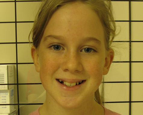
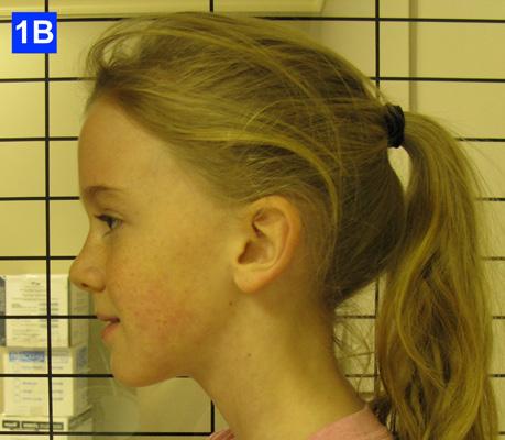
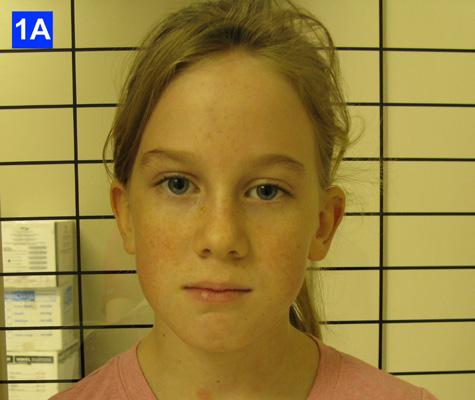
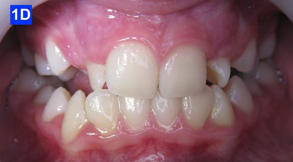
Clinical Macro-esthetic appraisal revealed normal facial symmetry, slightly longer lower face height and straight profile. The patient’s upper (-0.9 mm) and lower (0.2 mm) lips were concave in relation to the “S” line (Steiner) and they were competent (Figure 1-A, B, C).
8
All Patient Photos Used With Permission
Figure 1A: Pre-treatment, frontal view Figure 1B: Pre-treatment, lateral view Figure 1C: Pre-treatment, posed smile
Clinical mini-esthetic appraisal revealed average upper and lower lips and an incongruent smile arc. The patient’s posed smile revealed negative buccal corridors (Fig. 1-C)
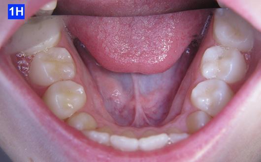
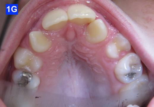
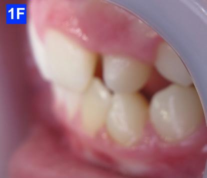
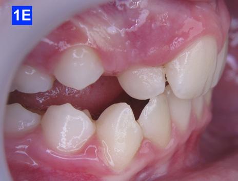
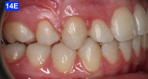
Clinical Micro-esthetic appraisal revealed Angle Class I molar relationship. The arches were narrow, there was crowding, and she had a posterior crossbite. The patient had 2.0 mm overjet and 1.5 mm overbite. There was an anterior cross bite on #12(7) and #22(10), which indicates Class III tendency. The lower airway was very narrow, only 5.0 mm; however, the patient denied SDB symptoms. She did, however, present with symptoms and signs of TMJ dysfunction (Figure 1-D, E, F, G, H,)
Figure 1I: Pre-treatment, posture, frontal view
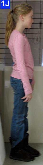

Figure 1J: Pre-treatment, posture, lateral view
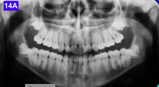
Panoramic radiogram revealed a late mixed dentition with un-erupted wisdom teeth and second molars. A significant finding was noted in that the maxillary cuspids were in transposition with the lateral incisors. There was excellent bone support and no sign of periodontal or peri-apical pathology (Figure 2-A).
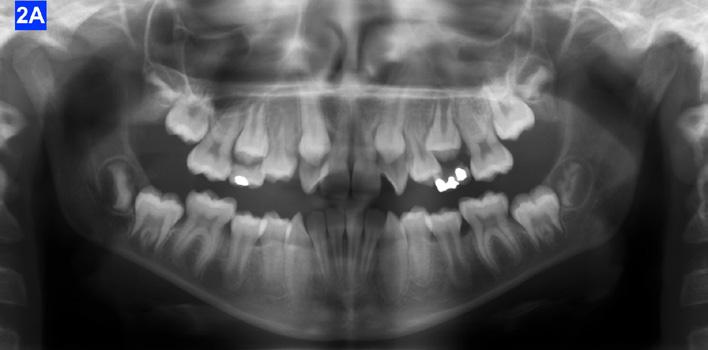
Figure 1D: Pre-treatment, frontal view
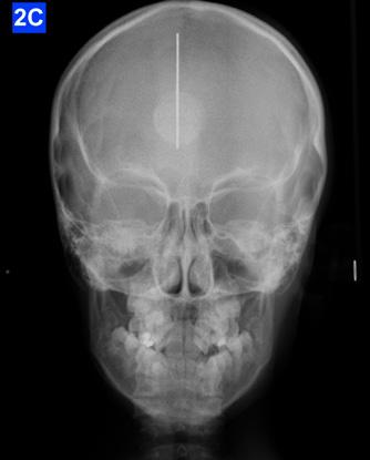
Figure 1E: Pre-treatment, right lateral view
Figure 1F: Pre-treatmrnt, left lateral view
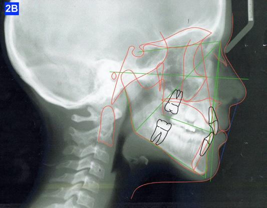
Figure 1G: Pre-treatment, maxilla, occlusal view
Figure 1H: Pre-treatment, mandible, occlusal view
Clinical nano-esthetic appraisal revealed no signs of erosion, abfraction, attrition and abrasion. Periodontal health was good, and the patient was devoid of tooth decay. However, there were amalgam restorations on deciduous molars, ready to exfoliate. Maxillary lateral incisors were narrow.
Clinical appraisal of patient’s posture was significant: the frontal view revealed left head tilt and a high left shoulder, while the lateral view revealed the head forward position (Figure 1-I, J).
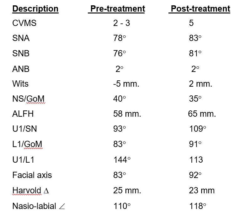
Lateral Cephalometric radiogram revealed a narrow airway in the tonsil area (5.0 mm), retrognathic maxilla and mandible (SNA - 78°, SNB - 76°), retrusive maxillary incisors (U1/SN - 91°), retrusive mandibular incisors (L1/GoM - 83°). She was Class III skeletally as ANB, Wits and the Harvold ∆ were – 2.4°, -5.0 mm and 24.8 mm The patient was hyper-divergent as seen from NS/GoM of40° and a Lower gonial angle of 79.7°. The patient was in CVMS 2 - 3 (Cervical Vertebrae Maturation Stage) (Figure 2-B) and an A-P Radiogram revealed a posterior crossbite (Figure 2-C).
9 9
Figure 2A: Pre-treatment, Panoramic radiogram
Figure 2B: Pre-treatment, lateral Cephalometric radiogram
All Patient Photos Used With Permission
Figure 2C: Pre-treatment, AP Cephalometric radiogram
A Bolton tooth size discrepancy analysis could not be evaluated because the cuspids were not yet erupted. It was noted that the partially erupted maxillary lateral incisors exhibited some signs of microdontia as they appeared to be narrow compared to the upper central incisors.
TMJ appraisal showed the patient had signs and symptoms of TM dysfunction and sensitivity to palpation of several muscles of mastication. This was not a surprise due to the bilateral anterior and posterior crossbite and severe malocclusion.
Diagnosis
The patient exhibited a skeletal Class III pattern, camouflaged with hyper-divergency. There was an anterior and a posterior crossbite along with an Angle Class I molar occlusion. Importantly, the maxillary and mandibular arches were significantly narrowed which contributed to the severe tooth crowding that was evident. In addition, there was 2.0 mm overjet, 1.5 mm overbite and maxillary and mandibular incisors were retrusive. It was further assessed that the maxillary lateral incisors appeared narrow. The airway appeared narrow at the oropharynx with enlarged palatal tonsils and there were signs and symptoms of TM dysfunction. The patient was a habitual mouth breather. A main complicating factor was the bilateral transposition of maxillary lateral incisors with cuspids.
Treatment Plan
The patient was transferred to our office after 12 months of treatment with her previous clinician. She had a maxillary Hyrax, a mandibular Schwarz appliance and a partially bracketed upper arch with .022 x .028 Passive Self-Ligating (PSL) brackets (Carriere – Ortho organizers). The leveling arch wire was a .018 NiTi. The previous clinician proposed; transverse development, SWA and retention. The patient was already referred to an ENT for the evaluation of her airway. The authors explained to the patient and her mother that we may not be able to accommodate the maxillary cuspids and that odontectomy of two bicuspids may be necessary. We would, however, continue with the expansion protocol to its fullest capacity, utilize Straight Wire Appliances and add TADs to assist with translation of the maxillary cuspids. Class III elastics would be necessary and life-time retention of the dentition
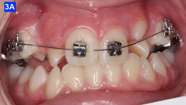
following completion of the treatment. Composite add-ons were considered on maxillary lateral incisors, if required (Figure 3-A, B, C).
Results
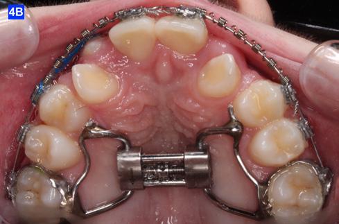
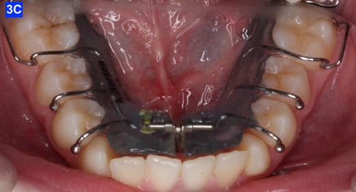
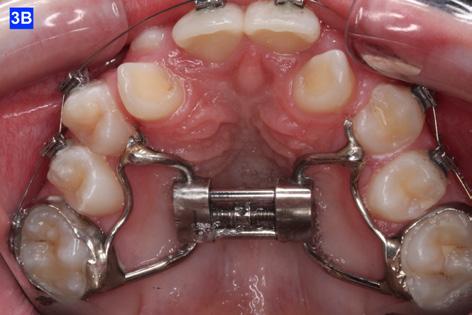
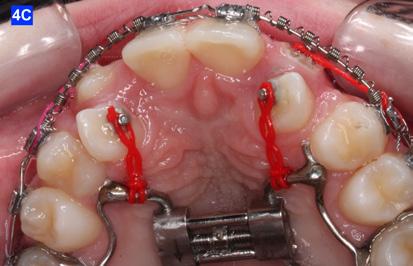
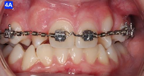
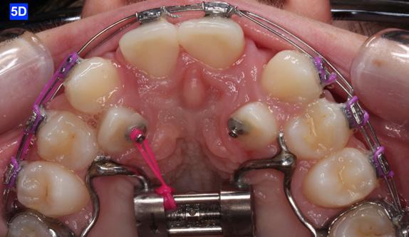
The maxillary cuspids were erupting mesially to the lateral incisors, with very little space to accommodate both teeth without an odontectomy. The expansion was continued (1/4 turn 2x per week), and an attempt was made to create more space for erupting cuspids with an open coil spring (OCS) – between the central incisors and the cuspids (Molar distalization spring, a .010 x .045 - Ortho Organizers). The OCS was measured and cut 4.0 mm longer than the available space. The maxillary arch wire was a .018 SS. An elastomeric chain (EC) was attached from the Hyrax to the lingual button on the lateral incisors. It was necessary to first pull the lateral incisors away from the alveolar process to prevent the break down of the buccal cortical bone around the cuspids (Figure
B, C).
10
4-A,
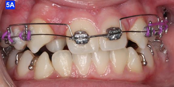
Figure 3A: The patient transferred to our office, frontal view
Figure 3B: The patient transferred to our office, maxilla, occlusal view
Figure 3C: The patient transferred to our office, mandible, occlusal view
Figure 4A: OCS, frontal view Figure 4B: Hyrax, occlusal view Figure 4C: Retraction of maxillary lateral incisors
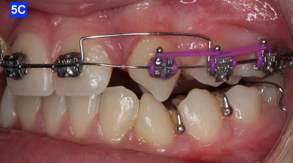
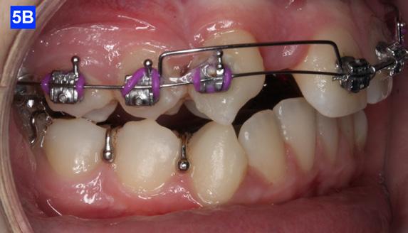
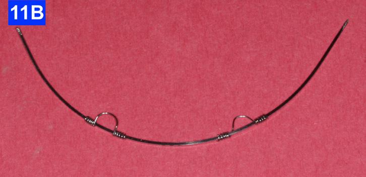
The eruption of maxillary cuspids was expedited with the Adrian “U” bend spring5 where the cardinal arch wire was a .016 SS and the secondary arch wire a .014 NiTi5. Since we were working with the PSL brackets, a combination of larger diameter wires would not allow the latch to close (Figure 5–A, B, C). Also note the progress in retraction of the lateral incisors (Figure 5-D).
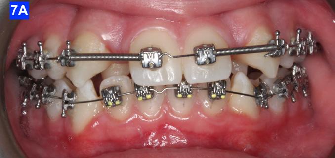
maxillary first bicuspids was the most advantageous way forward. While the parents were contemplating this recommendation, a closed coil spring was added from the maxillary central incisors to the cuspids and attention was directed towards the lower arch. Treatment of the mandible was begun with leveling arch wires (a .014 NiTi followed by a .018 NiTi). In the author’s experience it is often beneficial to delay treatment in the arch that requires less correction if the opposing is significantly more complex. (Figure 7-A).
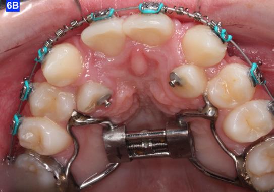
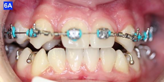
When the maxillary teeth were leveled, we placed a .018 SS arch wire and an OCS to create as much space as possible for the lateral incisors. This technique also allowed us to increase the inclination (torque) of the central incisors as they were too retrusive at the start of the treatment (U1/SN 91°). The maxillary lateral incisors were now completely retracted (Figure 6-A, B).
After 18 months of treatment, there was no more space to further distalize the cuspids as they were already touching the first bicuspids. This left inadequate room for the lateral incisors. The posterior sextants could not be distalized as there was only 1.5 mm overbite, and the pt. was severely hyper-divergent (NS/GoM - 40° vs. Norm of 32° +-3). Therefore, the author felt that extraction of the
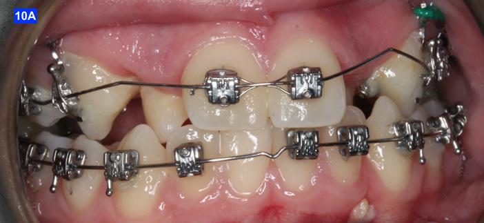
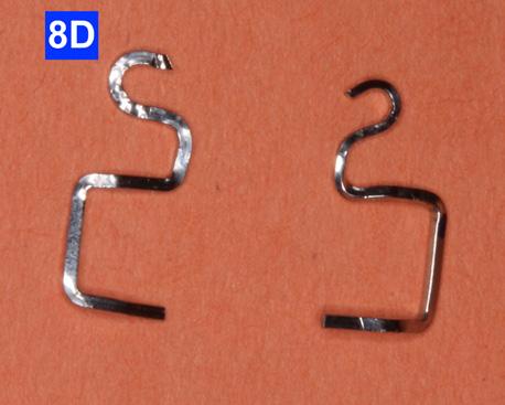
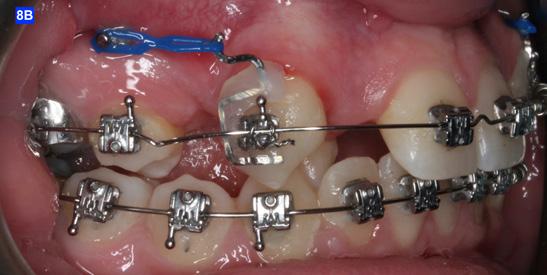
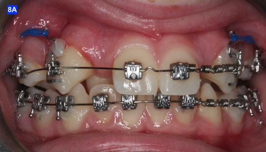
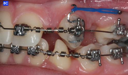
Finally, after 21 months of treatment, the patient and the parents consented to the odontectomy of the maxillary first bicuspids. The informed consent forms for the extractions and placement of TADs were signed by the parent, and all questions were answered. Risks, benefits, alternatives, and the result of no treatment at all were reviewed. Immediately after the odontectomy of #14(5) and #24(12), 1.6 x 8.0 mm AnchorPro (OrthoOrganizers) TADs were placed just mesially to the maxillary second bicuspids.6 In office power arms (a .018 x.025 SS) were fabricated and bonded to the buccal surface of the maxillary cuspids, just above the bracket.7 The purpose of the power arm is to place the applied force as close to the center of resistance of the tooth as possible. In this manner the line of action (power hook to the TAD) is parallel to the occlusal plane. The source of the force is an EC, and it must be replaced at least bi-weekly. Both arches had a .018 SS arch wire. There was a small off-center bend (tip-back, gable bend) “V” pointing occlusally, mesial to the maxillary second bicuspids.8 The purpose of this bend is to keep the roots parallel during the translation of the cuspids. There was a small OCS between #21(9) and #23(11) to shift the maxillary midline to the right. Another OCS was placed between #32(23) and #34(21) to facilitate the alignment of the mandibular left cuspid (Figure 8-A, B, C, D).
11 11
Figure 5A: Adrian “U” bend spring, frontal view
Figure 5B: Adrian “U” bend spring, right lateral view
Figure 5C: Adrian “U” bend spring, left lateral view
Figure 5D: Continuation of retraction, occlusal view
Figure 6A: OCS between the central incisors an the cuspids
Figure 6B: Retraction of the lateral incisors is completed
Figure 7A: Starting treatment on the mandibular arch, frontal view
Figure
Figure
Figure
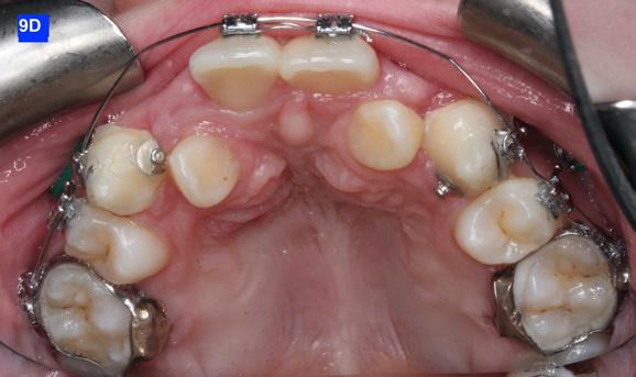
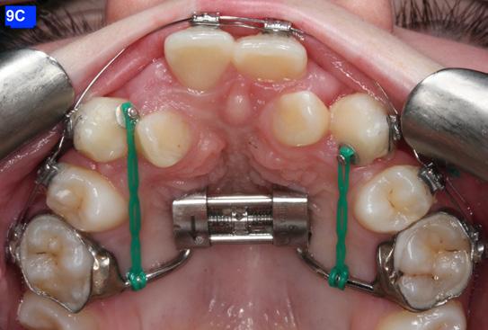
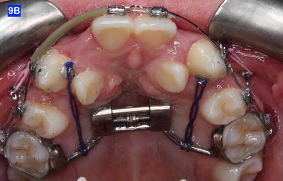
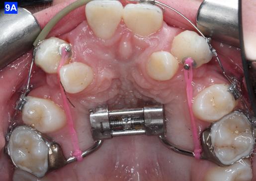
To prevent a disto-lingual moment (rotation) of the maxillary cuspids we attached PC from the lingual button on the cuspids to the framework on the hyrax. The anterior portion of the Hyrax was cut off and the remaining portion served as a TP arch for posterior anchorage. At this point, we were 25 months into treatment (Figure 9-A, B, C, D). The hyrax was removed after 30 months of treatment.
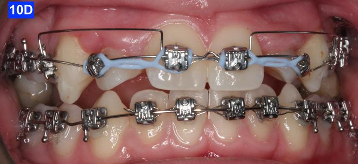
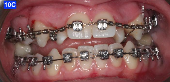
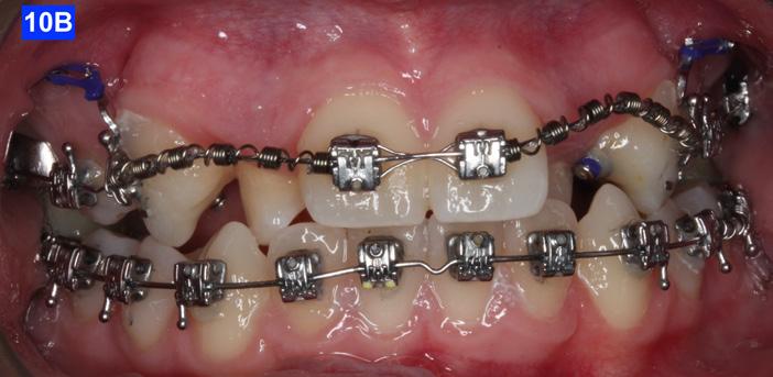
placed between the maxillary central incisors and the cuspids, on a .018 ss arch wire.8 The purpose of this center bend is to move the roots apart. A side effect of this center bend is that the crowns have a tendency to move together. Therefore, an OCS was placed between the maxillary central incisors and the cuspids. (Figure 10 – A, B)
Figure
Figure
After the maxillary cuspids were in contact with the second bicuspids, we had to ascertain that there was adequate width in the inter-radicular space. A center bend - “V” pointing gingivally was
To protract the maxillary lateral incisors into the arch, the bite was opened using composite build-ups on the mandibular first molars. The protraction was started with a .012 ligature tie, and the resiliency of the arch wire created the labial movement of the lateral incisors (Figure 10 - C).
12
Figure 8A: TADs in situ, frontal view
8B: TAD in situ, right lateral view
8C: TAD in situ, left lateral view
8D: Power arms
Figure 9A: Maxilla, occlusal view
9B: Maxilla, occlusal view
9C: Maxilla, occlusal view
Figure 9D: After the removal of the Hyrax, occlusal view
Figure 10A: Center bend “V” pointing gingivally
Figure 10B: OCS between the cuspids and the central incisors
Figure 10C: Composite build-ups on the mandibular first molars
Figure 10D: Adrian “U” bend spring
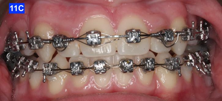
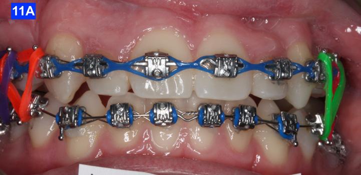
The final labial movement and de-rotation was done by the combined use of an Adrian “U” bend spring and an EC (a .016 SS and a .014 NiTi) (10 – D, E, F). When the maxillary lateral incisors settled in their proper site, the leveling of the maxillary arch was initiated. The progression of the arch wires was a .016 NiTi, a .0.18 NiTi, a .018 SS and the final arch wire, a .019 x .025 SS. There was only a .018 SS arch wire in the mandible. The remaining spaces were closed with a combination of the OCS, EC, and triangular elastics (1/4” – 4.5 oz) (Figure 11-A).
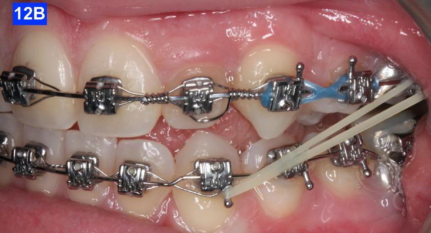
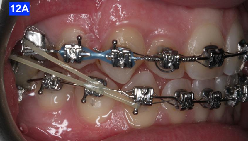
Class III inter-arch elastics (1/4” – 4.5 oz) were introduced to improve the inter-digitation (Figure 12 – A, B).
Count down on retention
After 42 months of treatment, Goodman Torquing springs (Ortho Arch) were crimped on the final arch wire (a. 019 x 025 SS) to create a lingual crown moment (lingual torque) and buccal root moment to upright the displaced maxillary lateral incisors.9 Goodman Torquing springs were left in until the end of the treatment (Figure 11 – B, C).
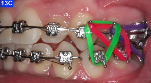
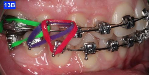
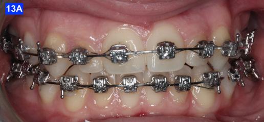
Three months before de-bracketing, while the patient had a .019 x .025 SS arch wire in the maxilla and the mandible, we appointed her for “Count down on retention.” The full arch wire was left in the maxilla, however, in the mandible, it was cut and bent-in, just distally to cuspids. Two triangular elastics were placed per sextant (1/4”– 4.5 oz.) for refinement of the tooth-to-tooth inter-digitation (Figure 13 - A, B, C).8
Figure 13A: Pre-de-bracketing, frontal view
Figure 13B: Pre-de-bracketing, right lateral view
Figure 13C: Pre-de-bracketing, left lateral view
13 13
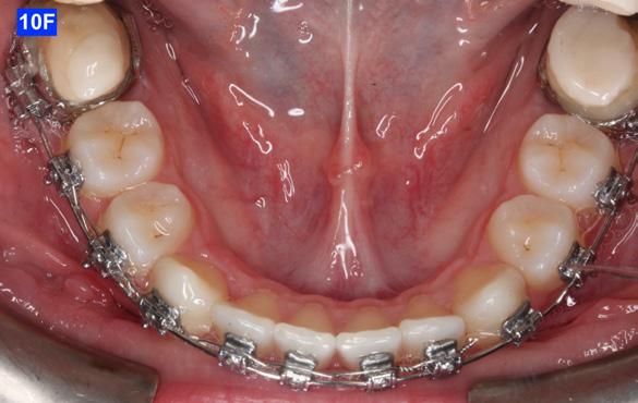
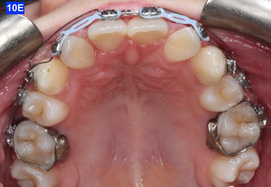
Figure 10E: Maxilla, occlusal view Figure 10F: Mandible, occlusal view
Figure 11A: Frontal view
Figure 12A: Class III elastic, right lateral view
Figure 12B: Class III elastic, left lateral view
Figure 11B: Goodman torquing spring
Figure 11C: Goodman torquing spring in situ
Retention
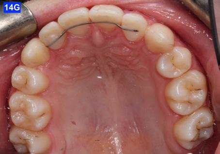
The retainers comprised of a maxillary wrap around QCM retainer, a maxillary bonded retainer, from #12(7) to #22 (10), plus a bonded retainer #43(27) to #33(22), a .028 SS in the mandible. The maxillary bonded retainer was made of a .0215 flexible spiral (braided) wire, and both were bonded with Unitec Bond 1, and Tetric Evo (Ivoclar). The patient was instructed to wear her QCM retainer 24/7 (except sports, brushing her teeth and meals) for 12 months, and after this, only at night.
The bonded maxillary and mandibular retainers are recommended to stay indefinitely.
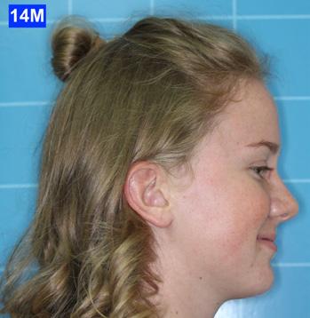
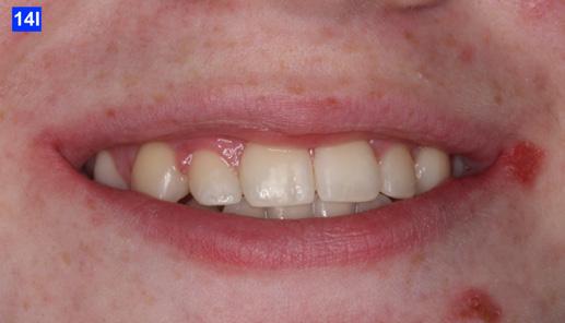
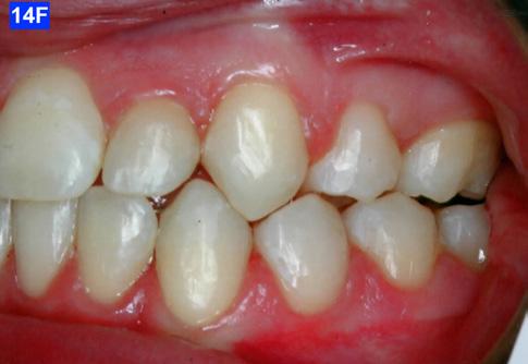
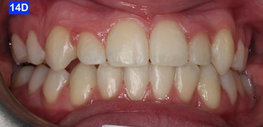
Please view the post-treatment images at the time of insertion of the retainers (Figure 14 - A, B, C. D, E, F, G, H, I, J, K, L, M, N).9
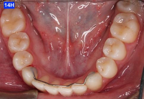
Figure 14H: Post-treatment, mandible, occlusal view
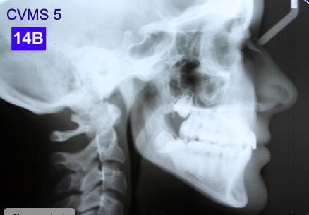
Figure 14I: Post-treatment, posed smile
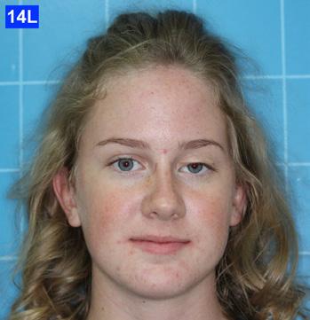
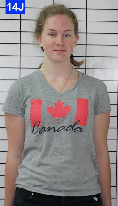
Figure 14A: Post-treatment, panoramic radiogram
Figure 14B: Post-treatment, cephalometric radiogram
Figure 14C: Post-treatment periapical radiograms
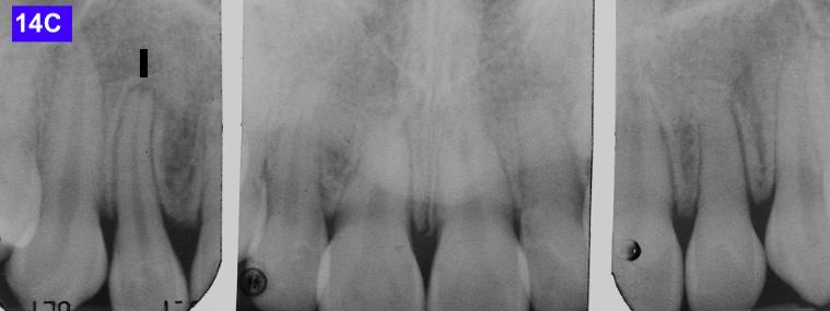
Figure 14D: Post-treatment frontal view
Figure 14E: Post-treatment, right lateral view
Figure 14F: Post-treatment, left lateral view
Figure 14G: Post-treatment, occlusal view
Figure 14J: Post-treatment, posture, frontal view
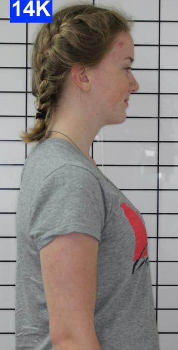
Figure 14K: Post-treatment, posture, lateral view
Figure 14L: Post-treatment, frontal view
Figure 14M: Post-treatment, lateral view
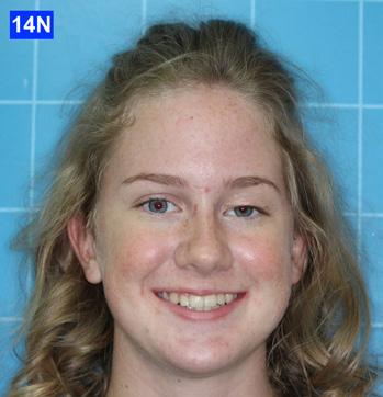
Figure 14N: Post-treatment, posed smile
Discussion
This orthodontic case involved a number of functional and esthetic concerns. Of chief concern were:
• Appearance, negative buccal corridors
• Narrow arches
• Anterior and posterior crossbite
• Crowding
• Transposed maxillary lateral incisors and cuspids
• Enlarged palatal tonsils
14
All Patient Photos Used With Permission
In addition to these problems, the patient presented with habitual mouth breathing and several signs and symptoms of TM dysfunction. The skeletal Class III was superimposed on an Angle Class I molar relation, and she exhibited slight hyperdivergence. The patient’s lips were concave related to the “S” line (Steiner) and competent.
Although the treatment was a lengthy one (60 months), our outcome was favourable. The patient was finished with a skeletal class I, an Angle Class I cuspid and a Class II molar relationship with minimal overjet and overbite. ANB stayed the same however, Wits improved from -5.0 mm to 2.0 mm. ALFH increased by 7.0 mm due to the composite build-ups on the mandibular first molars and elevation of the rest of the mandibular dentition to this height. Also, the growth from CVMS 2 - 3 to CVMS 5 influenced the height of the mandibular alveolar process. The patient’s posture did not change significantly as the frontal view still revealed a slight left head tilt, and the lateral view revealed the head forward position seen previously. We postulate that the lack of greater improvement in posture relates to untreated nasal airway impingement. Olmos writes that nasal airway compromise is thought to exacerbate forward head posture, worsen unfavourable growth patterns (hyperdivergence) and contribute to mouth breathing as the patient is attempting to maintain a better airway.10 It is possible that advancement of the maxilla may have
provided more posture correction given the tendency for these approaches to improve airway volume.10
The position of the anterior teeth was more favourable, U1/SN 93° to 109°, L1/GoM 83° to 91°. The Naso-labial angle became more obtuse from 110° to 118°. The Facial axis (Growth axis –Ricketts) changed to a more ideal value, from 83° to 92°, due to the odontectomy of two maxillary first bicuspids.
The final panoramic radiogram reveals impacted wisdom teeth and distally tipped mandibular second molars that partially erupted. The final periapical radiograms of the maxillary anterior teeth reveal minimal root resorption and acceptable angulation except for #12(7), where the root remained distally oriented.
Concerning the finishing and esthetics, the patient would have benefited from more detailing and refinement but after 60 months of treatment she was exhausted. She expressed great satisfaction with her outcome and we felt the occlusion was acceptable. Therefore, given the understandable treatment fatigue, the patient’s expression of appreciation towards her result, and the functional success, we agreed to end the treatment.
To summarize, the authors presented a case encompassing numerous clinical abnormalities that required a variety of treatment techniques.
The problem list included:
• Bilaterally transposed Maxillary lateral incisors and cuspids
• Camouflaged Class III Skeletal Pattern due to a hyper-divergent growth pattern
• Narrow Maxillary and Mandibular Dental Arches
• Anterior and Posterior Crossbite
• Severe Dental Crowding
• Retrusive Maxillary and Mandibular Incisors
The treatment involved:
• Maxillary and mandibular transverse development
• Straight Wire Appliance
• Retraction of ectopically erupted maxillary lateral incisors
• Odontectomy of maxillary first bicuspids
• Placement of TADs
• Retraction and alignment of the maxillary cuspids
15 15
Table 1: Mid-sagittal (lateral) Cephalometric Analysis
in to the boom
• Protraction and alignment of maxillary lateral incisors
• Finishing the case
• Retention
In conclusion, this case, referred in the midst of treatment to our care, offered us a number of opportunities. Firstly, we were excited to be challenged by such a diverse and significant set of problems. Then, it was motivational to apply a varied and unique set of orthodontic techniques towards those clinical concerns. Thirdly, we were able to watch our plan progress towards achieving a successful result. The greatest opportunity of all, however, was that gleamed from watching this young lady smile when our treatment ended.
References
1. Rasool G, Bibi T, Hassebulah Khan M. Comparison of dento-alveolar heights in relation to vertical facial pattern. JKCD, December 2016, Vol.7, No. 1
2. Johal AS, Battegel JM. Dental Crowding: comparison of three methods of assessment. European Journal of Orthodontics, 19 (1997) 543-551
3. Shapira Y, Kuftinec M.M., Review of Literature and treatment considerations, Angle Orthodontist, 189; 59: 271-276
4. Peck S, Peck L, Classification of maxillary tooth transpositions, American Journal of Orthodontics and Dentofacial Orthopedics, 1995; 107: 505-517
5. Palencar A. J. Virtues of double arch mechanics and “U” bend spring in Straight Wire Appliance, International Journal of Orthodontics, 2017; 28(2); 13 – 17
6. Palencar AJ. Molar distalization with the assistance of Temporary Anchorage Devices. International Journal of Orthodontics, Spring 2015, Vol. 26, No.
7. Giaconti G. Bondable Power arm for self-ligating brackets. Journal of Clinical Orthodontics, August 2008, 675
8. Mulligan TF. Common sense orthodontics in everyday practice. CSM Publishing, 54 – 74
9. Palencar A. J., Case Finishing and Mechanics, Rondeau Seminars Manual
The demand for aligners is growing fast. Offer your patients an effective and affordable option with Tune, an aligner system powered by G&H Orthodontics®

Designed for doctor-led treatment

5% refinement rate and 20% fewer aligner stages
Easy case upload and planning support
Flexible options for every patient and treatment stage
Scan
10. Olmos S., Airway Centered Dentistry: (The A, B, C’s of Treatment for Chronic Face Pain/OSA and Closing Anterior Openbite Without Ortho), Oral Health, March (2017) 44-56

1
Meet your patients’ needs with Tune clear aligners.
the QR code to amplify your growth with a competitive aligner option.
Growing Beautiful Teeth Chapter 3: Beautiful Teeth for Life
Estie Bav is an active member and senior instructor of IAO. She graduated BDSc from the University of Western Australia, and practises in her own private family dental surgery in Melbourne Australia. In November 2018 she published her first book titled “Growing Beautiful Teeth,” primarily targeting parents, grandparents, teachers or any child health carer to look out for early signs of dental growth issues. It informs the unaware the importance and impact of teeth and jaw on other areas of health such as breathing, sleep, posture, and even behaviour.
Currently the dental profession tends to “supervise and wait” for growth issues to become complex and expensive to correct….”
“My concern is that most parents miss out on basic and important dento-facial growth information until too late.”
How my book can be helpful….
It takes time to educate parents on the benefits of treating dental growth issues early and explaining what signs we look for. In writing this book in simple language I hope to bring an awareness to the larger parent community, which will in turn save my dental colleagues chairside time. This book would be a helpful resource for the waiting room, and for introducing the concept to younger colleagues joining your practice.
The book was designed to be a helpful resource for your patient to read, and for introducing the subject to younger dentists and allied health professionals who may not be familiar with the teeth-occlusion-airway-TMJsleep paradigm.
Her message is to get involved with a child’s dentofacial-airway development early.

Growing Beautiful Teeth is available from any major online booksellers, or at

• www.drestiebav.com
• www.growingbeautifulteeth.com
She can be reached at estie@drestiebav.com
17 17 Book Excerpt
We all know that in order to stay alive, we need food to provide nourishments and air to provide oxygen to every cell in our body. We can guess which of the two is of the higher priority by testing to see how long we can do without each one of them.
Just close your nose and mouth and hold your breath for as long as you can. Only a few minutes, right? It is always a priority for our body to get adequate air to stay alive, and not just any air but clean, good quality air that carries the right amount and proportion of oxygen. But air intake or breathing is something we tend to take for granted and not pay too much attention to.
Food and the nourishments just right for our body follow pretty closely behind on the priority ladder although far more attention is being paid to food as evident by the myriad of cookbooks, cooking shows on television and other doco-media, and endless discussions about dietary culture, philosophies and guidelines, and even age-old sayings such as ‘You are what you eat’.
You may be wondering what have nourishments and air got to do with growing beautiful teeth?
A child will need to be breathing well and sleeping well in order to grow well, including the proper development of his/her teeth. This chapter explains why parents should be as focused on how the child is breathing as how the teeth are coming along. Growing beautiful teeth goes hand in hand with developing a wide jaw structure, forward midface and cheeks and a balanced and beautiful face.
When a child’s face is growing in a forward direction and the mandible is also growing forward unhindered, the development of the bony structures provides plenty of space to allow teeth to grow straight and beautiful. This midface growth also provides for a clear nasal airway to facilitate breathing through the nose.
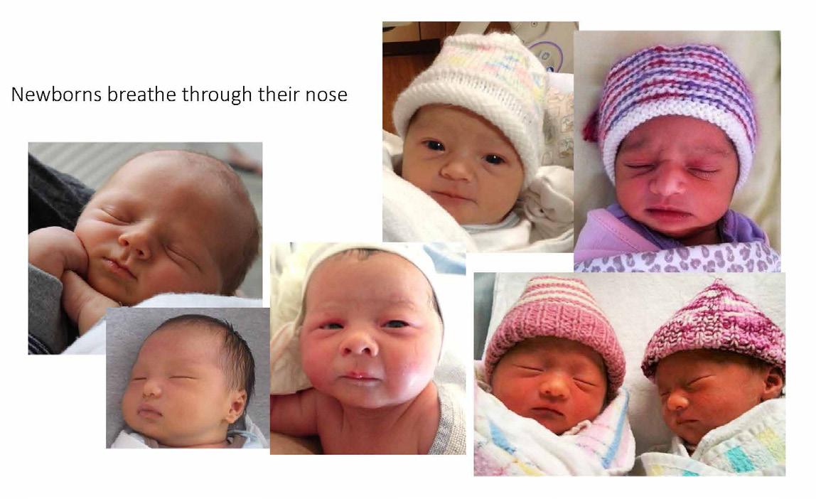
Children should be taught from a very young age and constantly reminded to breathe through the nose. Nature intends that we breathe through our nose and not our mouth. Babies are born nasal-breathers. Look around at newborns and you will observe that they keep their mouth closed and breathe through their nose even when they are sleeping. Yet we observe that at least half of the children around us revert to breathing through their mouth. Why? What happened to cause the change?
Big Rewards for Breathing through the Nose
Inside the nose are structures called turbinates with a special lining that serves to prepare the incoming air. When we breathe in through the nose (and not the
mouth), the air is filtered, warmed and humidified. In other words, the air is conditioned and just right for our body.
Breathing in through the nose also picks up nitric oxide (NO), a gas that is produced in the nose. This gas has antifungal properties and therefore sanitizes the air before it reaches our lungs. Nitric oxide is also essential for the exchange of oxygen at the cellular level.
Therefore, having adequate oxygen intake in our breath isn’t enough as we also need nitric oxide to facilitate the release of the oxygen molecules from the blood for uptake by the cells throughout the body.
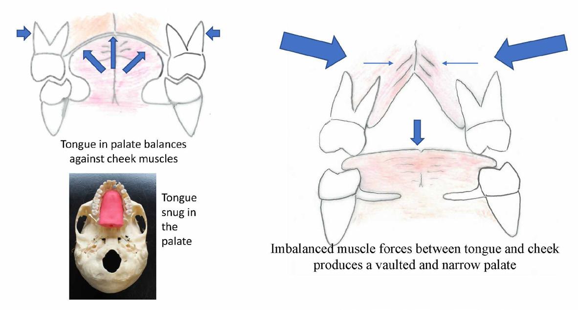
Breathing in and out through the nose also maintains just the right volume of air passing in and out and reduces hyperventilating. To breathe through the nose, the child will need to keep the mouth held closed with lips lightly touching for a natural seal. This keeps the tongue nestled against the palate, which balances against the cheek muscles that press in from without.
Kids who breathe through their mouth tend to grow less attractive, longer and narrower faces and airway/ breathing issues can accumulate through life. A child that always gets a snotty nose and who struggles to breathe through the nose is generally miserable, sad looking and less attractive except, of course, in the eyes of the parents. These kids tend to snore during sleep and parents would report that they are a poor sleeper and wake up suffering from foul breath due to mouth breathing.
Growing beautiful teeth, jaw and face is influenced by correct breathing through the nose – an ideal lifelong habit to adopt.
Tongue in the Palate
By keeping the mouth closed, it becomes easier to breathe through the nose, and this also keeps the tongue naturally held against the palate which is the key to maxilla growth.
18
Figure 10: Natural nasal breathers
Every time we swallow our saliva, the tongue should press into the maxilla. In a growing child, this contact stimulates the palate to grow broad and flat, producing a wide dental arch with ample room for the growing teeth. This also enhances the development of the nasal cavity to give plenty more space for air passage and stimulates midface growth in the forward direction. In other words, proper breathing habit, balanced facial growth and beautifully aligned teeth go hand in hand.
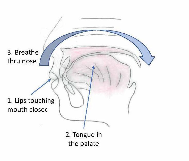
The three must go together: breathe through nose, lips touching, tongue resting against the palate with no deviant habit. Dr Steve Galella, a dental educator from Tennessee, referred to this as the ‘Big 3’. It is so simple. When adopted at a young age, the Big 3 becomes natural and easy, and will stay with the child for amazing health benefits.
usually also have a deviated nasal septum and a habit of breathing through their mouth. Constant mouth opening also grows a longer and narrower face with restricted pharyngeal airway.
What Triggers Mouth Breathing?
We asked earlier: what may be triggering a child to breathe through an open mouth? The most obvious answer is a blocked nose and/or difficulty in breathing. Could it be an allergen or pollution in our air and environment that is causing an overreaction or hypersensitivity response leading to a congested nose?
We are observing an increased prevalence of food allergies and asthma in children in the modern world. In parallel, there seems to be a similar increase in prevalence of teeth growing crooked.
A child who finds it hard to breathe through the nose will resort to mouth breathing. As explained earlier, this results in the steepening of the palate which encroaches into the nasal cavity that lies just above. People with a deep palate and crowded teeth
Tonsils and Adenoids
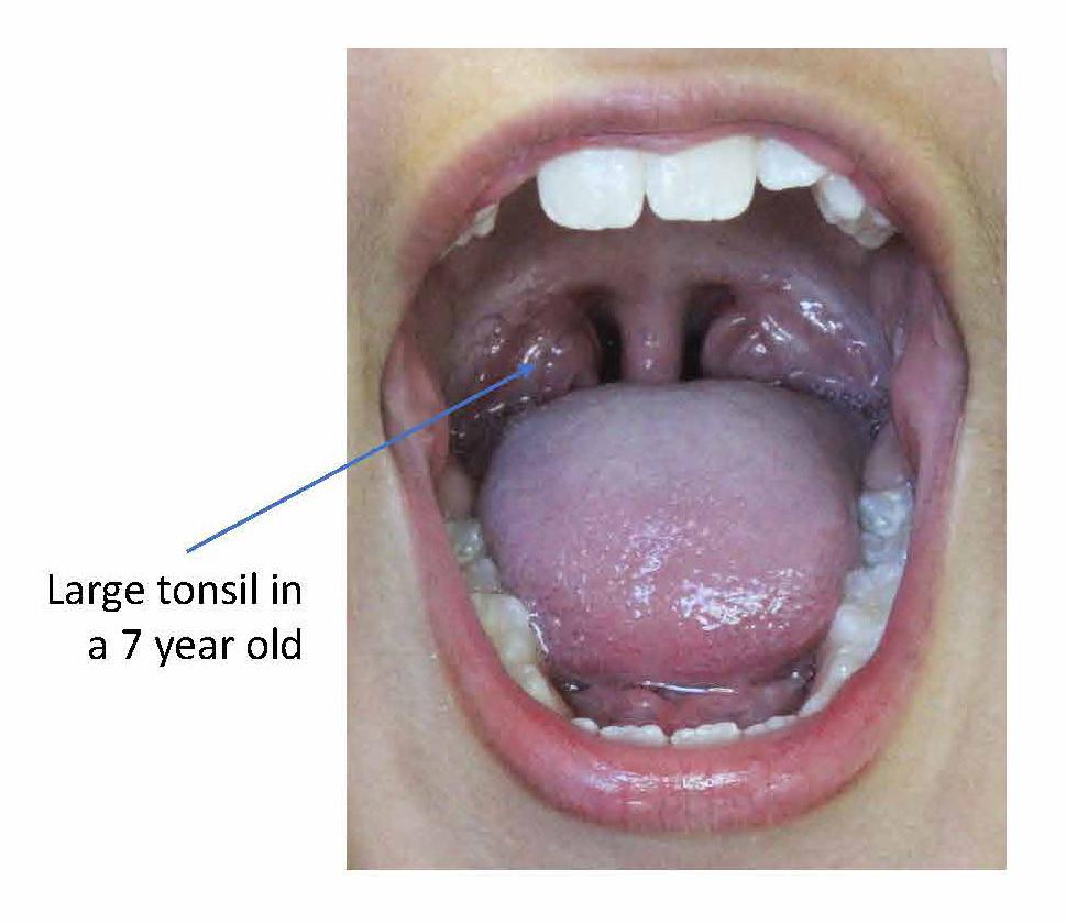
Children with breathing issues and who do not breathe through the nose often have enlarged tonsils, or adenoids. It seems to be a vicious cycle: the mouthbreathing pattern introduces unfiltered air into the throat that leads to irritation and infection of these tonsils and adenoids and, when these inflamed lymphoid tissues swell up, they further induce blockage and breathing difficulties, so the child feels the urge to continue to breathe through their mouth. Unlike inside the nose, there is no filter in the mouth to clean the inhaled air.
Parents who bring in their child to see me with dental growth concerns often add that the child also has breathing difficulties such as a blocked nose, runny nose, frequent coughs and colds. These kids may be on medications for asthma. Many of these children also have a history of having grommets or tubes placed inside their ears for improved drainage.
These medical symptoms are red flags telling us that the child’s palate, upper jaw and mid face may not be developing well, and the child should be checked for the Big 3. It is essential to see the dentist early for dentofacial growth assessment. The child’s teeth and jaw have a close developmental, physical and functional connection to their ear and nose and breathing.
It is quite easy for the parents or dentist to have a quick check at the child’s tonsils. Ask the child to stick their tongue out and say, ‘Ahh.’ The throat can be given a cursory inspection. If parents detect or are concerned that the passage appears to be closed in, it is time to ask for a referral to an ENT doctor.
19 19
Figure 11: The Big 3.
Figure 12: Lowered tongue causes narrow palate.
On that note, I add that in my experience not all ENT surgeons necessarily follow the paradigm of mouth, jaw, teeth, nose breathing, sleep and growth. Some doctors may hold the view that tonsils and adenoids will disappear with time. The doctor may only want to prescribe drugs such as antibiotics to treat the symptoms and not delve deeper into the cause of the problems or the connection with the child’s disrupted sleep and dentofacial growth.
Searching for the right ENT surgeon to work with is important. Obviously, parents, physicians and dentists need to be on the same page with regards to this paradigm of health care. In recent years, I have had the good fortune of hearing many excellent paediatric sleep physicians and paediatric ENT surgeons who educate other professionals such as myself and share their views on this very interesting paradigm. They may come from different perspectives; however, not surprisingly, they all say the same thing, that nasal breathing, airway, sleep, jaw structure and tongue are related.
Breathing Retraining: The Buteyko Method
It would seem an impossible task to ask a child to not breathe through the mouth when their nose is blocked. So how can we encourage nasal breathing in this situation? It seems like a paradox, but keeping the mouth closed will help to relieve the blocked nose. This is where the principle of the Buteyko Method of breathing retraining comes in.
Konstantin P. Buteyko was a Russian doctor and a professor in physiology. In the early 1950s, he discovered that normalizing breathing from a hyperventilating state can reverse asthma. He founded the principle that
hyperventilation or over-breathing is damaging for health.1
The Buteyko Method trains one to not give in to the slightest urge to gasp for air, by calming and slowing down one’s breathing and to always breathe only through the nose. Reducing the urge to gasp conserves the level of carbon dioxide in the lung, stops hyperventilating and effectively helps to unblock the nose.
Whilst Professor K Buteyko’s Method originally served to treat asthma without using drugs, it turned out that the Method can complement treatment for dentofacial growth by strengthening the Big 3. Dentists know that the Big 3 are essential factors for developing the maxilla and the midface, and supporting good oropharyngeal airway; however, it is not so simple as asking a patient to just go and start breathing through their nose, voila! Not even for a most determined adult young or old, let alone a young child (who has a busy mum and dad).
I see the Method as a breathing boot camp to help break and remove bad breathing habits and effectively replace it with good, lifelong habits of calm and quiet breathing through the nose.
Qualified Buteyko practitioners can be found at the Buteyko Institute of Breathing and Health (BIBH) website. I like to work with such breathing retraining specialists, allowing them to provide individual programs for my patients which will enhance their dentofacial treatment outcome.
I recommend parents to do some research and understand the amazing benefits of breathing retraining. There are many excellent online articles and useful exercises on YouTube available for free.2,3,4,5
Breathing retraining can ideally start from the age of about 7–8 years, and even earlier for some children. In my practice, I have observed that following a course of breathing retraining such as the Buteyko Method, the child definitely becomes more aware of how they breathe and they quite effectively change their breathing habit from using their mouth to their nose.
One is never too young or too old to learn nasal breathing. It’s a matter of use it or lose it with the nose.
Forward Head Posture
Mouth breathing requires a constant open-mouth posture, and this directs lower jaw growth in a down
20
Figure 13: Large tonsils.
and backward direction. A backward growing mandible further keeps the tongue closer to the throat and adds to the narrowing of the oropharynx. To compensate and regain some airway, there will be a slight head tilt-back posture at the neck.
The next compensation is by the shoulder and upper torso carrying the head down and forward to level the eyes. As the child grows, these habit and postures continue to foster growing narrower and longer faces, and also a forward head posture.
It is a common observation that forward head carriage is accompanied by a backward lower jaw and vice versa. So, wide maxilla, forward dentofacial growth and the Big 3 equals good posture for the body.
Facial Beauty
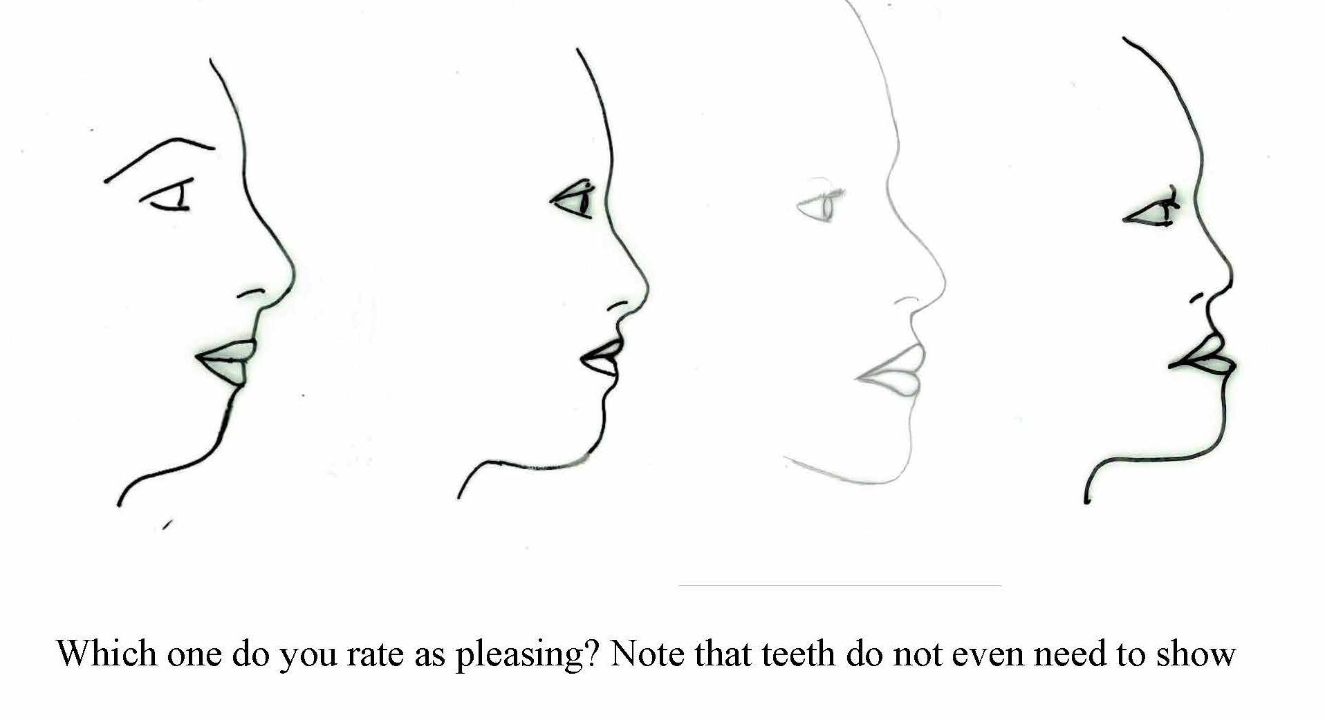
Observe around you and you will see that beautiful faces with a balanced profile have the nose, lips and chin well aligned (forward). They look attractive regardless of teeth alignment.
A person with a balanced facial profile, who is breathing naturally and effortlessly through the nose will exude a universal image of good health and facial beauty regardless of their ethnicity. By contrast, if the lower jaw and chin is not forward enough, the face will look convex and appear less attractive even if their teeth may be straight. When the midface is flat or even concave, it will detract from a beautiful face
When the upper and the lower jaws are balanced and are forward, approaching a plumb line with the nose, we see an attractive facial profile.
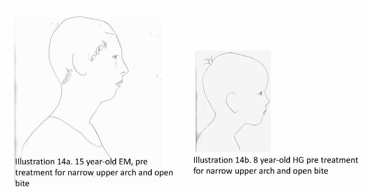
By contrast, when the upper and lower dental arches do not match up, a narrower upper jaw can prevent the lower jaw from relating more forward. The result can be a rather convex facial profile, with a chinless appearance as will be illustrated by the shoe diagram. The nose can
appear too big. We should not be blaming the nose but blaming the jaws that are too far back.
Think of nice cheek bones in a beautiful face. We do want the midface to develop forward so the lower jaw can develop forward as well to balance the upper part of the face.
Think of the nice strong jaws belonging to famous and good-looking people such as Angelina Jolie, Audrey Hepburn, Brad Pitt, Chris Hemsworth, or David Beckham and we can appreciate how the jawline enhances the perception of beauty. A forward jaw reduces the risk of the tongue blocking the airway during sleep.
We need to teach the correct habit of breathing through the nose, good tongue and jaw muscle posture and patterns through lips closure and proper chewing. This holistic and natural way to guide teeth, jaw and facial growth in the very young child will bring far reaching health rewards.
References
1 S Yakovleva, KP Buteyko & AE Novozhilov, Breathe to Heal: Break Free from Asthma, USA, BreathingCenter, 2016
2 Dr Rosalba Courtney at https://www.rosalbacourtney.com/
3 Buteyko Clinic at https://buteykoclinic.com/
4 Buteyko Clinic YouTube channel at https://www.youtube.com/user/ buteykoclinic/featured
5 Buteyko Health & Breathing (Paul O’Connell) at https://buteykoairways. com.au/
21 21
Figure 14: Forward head posture
Figure 15: Facial profiles, convex to concave
Pre and Post T-Scan Occlusal Analysis of an Orthodontically Treated Class II Patient with no Canine Guidance – A Case Report
By Svitlana Koval, BDS, MDS, DMD, and Robert B. Kerstein, DMDb

Abstract
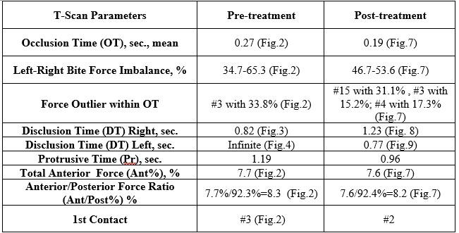
An orthodontically treated Class II patient was measured with T-Scan 10 digital occlusal analysis before and after treatment. Orthodontic treatment improved the right side - left side force side force percentage imbalance, and decreased the occlusion time. Although the pattern of initial contacts remained similar, the disclusion times did not improve significantly. The orthodontic treatment improved some functional characteristics of the occlusion, but not all, leaving in place both working and non-working side interferences, with resulting increased disclusion times.
Key Words: T-Scan 10, Disclusion Time, A/P % Ratio, Canine Guidance, Anterior Overbite
Introduction
Orthodontic treatment serves several goals, including improving the smile aesthetics, the correction of the severely malposed teeth to alleviate periodontal problems, and to alter the functional characteristics of the occlusion. While some variables of the Objective Grading System score1 (OGS, like the alignment) serve the primary purpose of satisfying the aesthetic requirement, others like the marginal ridge heights, the buccolingual inclination, the occlusal contacts, and the occlusal relationships are also considered direct and indirect determinants of a properly functioning occlusion. Nevertheless, even in the presence of clear determinants of an ideal orthodontic treatment outcome, orthodontically treated cases have been shown to exhibit compromised functional occlusion.2
There exist a number of researched, functional occlusal parameters that can be measured with T-Scan 10 digital occlusal analysis (Tekscan Inc. Norwood MA, USA). These include the occlusion time (OT), the disclusion time (DT) in protrusive and laterotrusive movements, and the right side-left side occlusal force

22
Featured*
*This article has been peer reviewed
Dr. Svitlana Koval
DMD (Boston University Goldman • School of Dental Medicine), MSc Ortho (Odessa State Medical University), BDS (Odessa State Medical University) y
Dr. Robert B. Kerstein
DMD and Prosthodontic Certificate (Tufts University of Dental years, 38 Medicine). Over the past he has published many original research studies using all versions of the T Scan. He is a leading authority and researcher in the field .of Computerized Occlusal Analysis
percent imbalance. Interestingly, there was a significant correlation found between reduced OT durations and improved OGS scores.2
The T-Scan 10 digital occlusal analysis has been proven to be an accurate and rapid diagnostic tool in measuring occlusal relationships in different areas of dentistry, including Orthodontics.2,3,4,5 The disclusion time reduction (DTR) enameloplasty significantly improved average chewing patterns, according to Kerstein and Radke.6 Learetta confirmed that both T-Scan and EMG recordings were suitable for detecting interferences, and improving chewing characteristics in patients with TMDs.7 Other studies have shown an association between the occlusal force distribution, the differing relative occlusal forces, and the right side-left side force percent imbalance, and the presence of TMD symptoms.8,9 Lastly, a study found an association between high occlusal forces and periodontal disease indicators, such as bleeding on probing and pocket depths.10
Although there is no clinical agreement on whether canine guidance should be an occlusal scheme of choice, although a significant number of researchers confirm that it is beneficial.11,12,13 Whether there is solely a canine or an anterior group guidance that is responsible for discluding posterior teeth, short disclusion time has been shown to be a major determinant of a physiologic, low muscle firing occlusion.6,14,15,16,17,18
Functional occlusal parameters, such as the guidance scheme (canine, anterior, group function) or the existence of working and non-working side interferences, are routinely visually assessed with conventional occlusal indicators (articulating paper, articulating foil, occlusal wax, impression silicone), which give only end-point information about the surface area of occlusal contacts. The dynamics of occlusal function are impossible to evaluate with these static indicators because they do not quantify anything occlusal.
Orthodontically treated patients measured with T-Scan have shown increased disclusion times in lateral excursive movements, the presence of working and non-working side interferences, excessive posterior closure contact forces, and poor right side - left side occlusal force percent balance.19,20 As such, the aim of this manuscript was to analyze with the T-Scan 10, the functional occlusal characteristics of an orthodontically treated patient, to determine the occlusal characteristics that require more attention during the finishing stages, and to hypothesize the possible causes of their occurrence.
Case Report
A 32-year-old female presented with facial asymmetry, with her chin shifted to the left, a retrognathic mandibular profile, a horizontal growth pattern, Class I molar and canine relationships on the right side, Class II molar and canine relationships on the left side, and upper and lower moderate anterior crowding.
Pre-treatment T-Scan 10 recordings were made to evaluate the pre-treatment occlusion using a standard T-Scan diagnostic protocol that involves five specific recordings (pre-treatment records, Figures 1-4).
• Centric occlusion
• Multi-bite,
• Right lateral excursion
• Left lateral excursion
• Protrusive excursion
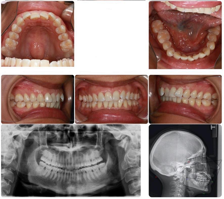
presented with upper and lower moderate-to-severe crowding, along with molar Class III and canine Class I right side alignment, molar and canine Class II left side alignment, and mild anterior overbite. The lateral cephalometric tracing before treatment determined an ANB angle = 4.2 degrees, NL-NSL =10.0 degrees, and ML-NSL= 20.0 degrees, which corresponds to a skeletal Class II with clockwise maxillary base rotation, and a horizontal growth type.
23 23
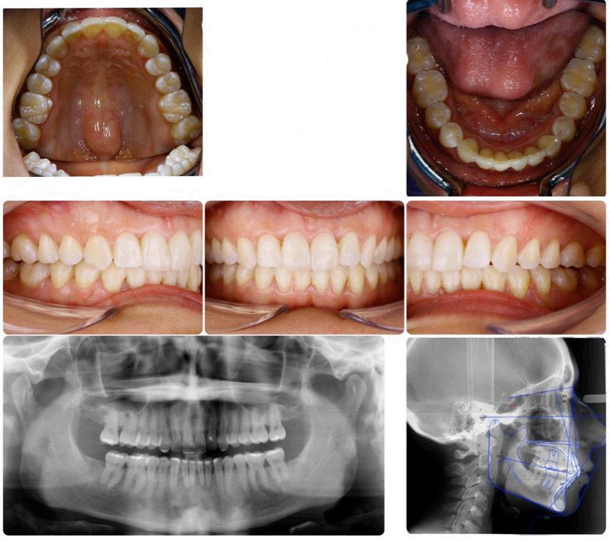
Figure 1: Intraoral photographs, and panoramic and lateral cephalometric radiographs before treatment. The patient
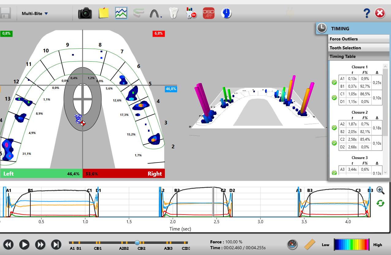
Figure 2: A Multi-bite recording before treatment illustrating an Anterior/Posterior Force % ratio (A/P ratio) = 8.3%/92.7%.
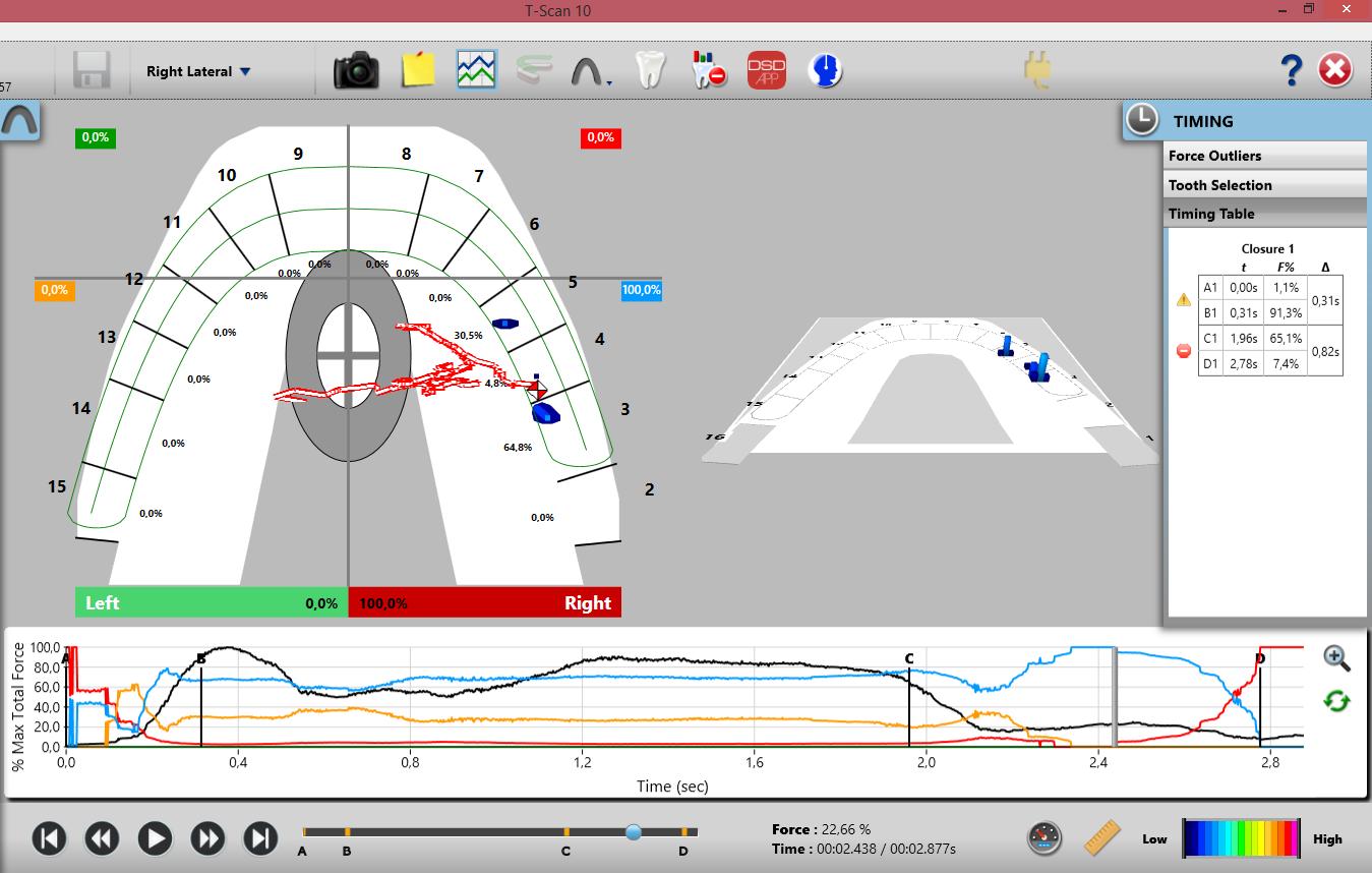
Figure 3: A right lateral excursion before TX: 0.82 sec with eventual canine guidance. The Blue Line extending from Point C to D indicates the prevalence of a working side group function guidance pattern that precedes the anterior disclusion at D. Throughout the excursion teeth #s 3 and 5 control the right working movement until eventually the anterior right quadrant controls the late excursion (when the red anterior quadrant line reaches 100% force at 2.8 seconds).
patient repeatedly closed into complete intercuspation three consecutive times, holding each MIP for 2-3 seconds, and then opening out of intercuspation. During excursive recordings, the patient closed into complete intercuspation, held it for 2-3 seconds, and then moved their mandible to the right, or to the left, or protrusively, sliding over their anterior guiding surfaces. An excursive recording was complete when the patient reached their most lateral edge-to-edge incisal position.
The occlusion time (OT) is the elapsed time in seconds, measured from the first tooth contact until static intercuspation is achieved, as a patient closes all their teeth together from completely open (no tooth contact) until complete intercuspation. Static intercuspation21 always precedes maximum intercuspation force levels (MIP), and is detected in the T-Scan Force vs. Time graph at or near to 90% of maximum force. The occlusion time describes the degree of bilateral timesimultaneity present in a patient’s occlusion, and is ideal when the OT < 0.2 seconds in duration.21
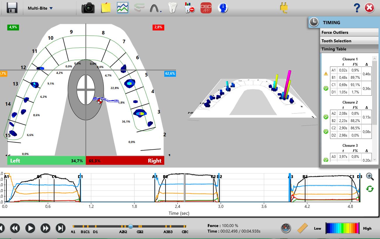
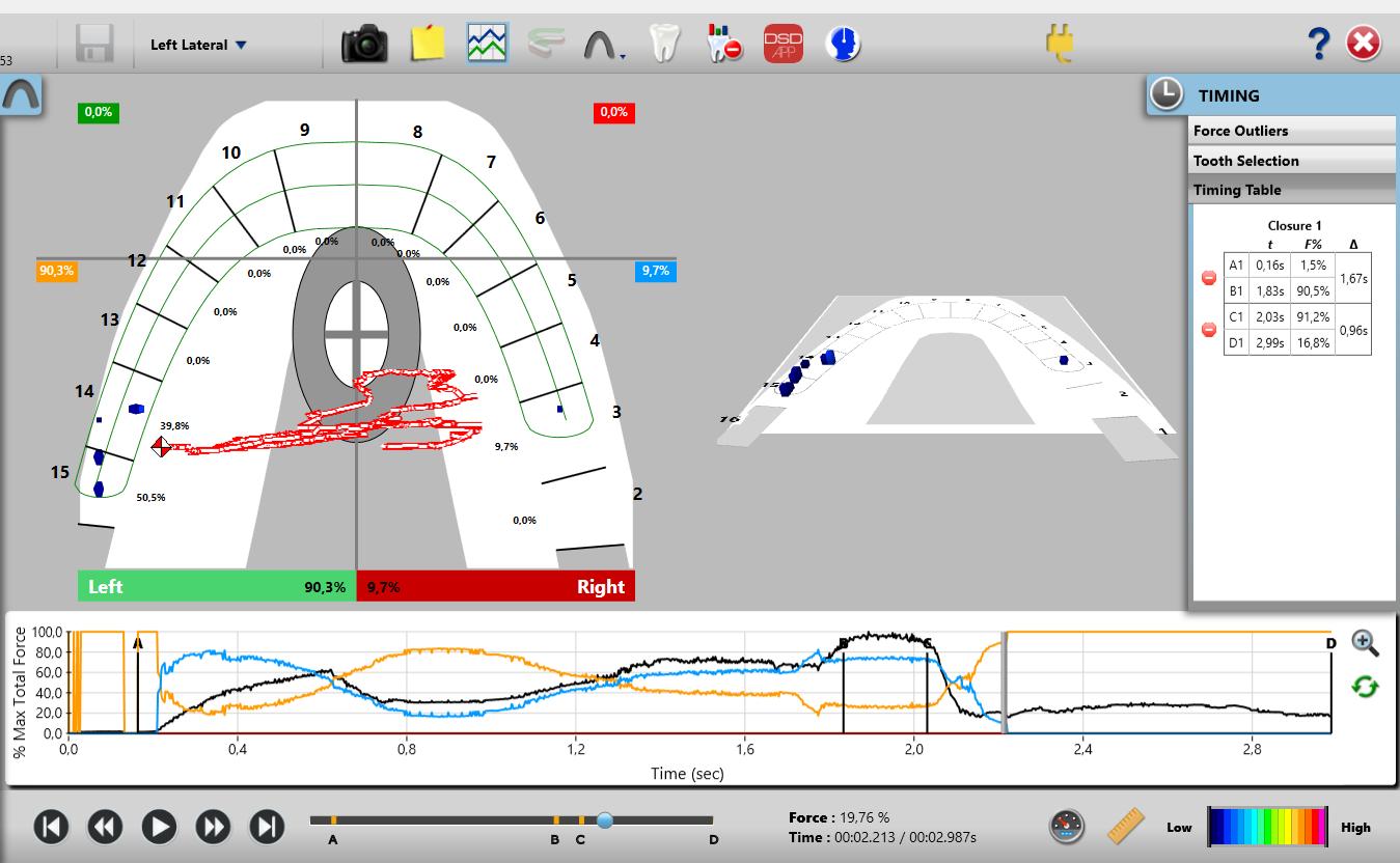
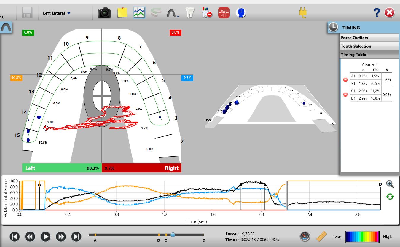
Figure 4: The left lateral excursion before Tx. Although the excursive recording ends with a DT = 0.96 sec., the DT is actually infinite, because the orange posterior left quadrant is never replaced by the anterior left quadrant. Guidance control is on teeth #s14 and 15 with working-side interferences, along with a non-working side interference on tooth #3.
T-Scan recordings were made with the patient seated upright in the dental chair. Calibration of the HD Novus recording sensor (Tekscan Inc., Norwood, MA, USA) was done prior to the recording procedure, by setting the recording Sensitivity to limit the amount of pink sensels to 3. This matched the sensor response to the patient’s occlusal strength.
The Centric Occlusion recording involved the patient occluding into the sensor to make a single complete closure into maximum intercuspation (MIP), which was held for 2-3 seconds, and then the patient opened out of occlusal contact. For the multi-bite recording, the
The disclusion time (DT) is the elapsed time in seconds, measured from the beginning of an excursive movement made in one direction (right, left, or forwards), beginning with all teeth in complete intercuspation through until only canines and/or incisors are in contact.22 The disclusion time describes the capability of a patient’s Anterior Guidance mechanism to functionally separate posterior teeth. Both the occlusion time and the disclusion time are occlusal function parameters that cannot be detected with articulating paper markings, wax or silicone imprints, visual inspection of patient movements, or with intraoral scanners.
The Anterior Force Percentage (Ant %) is the sum of the left anterior and right Anterior quadrant relative forces, as seen in a four-quadrant view of the 2D ForceView T-Scan window. The Anterior Forces are calculated anterior to a horizontal line dividing the 2D ForceView into four quadrants at the distal of the canine teeth and mesial to the premolar teeth.14,15,16,21 This creates a left anterior, a right anterior, and left and right posterior quadrants within the 2D ForceView window.
The Anterior-Posterior Force % Ratio (A/P ratio) is the ratio of the % force sum of the anterior quadrant compared to the % force sum of the posterior quadrants. This characteristic has been shown to be of a particular interest when analyzing the outcome of orthodontic treatment.19
24
The initial contact is the first recorded contact when teeth begin to intercuspate. The initial contact is determined from a multi-bite recording, as this repeating closure data allows for a clear view of the 1st contact’s repeating occurrence.
The overall treatment time for this patient was 18 months using traditional straight-wire technique, Victory series brackets (3M Unitek, Monrovia, USA), 0.022 x 0.028’’ slot, and an MBT prescription (the bracket prescription provided dimensional positioning data for the orthodontic wire, being the torque, the angulation, and the offset).
The initial crowding was associated with some physiologic contact area attrition, which exposed visible black triangle areas from a lack of gingival papillae after initial alignment. Mesial and distal edges of the upper and lower anterior teeth were reshaped to increase the length of their contact zones, which achieved a closer allocation of the contact areas to the crestal bone.23
The Class II correction was achieved with Class II elastics (3/16”, 4 oz., Bill, 3M Unitek, Monrovia, USA). Initially, these elastics caused extrusion of the anchoring teeth, with only four points of contact registered on the T-Scan 2D and 3D ForceView arch models.4 Subsequent mechanics achieved better contact distribution along the rest of the dental arches.
A T-Scan 10 occlusal analysis was repeated after the orthodontic treatment to compare to the pretreatment condition (Table I) (post-treatment records, Figures 6-9).
Table 1: Pre and post-treatment T-Scan data indicating improvement in the OT and the left side-right side force % imbalance. However, the closure force outlier contacts within the OT remained similar (#s 3, 4, 15). Treatment shifted the first contact #3 to #2 (more distally). The Total Anterior Force % and the Ant/Post % ratio remain unchanged. The left and protrusive Disclusion Times were partially improved, while the right DT worsened.
Figure
left lateral excursion before
Although the excursive recording ends with a DT = 0.96 sec., the DT is actually infinite, because the orange posterior left quadrant is never replaced by the anterior left quadrant. Guidance control is on teeth #s14 and 15 with working-side interferences, along with a non-working side interference on tooth #3.
25 25
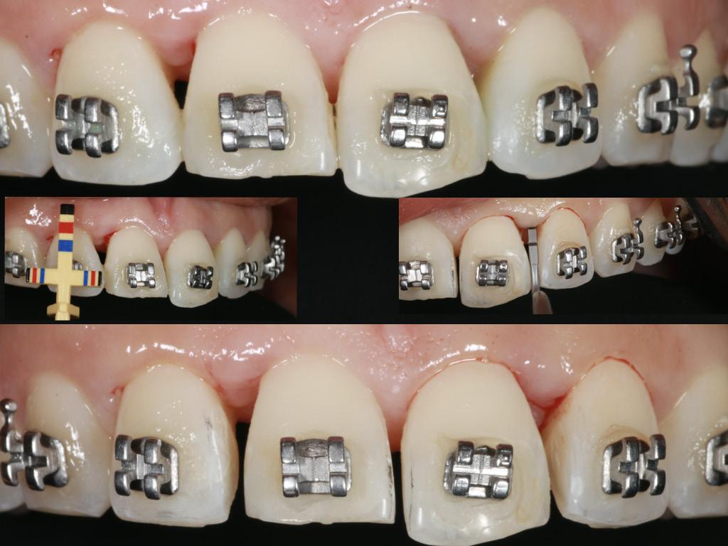
Figure 5: Interproximal reduction with crown remodeling for papilla preservation. The bracket on the tooth #9 was intentionally rotated distally to improve the root angulation.
Figure 6: The post treatment intraoral photographs, the panoramic radiograph, and the lateral cephalometric radiograph with tracing. An increased ANB angle resulted from changing lower incisor root position with counterclockwise mandibular rotation. The decreased ML-NSL angle resulted from leveling the occlusal plane.
4: The
Tx.
right side -left side bite force imbalance now = 53.6 % right -46.4% left, with 31.1% force on #15, 15.2% on tooth #3, and an Anterior/Posterior Force % ratio after treatment (A/P ratio) = 8.2%/91.8%.
divided in quadrants,
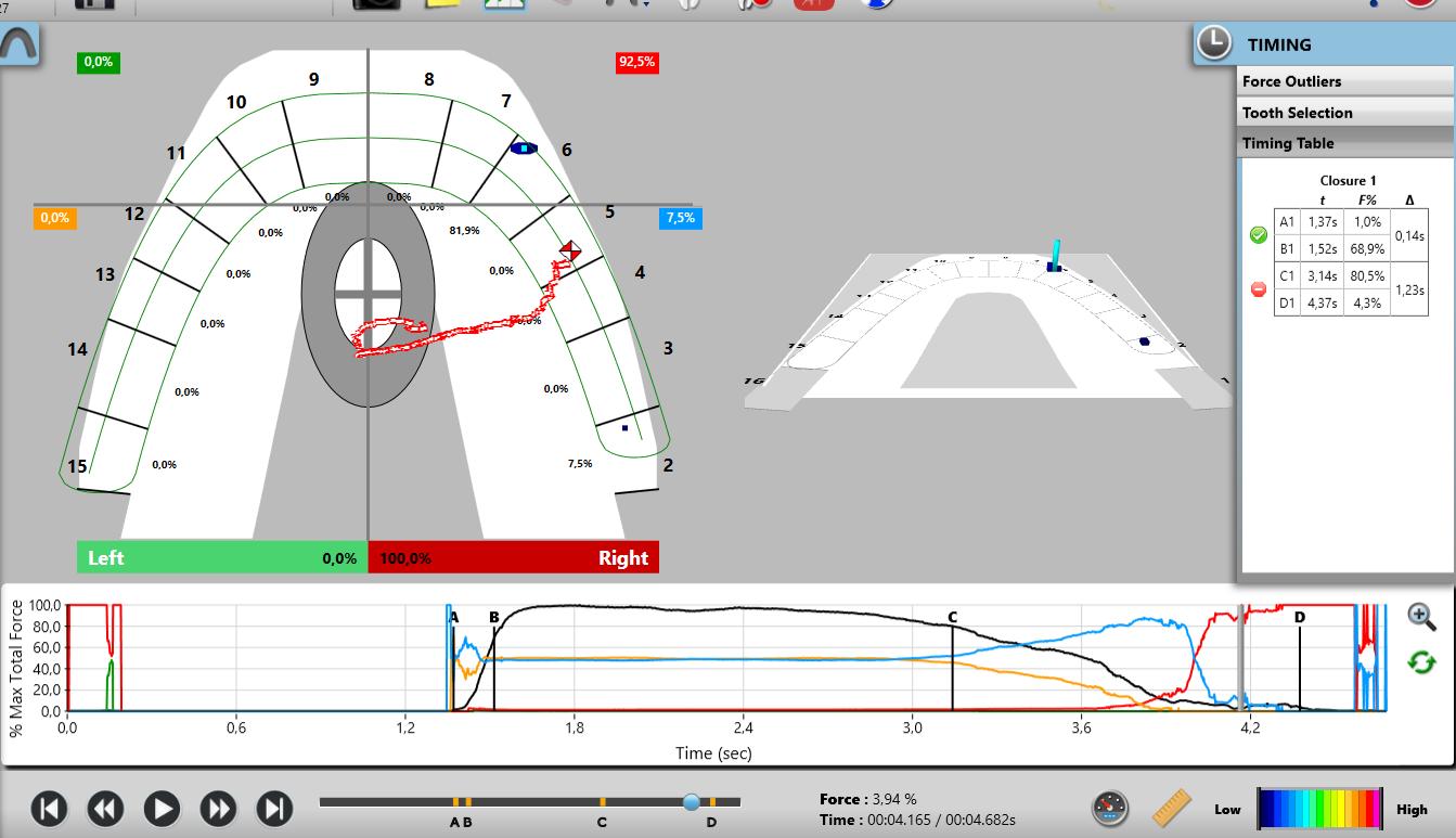
Figure 8: The right lateral excursion after treatment shows very late canine-guided disclusion after a prominent group function controls most of the early excursion (blue line precedes red line reaching 100%). The DT = 1.23 sec, which is significantly higher than the normal limits for excursive movements (0.4 sec per excursion). The Blue Line dominates the excursion after Line C (at 3.2-4.0 seconds of the recording), and it takes another 0.43 seconds to fully eliminate the working side interference on #2 to achieve a
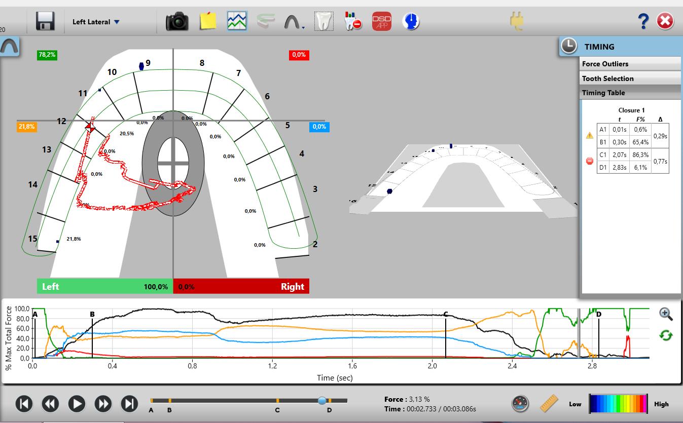
Figure 9: The left lateral excursion after Tx. There is 0.77 seconds of working side group function (Orange line to the right of the C Line) that precedes the canine guidance (when the Green anterior left quadrant line reaches the top of the Force vs. Time graph). The trajectory of the Center of Force trajectory(COF) in closure into MIP moves from the left upper canine towards the center of the arch. When the excursion begins, the COF moves first into the left posterior teeth because of the working side interferences (seen by the Orange quadrant line) that precede complete left canine disclusion, and then moves north towards toot #11. The Disclusion Time is 0.77 sec, which is above the physiologic level of 0.4 secs per excursion.
The treatment improved the Occlusion Time durations (down from 0.27 secs. to 0.19 secs.), and the left side-right side force % imbalance (from 34.7% left - 65.3% right to more equal at 46.7% left53.6% right), which tends to approach near equality.
Discussion
Orthodontic treatment outcomes researched with the T-Scan diagnostics show multiple occurrences of working and non-working side interferences and prolonged disclusion times.24,25,26 Comparatively, static means of occlusal diagnostics can only indicate the location of such interferences, and not their force concentration nor the time durations within the excursive movement. As such, the physiologic impact of these interferences is underestimated.
A case report of lingual orthodontic treatment20 reported the presence of a working-side interference on tooth #30 that was perceived by the patient as an “uncomfortable feeling” during the course of the right excursive movement. Importantly, in most cases, patients expect their occlusion to be perceived as “even,” with all teeth occluding nearly simultaneously, with no prominent initial contacts, and equal left side - right side bite force % balance.
26
Figure 7: Post treatment Multi-bite recording with the arch
showing the
The presented case showed a marked left sideright side force % imbalance before treatment (34.7% left - 65.3% right, Table 1), with existing initial contact on tooth #3. Despite the completion of treatment, areas of high force percentage resulted, with 1st and 2nd molars being where the initial contacts with higher forces occurred (#15 with 31.1%; #3 with 15.2%, Table 1). According to Qadeer and coauthors, 1st and 2nd molars were the most frequent teeth to produce initial contacts after the completion of orthodontic treatment.24 In the presented case after treatment, these same locations (1st and 2nd molars) were the source of emerging working and non-working side interferences causing the Disclusion Times to be prolonged above physiologic limits (< 0.4 – 0.5 sec./excursion).21,22
With respect to malocclusions measured with T-Scan in previous studies27, the DT means and standard deviations in seconds were:
• Left excursion - 2.08 ± 0.65, 2.13 ± 0.74, 2.12 ± 0.72 sec. mean = (6.33 +/- 0.70 sec.)
• Right excursion - 3.19 ± 1.34, 2.15 ± 0.94, 2.58 ± 1.16, 2.37 ± 1.07, and 3.28 ± 1.25 sec. mean = (2.57 +/- 1.44 sec.)
• Protrusive excursion - 1.88 ± 0.99, 2.08 ± 1.11, 2.07 ± 0.68, and 3.01 ± 1.53 sec. mean = (2.26 +/- 1.08 sec.)
When compared to Class I and Class II malocclusions, Class III showed a significantly higher mean DTs in each excursion (p < 0.05).28 Qadeer found smaller, but, nonetheless, extended DTs in both non and post-orthodontic patients. Statistically significant differences were observed in the mean Disclusion Times between post-orthodontic subjects (DT = 2.69 sec./excursion) compared to nonorthodontic subjects (DT = 1.36 sec./excursion).29
These findings indicate that both pre and postorthodontic patients showed increased Disclusion Times, and that orthodontic treatment may actually create prolonged DTs to non-physiologic levels.
This presented case report also showed both disclusion times (pre- and post-treatment) were prolonged, even though the left and protrusive posttreatment Disclusion Times somewhat approached physiologic limits (Table 1). The left side movement pre-treatment never achieved full anterior guidance, with the left disclusion time being infinite due to non-ending working side interferences.
Qadeer reported statistically significant
differences between the anterior-posterior quadrants contact force distributions in non-orthodontic and post-orthodontic patients (22.46% anterior - 77.57% posterior in non-orthodontic patients; 10.58% anterior - 89.42% posterior in post-orthodontic patients) (p < 0.01).30 The study measuring Anterior/ Posterior Force ratio31 in pre-orthodontic patients with anterior overbite also showed Class II anterior overbite patients have increased Ant/Post % ratios compared to Class I anterior overbite patients. Further, Turkistani examined patients with different malocclusions and found that Class III patients demonstrated decreased overjet and decreased overbite, while displaying higher bite force % in the posterior teeth compared to Class II and Class III patient groups.32 A study by Koval and Kerstein27 had previously shown that the Class I patients with normal overbites were described with Ant/Post % values at less than 9.7%. The presented patient in this Case Report also had both pre and post-treatment Ant/ Post % ratio values under 9.7%, indicating there was a large posterior occlusal force concentration both before and after treatment.
The occlusion time (OT) has been one of the parameters studied by Lee2 that has been shown to significantly correlate with both the PAR (Peer Assessment Rating) and OGS (Objective Grading System) scores. The better the outcome of orthodontic treatment, the smaller was the occlusion time.2 Sierpinska found that occlusal surface morphologies of premolars, may have direct impact on the occlusion time. However, anterior guidance parameters and the morphologies of the molars could also influence the time requited for teeth to come into contact from no contact until maximum intercuspation is achieved.33 Thus, the rearranging of teeth that occurs during orthodontic treatment, accommodates both the morphology of all teeth, and for the interarch relationship, hoping to ensure tooth movement will create a functionally balanced occlusion.
Alkayyal studied the OT in patients with different malocclusion classes, and found that occlusion time was significantly shorter in patients with balanced occlusion (0.18 seconds, P < .001), similarly short in patients with Class I normal occlusion (0.35 seconds, P = 0.028), and in Class I skeletal profile patients (0.37 seconds, P = .002).34 The presented case showed OT improvement in the pre-treatment multi-bite from
27 27
0.27 sec. (avg. = 0.46 + 0.15 + 0.20 seconds) down to the post treatment multi-bite = 0.19 sec. (avg. = 0.25 + 0.18 + 0.13 seconds).
In summary, the presented case showed improvements in:

• The left side - right side force % imbalance
• Decreased occlusion times
• Somewhat improved disclusion times in excursions

However, the case illustrated thay treatment resulted in a similar pattern of the existing initial contacts (located on 1st and 2nd molars), which were also the source of working and non-working side interferences. By measuring with T-Scan during the course of treatment, the changing occlusal dynamics and the occlusal surface interrelationships can be monitored4, to hopefully guide the treatment course to a better outcome.
Conclusion
In this case study, orthodontic treatment improved some functional occlusal characteristics while others were not significantly improved. T-Scan digital occlusal analysis is a valuable diagnostic tool for monitoring treatment progress and for assessing the results at the end of tooth movement. T-Scan
objectively evaluates the many factors that contribute to the physiologic quality of orthodontic treatment outcomes.
Conflict of Interest Statement
Dr. Robert Kerstein is a consultant to Tekscan, Inc., but receives no monetary or other gain from sales of product.
References
1. Casko JS, Vaden JL, Kokich VG, Damone J, James RD, Cangialosi TJ, et al. Objective grading system for dental casts and panoramic radiographs. American Board of Orthodontics. Am J Orthod Dentofac Orthop Off Publ Am Assoc Orthod Its Const Soc Am Board Orthod. 1998;114(5):589–99.
2. Lee SM, Lee JW. Computerized occlusal analysis: correlation with occlusal indexes to assess the outcome of orthodontic treatment or the severity of malocculusion. Korean J Orthod. 2016;46(1):27–35.
3. Trpevska V, Kovacevska G, Benedeti A, Jordanov B. T-scan III system diagnostic tool for digital occlusal analysis in orthodonticsa modern approach. Pril Makedon Akad Na Nauk Umet Oddelenie Za Med Nauki. 2014;35(2):155–60.

4. Koval S, Kerstein R. Rationale for the Use of T-Scan Occlusal Analysis in Orthodontics. Adv Dent Technol Tech. 2021;18730.
5. Afrashtehfar KI, Qadeer S. Computerized occlusal analysis as an alternative occlusal indicator. CRANIO- J Craniomandib Sleep Pract. 2016;34(1):52–7.
International Association for Orthodontics’ 2023 Professional Advancement & Instructor Seminars June 9th-11th August 11th-13th October 13th-15th December 8th-10th Fairfax, VA
6. Kerstein RB, Radke J. Average chewing pattern improvements following Disclusion Time reduction. CRANIO- J Craniomandib Sleep Pract. 2017;35(3):135–51.
7. Lear reta JA, Beas J, Bono AE, Durst A. Muscular activity disorders in relation to intentional occlusal interferences. CRANIO- J Craniomandib Sleep Pract. 2007;25(3):193–9.
8. Wang C, Yin X. Occlusal risk factors associated with temporomandibular disorders in young adults with normal occlusions. Oral Surg Oral Med Oral Pathol Oral Radiol. 2012;114(4):419–23.
9. Kerstein R. Combining technologies: A computerized occlusal analysis system synchronized with a computerized electromyography system. CRANIO- J Craniomandib Sleep Pract. 2004;22(2):96–109.
10. Zhou SY, Mahmood H, Cao CF, Jin LJ. Teeth under High Occlusal Force may Reflect Occlusal Trauma-associated Periodontal Conditions in Subjects with Untreated Chronic Periodontitis. Chin J Dent Res. 2017;20(1):19–26.
11. T hornton LJ. Anterior guidance: group function/canine guidance. A literature review. J Prosthet Dent. 1990;64(4):479–82.
12. Bueno MG, Tribst JPM, Borges ALS. Canine guidance reconstruction with ceramic or composite resin: A 3D finite element analysis and in vitro wear study. J Prosthet Dent. 2022;127(5):765.e1-765.e9.
13. McAdam DB. Tooth loading and cuspal guidance in canine and group-function occlusions. J Prosthet Dent. 1976;35(3):283–90.
14. Carey JP, Craig M, Kerstein RB, Radke J. Determining a relationship between applied occlusal load and articulating paper mark area. Open Dent J. 2007;1:1–7.
15. Kerstein RB, Radke J. Masseter and Temporalis Excursive Hyperactivity Decreased by Measured Anterior Guidance Development. CRANIO- J Craniomandib Sleep Pract. 2012;30(4):243–54.
16. Kerstein RB. Improving the delivery of a fixed bridge. Dent Today. 1999;18(5):82–4, 86–7.
17. Kerstein DRB. Handbook of Research on Computerized Occlusal Analysis Technology Applications in Dental Medicine.
18. Kerstein RB, Thumati P, Padmaja S. Force Finishing and Centering to Balance a Removable Complete Denture Prosthesis Using the T-Scan III Computerized Occlusal Analysis System. J Indian Prosthodont Soc. 2013;13(3):184–8.
19. Koval S, Kerstein R. Class II Division 2 malocclusion patient measured with T-Scan digital occlusal analysis before and after treatment: A case study. 2022;2:1–14.
20. Koval S. T-Scan Occlusal Analysis After Adult Orthodontic Treatment. J Clin Orthod JCO. 2016;50(8):466–75.
21. Kerstein R, Grundset K. Obtaining measurable bilateral simultaneous occlusal contacts with computer-analyzed and guided occlusal adjustments. Quintessence Int. 2001;32(1):7–18.
22. Kerstein, R.B., Wright, N., An electromyographic and computer analysis of patients suffering from chronic myofascial pain dysfunction syndrome; pre and post - treatment with immediate complete anterior guidance development. Journal of Prosthetic Dentistry 1991; 66(5):677 - 686.
23.Tarnow DP, Magner AW, Fletcher P. The effect of the distance from the contact point to the crest of bone on the presence or absence of the interproximal dental papilla. J Periodontol. 1992;63(12):995–6.
24.Sadry Sanaz, Giray B. Evaluation of Occlusal Force Parameters by T-scan Iii With Fixed Orthodontic Treatment; a Prospective Clinical Study. Clin Oral Implants, 2022 https://doi.org/10.21203/ rs.3.rs-1803506/v1
25. T humati P. Digital analysis of occlusion using T-Scan III in orthodontics. J Indian Orthod Soc. 2016;50:196.
26. Cohen-Levy J, Cohen N. Computerized analysis of occlusal contacts after lingual orthodontic treatment in adults. Int Orthod. 2011;9(4):410–31.
27. Koval S, Kerstein RB, Radke J. Characteristics of static and excursive occlusal parameters in subjects seeking orthodontic treatment using T-Scan 9 digital occlusal analysis. Adv Dent Tech. 202;3(1):187-99. Epub
28. Chutchalermpan T, Pumklin J, Piyapattamin T. Evaluation of Disclusion Time in Various Angle’s Malocclusions by T-Scan III System. Eur J Dent. 2019;13(4):510–3.
29. Qadeer S, Abbas AA, Sarinnaphakorn L, Kerstein RB. Comparison of excursive occlusal force parameters in post-orthodontic and non-orthodontic subjects using T-Scan (R) III. CRANIO- J Craniomandib Sleep Pract. 2018;36(1):11–8.
30. Qadeer S, Yang L, Sarinnaphakorn L, Kerstein RB. Comparison of closure occlusal force parameters in post-orthodontic and nonorthodontic subjects using T-Scan (R) III DMD occlusal analysis. CRANIO- J Craniomandib SLEEP Pract. 2016;34(6):395–401.
31.Koval S, Sutter BA, Koval S. Occlusal characteristics in preorthodontic patients with deep overbite: observational study. Adv Dent Tech. 2023 Jan;5(1):25-33. ePub
32. Turkistani KA, Alkayyal MA, Abbassy MA, Al-Dharrab AA, Zahran MH, Melis M, et al. Comparison of occlusal bite force distribution in subjects with different occlusal characteristics. Cranio J Craniomandib Pract. 2020;1–8.
33. Sierpinska T, Kropiwnicka A, Kuc J, Jacunski P, Golebiewska M. The influence of occlusal morphology on occlusion time. CRANIO- J Craniomandib SLEEP Pract. 2017;35(2):101–9.
34. Alkayyal MA, Turkistani KA, Al-Dharrab AA, Abbassy MA, Melis M, Zawawi KH. Occlusion time, occlusal balance and lateral occlusal scheme in subjects with various dental and skeletal characteristics: A prospective clinical study. J Oral Rehabil. 2020;47(12):1503–10.
29 29
Harnessing the Power of Profit in Private Practice

The only way to predict the future is to create it. This saying should ring true for your life, your practice, and even your patients’ health. You are a creator and the more you embrace that, the more of it you will do and the more predictable your future will become.
I emphasize the power of private practice ownership because it has been my guiding mission for the last 20 years. It’s been such a privilege to witness so many doctors reaching their true potential as they become more valuable to their patients, teams, and themselves. All because of their own discipline, vision, hard (and smart) work, sacrifice, and willingness to pour themselves into their lives and invest in their skills, their team, their patients, their future.
Today, I’d like you to take a walk down memory lane and review all you have become, all you have experienced, all you have created since the day you first began your career in dentistry. And no matter when that was, the time in which it took off and began growing into yourself really started when you became a practice owner.
In large part this is because you had no other choice –though you always do. But the alternative wasn’t something you could tolerate. Unfortunately, some doctor owners stay oblivious first without knowing and then just choose to ignore the fact that they have to do more than just show up and go home, more than just do dentistry on patients. That, in fact, in order to reap the real rewards of practice ownership, you have to develop additional skills.
by Scott J Manning, MBA
Private practice provides for unlimited possibilities in both income and lifestyle. You get to do it all on your own terms and you can adjust over time as your family evolves, as you grow, and as life changes. You do not have to stay stuck in any one place doing any one thing or any one way.
The key though is to tap into the leverage created by private practice ownership responsibilities, rather than shy away from them or even resent them.
Think about this for a moment. Most are in private practice, yet they stay dependent on insurance. Many complain about corporate and organized dentistry but then they try to discount and commoditize their way into looking just like them.
The real power comes when you accentuate your differences. A long time ago, I wrote a book specifically about differentiation in private practice and it was all about everything you could do to show up differently, to engage patients at a higher level, and to change the game of dentistry so much so that no one could compare you or confuse you with any other dental practice.
You might do things differently, but if only the patients who come in every know that, you are leaving out the ones that are labeling you in the first place.
Don’t just do differently – be different, talk different, show up different, in as many ways as you can and make yourself a category of one practice.
One of the greatest private practice advantages is of course profitability. Not only your ability to keep more of what you earn but generate elevated hourly
30
Practice Management
values so you can earn more in less time (since you are not relying on volume) and achieve all of your goals.
You do have to have goals by the way. I call it “the number that makes your life work” and really I should call it the number that makes your life everything you want it to be.
There is an income number that provides for everything you want to be able to afford, enjoy, experience, invest, or giveback in your life – coupled with an acceptable amount of time and effort required clinically, administratively, as the owner, with the team, for marketing, etc. to bring all of this together.
The first real key here is to understand the money. How it all moves through the practice; how the profit is actually made.
Imagine the ability to instantly add another $1,000 a day to your practice profits. Would you take a quarter-million in profit on a steady consistent basis? Of course you would. What if it didn’t require more time or perhaps even more production?
Most doctors believe they make X percentage of profit on every dollar in their practice because their accountant tells them so. I don’t know about you but I sure wouldn’t be motivated very much if I were getting thirty cents on the dollars. At some point, you’d choose just to stop chasing dimes.
But once you learn that not all dollars are created equal, that not all profit is worth it, and that not all production delivers the same – you can then engineer your practice to go straight for the richest parts where you get to your goals a heck of a lot faster.
What’s even more exciting for you once you master the money in your practice is you can finally ‘afford’ to do things differently; such as dramatically over deliver on your patient experience, give back more to your community, reward your team members, and the list goes on.
Remember the three most foundational profit powers in your practice that must be mastered.
First, when you are profitable you aren’t desperate; you are in demand, in control, and you earn the ability to make different decisions about what you will or will not do.
Here’s the secret: you don’t wait until you are at that point. Make the decisions before you get there so that you can get there faster.
The second principle of practice profit, that
is most important for every practice owner (and perhaps the most common mistake), is that profit doesn’t find itself. It doesn’t know how to escape the practice. There is no flashing exit sign for the money to follow and leave the business in order to move over into your personal account.
The profit must be extracted – intentionally. The more seamless you have this set-up and the fewer barriers in the way, the more profit there will be each and every month.
Lastly, the ultimate private practice profit power that brings these two together: everything can and must be engineered; call it the discipline of business. This orchestration is your number one responsibility of practice ownership. Anything else is just irresponsible.
Just like your number one responsibility as a doctor is patient care, as a business owner it is profit care. The reason is not because the people don’t matter. In fact, it is because they do.
A failing business simply can’t care for anyone. A stressed out, running around, chaotic practice owner can’t manage a business or lead a team effectively. An unpredictable cashflow doesn’t allow for long-term, sustainable decisions to be made.
A profit-first mentality must be your practice principle. Not with patients as doctor but as the business owner because the degree of your profitability is equal to the degree in which you can provide the standard of excellence you desire and completely differentiate yourself from all other options.
31 31
Orthodontic Treatment of a Geminated Maxillary Lateral Incisor: A case report
By Rami Aboujaoude, Lina Aboujaoude, Falah Aboujaoude, Carla Jabre, Jad Nasr
Rami Aboujaoude and Lina Aboujaoude
Department of Orthodontics, School of Dental Medicine, Saint Joseph University, Beirut, Lebanon.
Abstract
Falah Aboujaoude
Université Pierre et Marie Curie, Diplôme Universitaire d’Orthopédie Dento-Maxillo-Faciale Appliquée ; Université René Descartes, Certificat d’Études Supérieures en Orthopédie Dento-Faciale Université Saint-Joseph de Beyrouth, DDS
Carla Jabre
Department of Endodontics, School of Dental Medicine, Saint Joseph University, Beirut, Lebanon.
Tooth gemination is not a very common phenomenon. It occurs most frequently in the primary dentition, with an estimated prevalence of 0.6%, whereas its prevalence in the permanent dentition is even rarer, and is estimated to be around 0.1%. We present a case of a geminated maxillary left lateral incisor that was treated with a multi-disciplinary approach.
Keywords: Gemination; Double Tooth; Dental Anomaly; Multi-Disciplinary.
Introduction
Jad Nasr
Department of Pediatric Dentistry, School of Dental Medicine, Lebanese University, Beirut, Lebanon.
It is not uncommon for tooth buds to fuse or geminate during the morpho-differentiation stage of development. Various terms have been used to describe such phenomenons, such as “twinning.” “schizodontia,” “concrescence,” etc.1 Differentiating gemination and fusion can be difficult. Both of them refer to a largerthan-normal sized tooth, but in the first, there is a normal number of teeth in the arch, whereas in the second, a tooth is missing.2 Due to this ambiguity, some authors prefer using the term “double tooth.”
Double teeth are more frequently observed in the primary dentition, with a prevalence of 0.6%. The prevalence of such teeth in the permanent dentition is even rarer, and is estimated to be between 0.1% and 0.23%.2,3
According to Hamasha and Al-Khateeb, the maxillary central incisors were the most commonly affected teeth (3.6%), followed by the mandibular third molars.4 For Altug et al., the maxillary lateral incisors were the most concered.3 Barbério et al. found that the upper lateral incisors, premolars and molars were the most commonly geminated/fused teeth.5 Both sexes are equally affected, according to Brook and Winter.6
The etiology of gemination remains unclear. It is clear that genetics play an important role, but
*This article has been peer reviewed
32
Featured*
environmental factors, trauma, systemic diseases and hypervitaminosis have all also been linked to this phenomenon.1,2
If left untreated, double teeth may have a negative impact on dental arch lengths and occlusions, which might complicate an eventual orthodontic treatment. A multi-disciplinary approach should be followed in order to restore function and esthetics.1
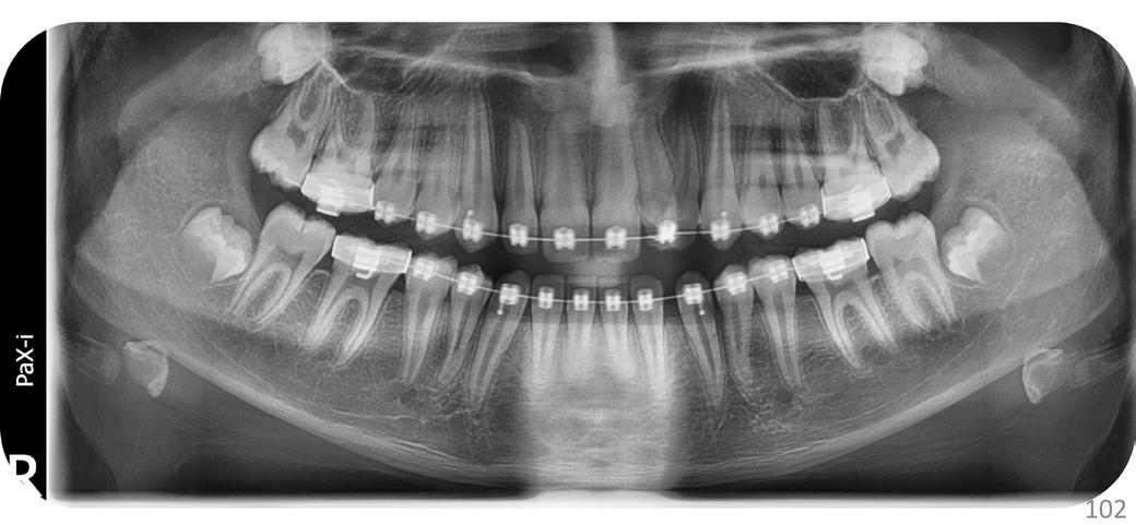
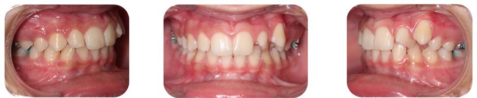
In this paper, we report a case of a geminated maxillary left lateral incisor that was treated with a team approach.
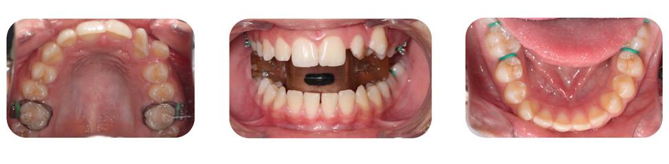
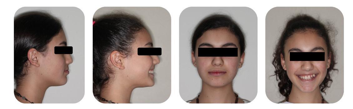
Case Report
A 12-year-old female patient presented to our clinic with a chief complaint of anterior upper crowding. Her medical history was uneventful. Clinical and dental cast examinations showed an oversized maxillary left lateral incisor (15mm in width) that was rotated “mesial-out,” combined with a slight class II relationship on the left side, a symmetrical face and a straight profile. Overbite was 50%, whilst overjet was 3mm (Fig. 1 and 2).
It was decided that the tooth would benefit from hemisection, in order to transform it into a regular sized lateral incisor. Brackets were bonded and alignment was initiated.
Then, a root canal treatment of the double tooth was done; after anesthesia (Mepivacaine 3%, 1/100 000), and rubber dam placement, two distinct access cavities were made from the palatal surface. Working length was established with the use of an apex locator (Root ZX, Mini, J. Morita Corp., Tokyo, Japan) and verified with a periapical radiograph. Shaping was done using Reciproc R25. Copious amounts of sodium hypochloride 6%, with ultrasonic activation (EDDY, VDW GmbH, Munich, Germany), were used to disinfect the root canals and remove the debris. The canals were filled using gutta-percha and zinc oxide sealer (SealiteTM Regular, Acteon, Pierre Roland, France) with the continuous wave technique.
The endodontic treatment was then followed by root separation using a dental burr, then an extraction of the distal root (Fig. 4). Orthodontic treatment was then continued (Fig. 5).
Tooth 22 responded positively to thermal pulp testing.
Radiographic evaluation of tooth 22 showed two distinct roots. In addition to the panoramic and the lateral cephalogram, a CBCT exam was done in order to study the canal anatomy; it revealed a small connection between the two pulp chambers at the cervical level (Fig. 3).
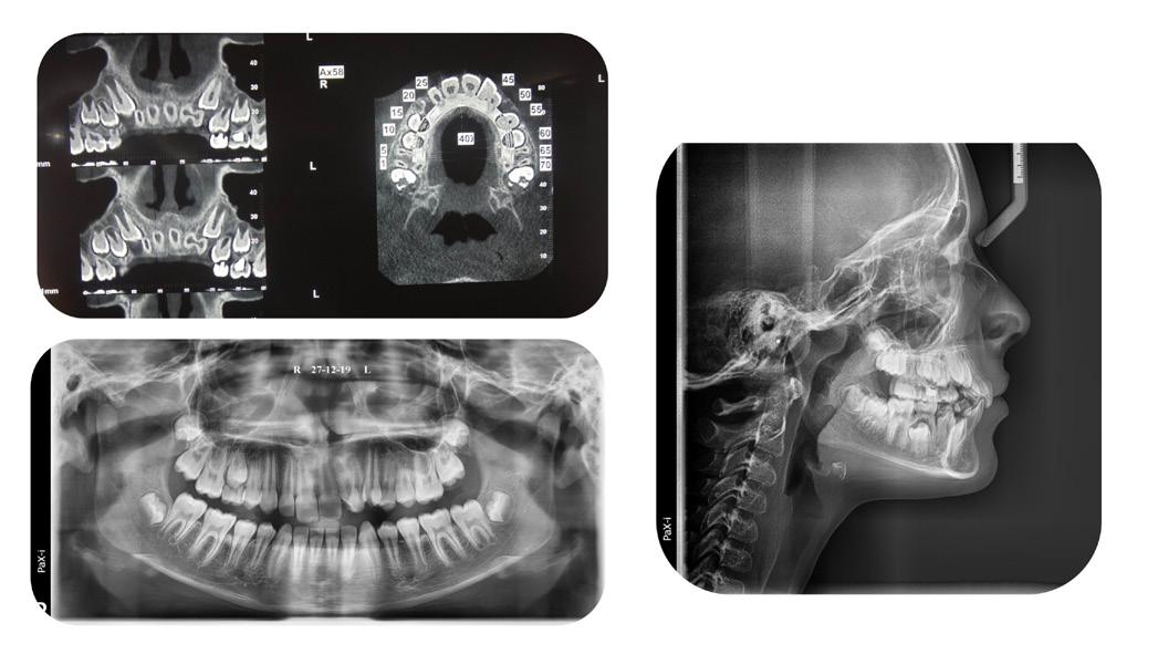
33 33
Figure 1: Initial extra-oral pictures
Figure 2: Initial intra-oral pictures
Figure 3: Initial radiographic exam
Figure 4: Panoramic x-ray during initial orthodontic treatment
A satisfactory result was obtained. Total treatment time was 18 months. The patient was advised to have a crown restoration on the tooth, but was pleased with the end result and decided to postpone it for the time being (Fig. 6 and 7).
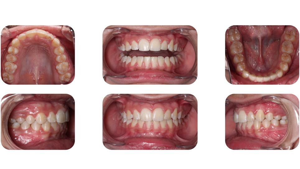
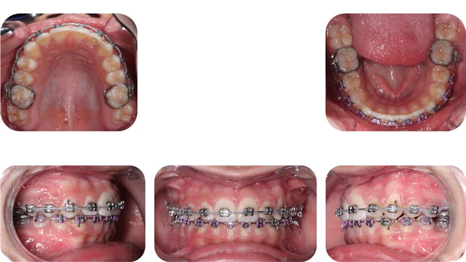
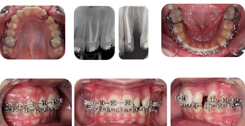
challenging and requires a multi-disciplinary approach. Hemisection was indicated in this case because two separated roots were observed, with connecting pulp chambers.7
An alternative option would have been extraction of the giant tooth followed by an implant, but this option was rejected due to the patient’s young age.
Conclusion
Despite being a rare phenomenon, the treatment of a geminated tooth can be quite challenging for the practitioner; a multi-disciplinary team approach should therefore be the gold standard of treatment, ensuring a conservative individualized end result.
References
1. Proffit WR, Fields Jr HW, Sarver DM. Contemporary orthodontics. Elsevier Health Sciences; 2006.
2. Le Gall M, Philip C, Aboudharam G. Orthodontic treatment of bilateral geminated maxillary permanent incisors. Am J Orthod Dentofac Orthop Off Publ Am Assoc Orthod Its Const Soc Am Board Orthod. 2011 May;139(5):698–703.
3. Altug-Atac AT, Erdem D. Prevalence and distribution of dental anomalies in orthodontic patients. Am J Orthod Dentofac Orthop Off Publ Am Assoc Orthod Its Const Soc Am Board Orthod. 2007 Apr;131(4):510–4.
4. Hamasha AA-H, Al-Khateeb T. Prevalence of fused and geminated teeth in Jordanian adults. Quintessence Int Berl Ger 1985. 2004 Aug;35(7):556–9.
5. Barbério G, Costa S, Rios D, Oliveira T, Machado M. Rare Case of Bilateral Gemination in Deciduous Teeth. Int J Morphol. 2013 Mar;31:575.
6. Brook AH, Winter GB. Double teeth. A retrospective study of “geminated” and “fused” teeth in children. Br Dent J. 1970 Aug 4;129(3):123–30.
7. Cetinbas T, Halil S, Akcam MO, Sari S, Cetiner S. Hemisection of a fused tooth. Oral Surg Oral Med Oral Pathol Oral Radiol Endod. 2007 Oct;104(4):e120-124.
Discussion
Gemination/fusion is a rare phenomenon that occurs in less than 1% of the population. Establishing a differential diagnosis between the two can be challenging. The etiologies are unclear, but include trauma, vitamin imbalances, genetics, environmental factors and some neurological disorders.1,2,3,4
The treatment of double teeth can be quite
34
Figure 5: Orthodontic treatment, root canal treatment and hemisection
Figure 6: Orthodontic treatment progress pictures
Figure 7: End result intra-oral pictures.
Aligner Time Wear
By Dr. Stephane Reinhardt, DMD, Director of Education Program for The C.L.E.A.R. Institute Inc., www.theclearinstitute.com
Introduction
Clear aligners have become a popular alternative to traditional braces for correcting dental malocclusions. The Invisalign® clear aligner system has been used by practitioners for many years and its effectiveness has been well documented. However, there is still ongoing research to determine the best protocol for wearing clear aligners. This article aims to discuss the latest findings on the protocol for wearing Invisalign® clear aligners, as well as provide recommendations for dental practitioners.
Historical Protocol for Wearing Invisalign® Clear Aligners
In the past, the recommended protocol for wearing Invisalign® clear aligners was to change them every 14 days. However, the material used for the manufacture of the aligners was different at that time, making them more rigid and difficult for patients to change every week. This led to some patients reporting that the second week of wear was useless, which prompted some practitioners to begin changing the aligners every week. Clinical experience has shown that changing the aligners every week can lead to better results for most cases.
Recent Research on Invisalign® Clear Aligner Wear Protocol
A recent randomized clinical study conducted by Al-Nadawi et al. (published in the journal Angle Orthodontist, 2022) compared wearing aligners for 7, 10, and 14 days. Eighty patients were selected, and digital scans were taken throughout the study to
assess the movement and final position of the teeth. The study demonstrated that the 14-day protocol had greater efficiency and precision of movements, although the difference was statistically significant but not clinically significant. It is, therefore, not advantageous to double the wear time to achieve the difference. Recommendations for Dental Practitioners: The CLEAR Institute recommends changing the aligners every week, as this has been shown to be the most effective method for the majority of cases. Decreasing the velocity of each aligner’s movement while continuing to change them every week is recommended for cases where some teeth are harder to move. Customizing the protocol for each patient can lead to better compliance and the success of cases.
Conclusion
The protocol for wearing Invisalign® clear aligners continues to evolve, and practitioners must stay up-to-date with the latest research to provide the best treatment options for their patients. While there have been some changes in the recommended protocol for wearing clear aligners, the most important factor is to ensure patient compliance. By making the process easier and more simplified for patients, practitioners can help to ensure the success of their cases.
If you would like to see a video version of this blog, follow this link to The CLEAR Institute’s YouTube channel: What is the best wear time for Invisalign clear aligner patients?
35 35
Clear Aligners Corner
The Ergonomic Hybrid Mini-Implant Driver (The
Universal 2.0)
By Dr. Priyank Rai, BDS, MDS and Dr. Amrin Rizwana, BDS


Abstract
Maulana
The palatal vault is a useful site for mini-implant insertion due to the presence of adequate attached gingiva and thick cortical bone. The biggest challenge is the insertion of a miniscrew, which requires either a self-drilling or pre-drilling palatal mini-implant kit system. These kit systems provide drivers for different mini-implant sizes, which are of unique design and great quality, but are expensive and not economical. Hence, we designed a multipurpose small plus-shaped driver for mini-implant placement that can be used in the narrow palatal vault, inter-radicular region, and the extra-alveolar site. It is an economical substitute for the long, straight hand-held driver. It can be used in confined intraoral space like the palatal region as straight drivers will interfere with lower teeth.
.New Delhi, India *This
Description of the Driver
A 2.0mm straight hand-held driver of the commercially available self-drilling mini-implant system was used. This driver has a head with a slot of 2.0 mm diameter, a body, and a shaft (Fig. 1). The shaft gets snugly inserted into the handle (Fig. 2).
Fabrication:
This 2.0mm driver was segmented into three pieces (Fig. 3) i.e., the head, the body, and the shaft. These were rearranged to a plus shape with the body of the driver placed horizontally. The length of the body is 20mm based on the palatal width (half the intermolar distance) to provide sufficient room for the manipulation of the driver. At this position, the head and the shaft of the driver were soldered in the
36
Featured*
Dr. Priyank Rai, BDS, MDS
Senior Professor • Deparment of Orthodontics
Azad InstituteoOf Dental ,Sciences
.New Delhi, India
Dr. Amrin Rizwana, BDS
Post Graduate Student Department Of Orthodontics
Maulana Azad Institute Of Dental ,Sciences
article has been peer reviewed
center of the body on either side (Fig. 4). It is referred to as a hybrid as it can be used with or without the handle (Fig. 5).
Placement
The miniscrew is held within the 2.0mm slot of the newly fabricated driver. The miniscrew and the driver are secured with dental floss to prevent any slippage or aspiration. The “PLUS” portion of the driver is used without the handle for initial insertion (Fig. 6) as well as for the rotation movement of the mini-implant (Fig. 7). This design enhances the grip and the tactile sensation while driving the miniscrew into the palate. It can be used in narrow anterior and posterior parts of the maxillary palatal vault without any interference.
Clinical Use
1. Used in the narrow palatal vault as it does not interfere with lower teeth (Fig. 8) .
2. Used in the buccal (Fig 9) and extra-alveolar sites (Fig. 10).
CONCLUSION:
The hybrid mini-implant driver is versatile, efficient, and economical. It can be used at various sites intraorally. Hence, this patient-friendly driver can be considered to be a good alternative to the expensive mini-implant systems to fulfill the same treatment objectives.
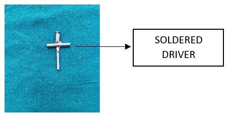

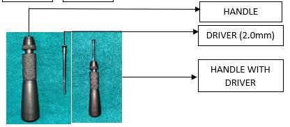
37 37
Figure 1 (left): Depicts the image of the commercially available mini-implant driving handle with the driver (2.0mm).
Figure 2 (right): Depicts the image of the handle-driver assembly with the driver mounted on the handle.
Figure 3 (left): Depicts the image of the driver after sectioning into the head, body, and shaft where the body is placed in a horizontal position.
Figure 4: Depicts the image of the driver after soldering all 3 parts.
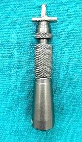
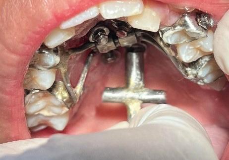
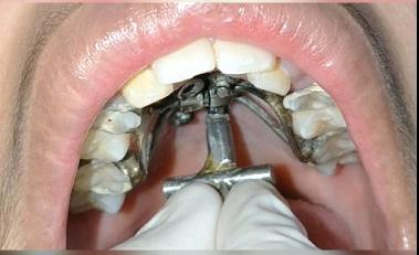
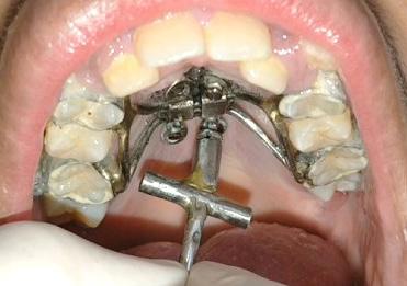
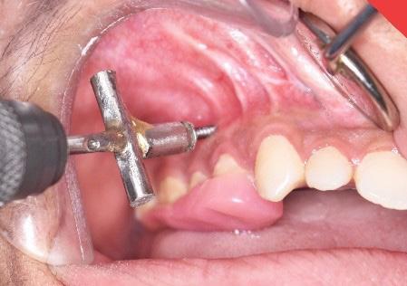
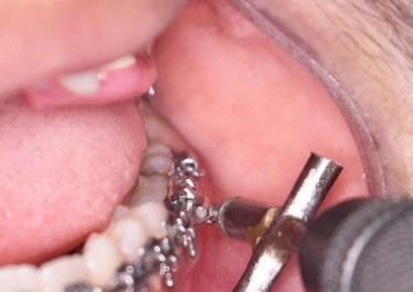
38
Figure 10: clinical representation of extra-alveolar usage of
Figure 5: Depicts the image of the driver mounted to the handle.
Figure 6: Clinical representation with the driver being used for palatal mini-implants.
Figure 7: Clinical representation with the driver being used for palatal mini-implants.
Figure 8: clinical manipulation by holding the crossbody of the driver (type of grasp for improved tactile sensation and enhancing the grip)
Figure 9:clinical representation of inter-radicular usage of the driver.
The D-Gainer Appliance Part 1
By Dr.Adrian J. Palencar,
 FADI, FPFA, FICD
Dr. Palencar is an IAO Master Senior Instructor, IAO Education Committee Examiner, and a Consultant to the IJO and Spectrum Ortho.
The definition of the D-gainer appliance from Google: “The D-Gainer appliance is used instead of a palatal expander to eliminate crowding in the upper jaw and to allow for a wider smile.”
The above is a succinct statement. However, it does not reflect all the attributes of this wonderful appliance. “D” stands for distance gainer; therefore, the primary function is a reciprocal anterio–posterior movement of teeth. The expansion is just a byproduct of the mesio-distal forces. Also, D-Gainer appliance slightly bows out - keeps the cheeks away, therefore allows lateral development of the alveolar process (Frankel appliance effect).
The author was introduced to D-Gainer appliance by Dr. Derek Mahony, an orthodontist from Australia several years ago. Dr. Mahony treats many patients in the mixed dentition with moderate crowding, who require 5-6 mm expansion, successfully with the D-Gainer appliance. If more expansion is needed (i.e., splitting the Mid-palatal suture) a functional appliance should be used. More details are available on YouTube under “Dr. Derek Mahony, D-Gainer.”
The D-Gainer appliance is most efficient in 2x4 or 2x6 set up and it is effective in both arches.
The following are the functions of the D-Gainer appliance:
1. Mesial moment (proclination) and bodily movement of incisors
2. Distal moment (distalization) of molars
3. Transverse development (bowing out the arch wire and the Frankel effect)
4. Vertical development (up righting the molars)
5. Shifting the midline (more force on one side, less or no force on the other side)
The treatment:
1. Place and bond brackets and tubes on the first permanent molars (or second deciduous molars) and four incisors
2. Level four incisors (a .014 and a .018 NiTi) sectional arch wire
3. If the molar tubes ale leveled try to insert a .018 SS, cut it 10 mm past the tube
4. Measure the open coil springs exactly from the molar tubes to the brackets on the lateral incisors and add exactly 4,0 mm, and cut it
5. Inser t NiTi Open Coil Springs on the arch wire
39 39
Tips from the Experienced
MUDr, MAGD, IBO,
Dr. Adrian J. Palencar
6. Insert and tie the arch wire or close the latches on PSL brackets
7. Leave 5.0 mm of straight wire behind the molar tube and then place 90-degree bend-back
It is possible to grow new bone facially by orthodontic forces, by not compressing the blood vessels on the compression side. Keeping the force levels below 32 grams of force, thus avoiding necrosis of the PDL cells (Dr. Ed Lipskis).
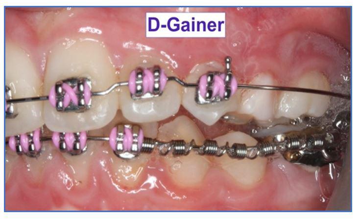
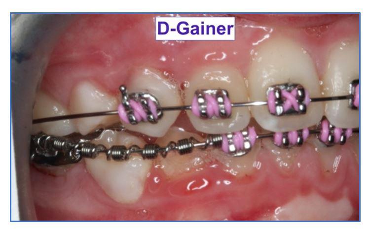
If the second deciduous molars are still firm, it is advantageous to bond the tube on this tooth, thus double the posterior anchorage. The images below demonstrate this set up in the mandible.
References
1. Andrews L. A.; Straight Wire the Concept and Appliance
2. English J. D.; Orthodontic Review. 85 – 87
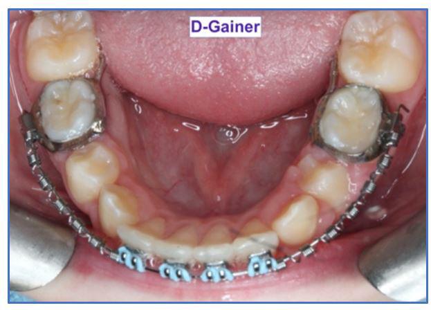
3. Rondeau Seminars; Introduction to Orthodontics, Level I, Session 2; 1 - 15
International Journal of Orthodontics Reviewers Needed
Do you have a passion for cutting-edge orthodontic journalism?
Do you believe the sharing of knowledge betters the communities IAO members serve?
Are you interested in raising the standards of practice by disseminating information through a respected and readily available resource?
If so, then we invite you to join the International Journal of Orthodontics (IJO) Reviewer team.
It is your turn to be a part of this internationally recognized, prestigious publication
IJO Reviewers read articles to assess their suitability for publication. If said articles do not meet the standards of this highly respected journal, the reviewer will note issues and provide feedback for needed improvements. You can take pride in the impact your expertise will have on informing the orthodontic community.
The IJO is looking for general reviewers, particularly those with expertise in the following disciplines:

• Growth & Development
• TMJ
• Orthognathic and osseous modification treatments
To Learn More or
Pasch at paschrob@rogers.com
to Volunteer, Contact Dr. Rob
