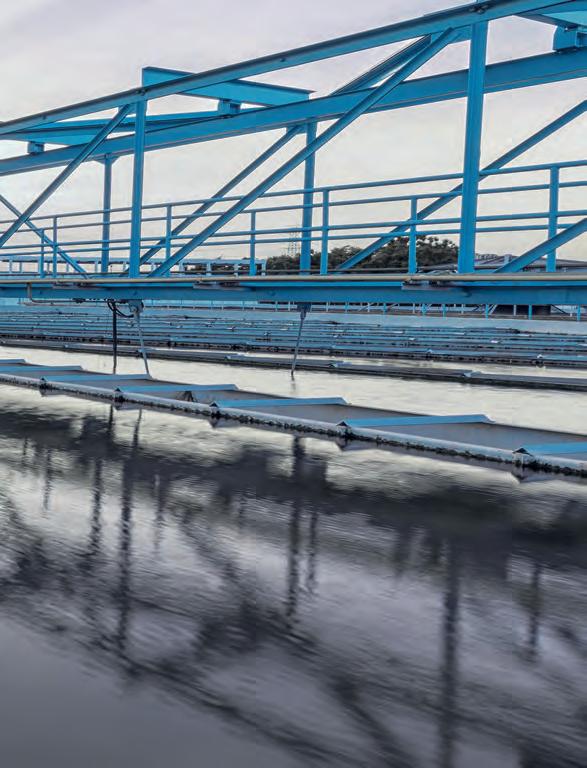
PUMPS FOR WASTEWATER TREATMENT
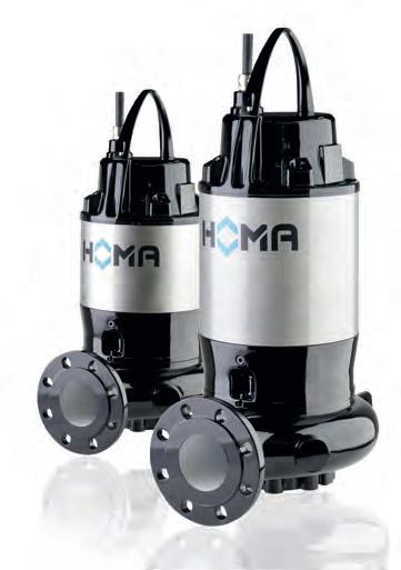
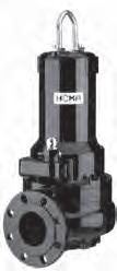
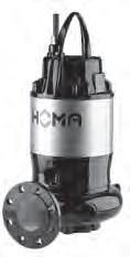
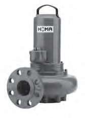
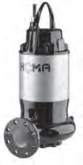
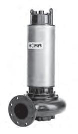
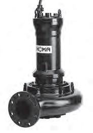
SUBMERSIBLE SEWAGE PUMPS
HIGH EFFICIENCY AND ECONOMIC VIABILITY
Submersible pumps from HOMA have been in use around the world for decades. Requirements for the waste water sector are constantly increasing. HOMA products go beyond state of the art – through the continual optimisation of their hydraulic components and motors, they ensure economic operation and an affordable purchase price. All of the company’s expertise and creative potential have been incorporated into its products and services – for maximum customer benefit.
INDIVIDUAL POSSIBILITIES, OPTIMUM SOLUTIONS
HOMA unites safety, economic viability, high quality and robust system technology with customisation options: the product spectrum ranges from complete pump stations with pumps, valves, pipework, pre-assembled concrete or plastic sumps, through to electronic control systems. The focus is on optimum design with cost effective workflows on site for all installation types.
HIGHER FUNCTIONAL RELIABILITY, LOWER ENERGY CONSUMPTION
With HOMA you are always in good hands – our pump stations are controlled and monitored fully automatically, and faults are registered automatically, too. The pumps run with the lowest possible energy consumption, which is also ensured by optimally matched water level control devices, such as floats, pneumatics, ultrasound and hydrostatic level sensors (ENS sensors).
In many cases, both the pump and control system have to meet the relevant requirements and regulations on explosion protection. All HOMA pumps are therefore also available as explosion-proof versions.
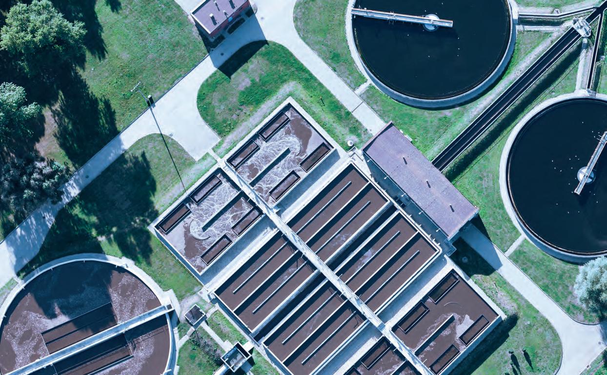
MULTIPLE DEMANDS – INDIVIDUAL SOLUTIONS
Submersible waste water pumps from HOMA convey domestic, public and industrial waste water, sewage (containing faeces), and sludge (which may contain high levels of solid and fibrous matter), as well as domestic waste water of any kind. Thanks to the use of a broad range of materials (stainless steel in different grades, bronze, Viton, etc.), HOMA submersible pumps are suitable for a wide variety of industrial applications.
• Industrial waste water
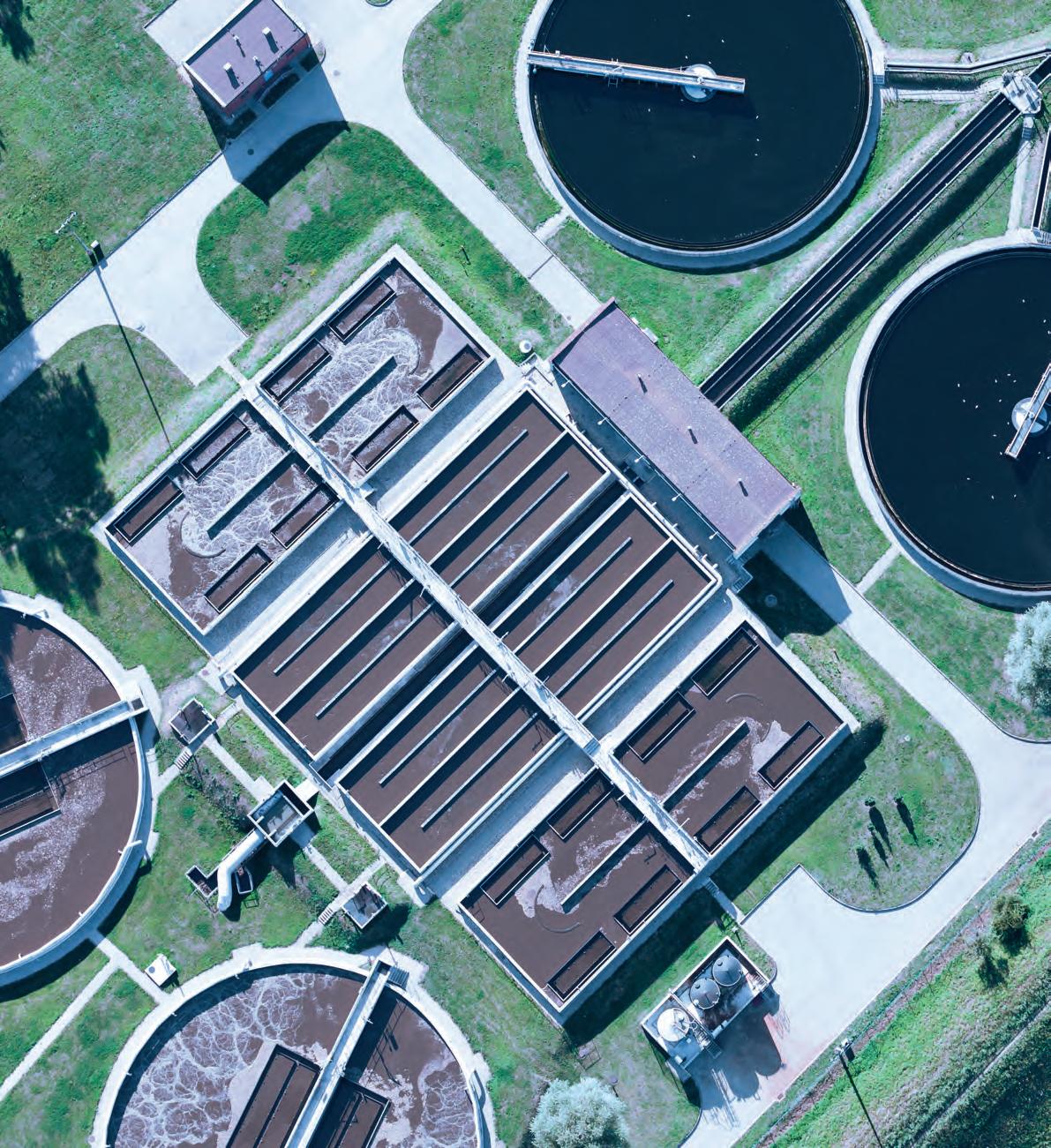
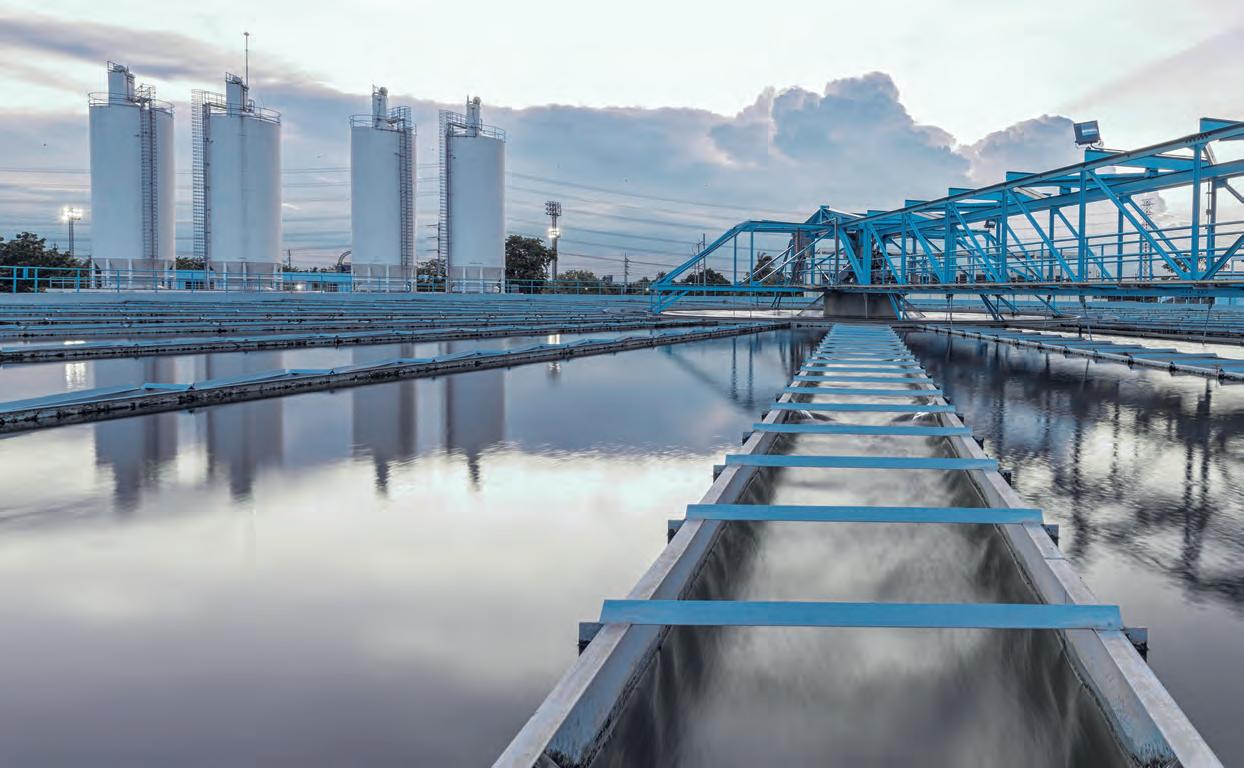
• Sewage treatment plants
• Large scale pump stations
• Industrial applications
• Oil and gas
• Power station construction
• Mining
• Chemical processes
• Shipbuilding/offshore sector
MORE POWER FOR EVERY REQUIREMENT
HOMA pumps are used in all manner of applications: to supply water to power stations, as seepage pumps in coal mines, drainage pumps in infrastructure projects, waste water pumps for industrial waste water, or as ballast pumps in the shipbuilding and marine sector. Customers benefit from proven features tried and tested in real life applications, such as:
• A range of different impellers, depending on the medium being conveyed, e.g. special symmetries, hardened materials and ceramic coatings
• Motors suitable for continuous operation, with or without cooling jackets
• High grade materials
• Robust construction
For operating mode S1 (continuous operation), the motors are designed with a maximum switching frequency of 20 operating cycles per hour. In addition to the standard version for operation with a submerged motor, a special version with cooling jacket is also available for use with a surface motor or dry installed motor.
Hydraulics with single-channel impellers are suitable for intermittent operation (i.e. generally for level-controlled automatic sump operation) and continuous operation. Vortex or multi-channel impellers are the right choice for continuous operation in particular, e.g. for industrial service water supply.
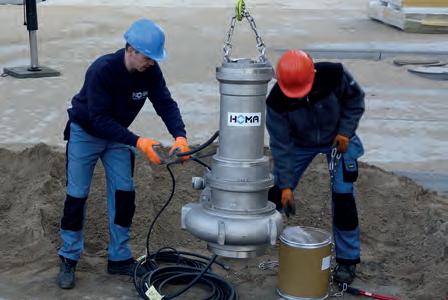
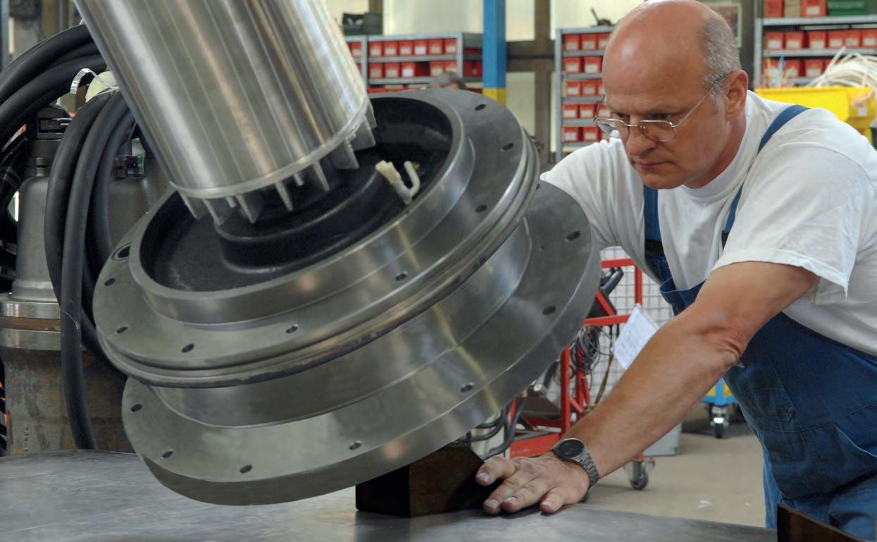
TOP MATERIAL QUALITY –LOWER SUSCEPTIBILITY TO FAILURE
Quality is a measurable value – fully floodable pump blocks from HOMA impress through their generous sizing of all important components, with outstanding material quality and solid mechanical workmanship. This guarantees a long service life
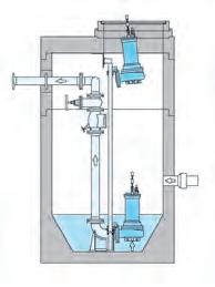
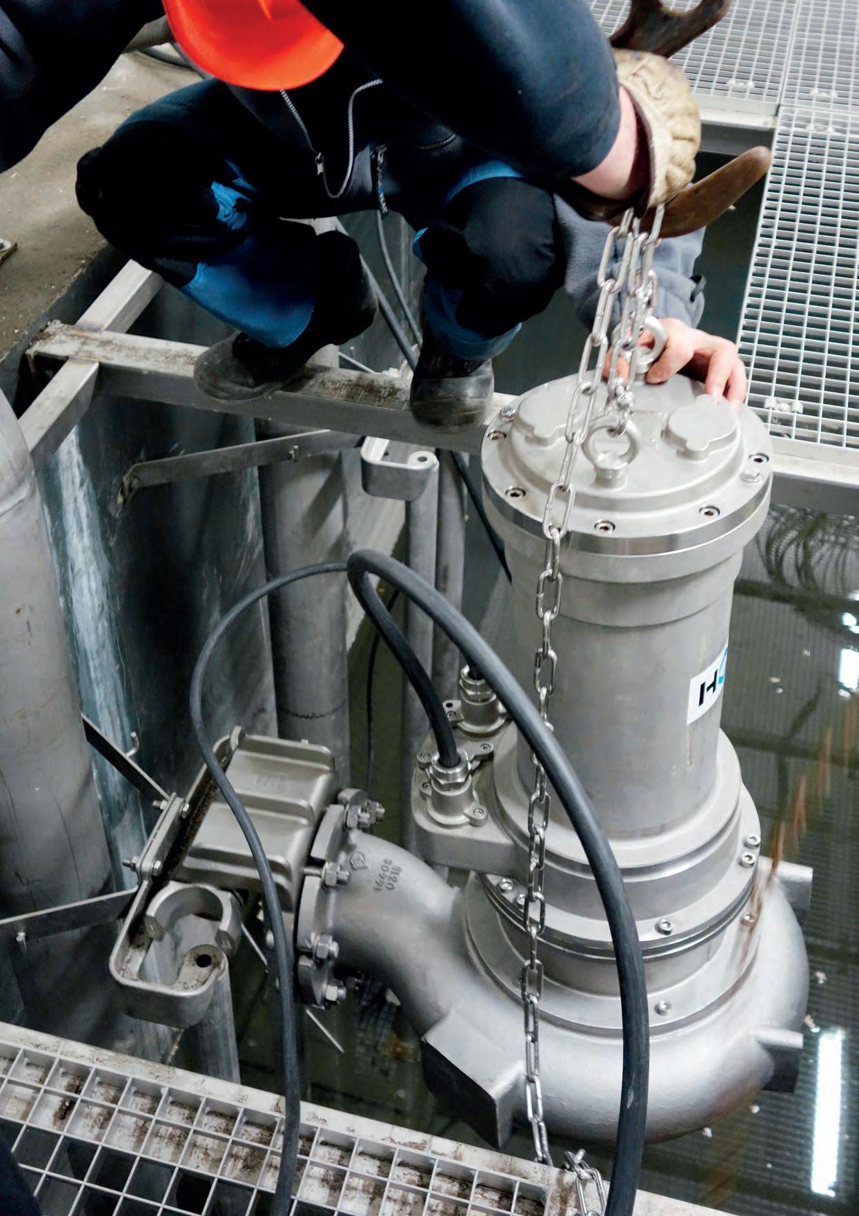
STATIONARY WET WELL INSTALLATION
The pump is connected to the pressure pipe and is made pressure-tight by means of a coupling base attached to the bottom of the sump. For maintenance or repair, it can be removed from its operating position from above through the sump opening via a permanently installed double pipe feed. The pump is attached and detached automatically; it is not necessary to enter the sump. With its flexible rubber gasket, the HOMA coupling system thereby ensures a secure, permanent, leak-free seal between the pump and the pressure pipe.
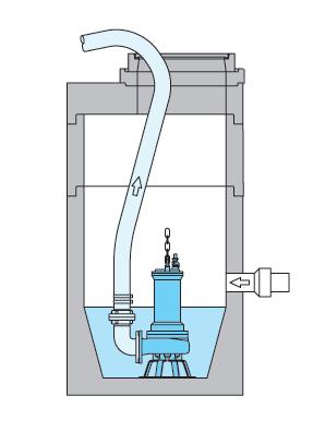
MOBILE WET WELL INSTALLATION
Universal installation for immersion in trenches and sumps, for use over a limited period, emergency operation or service operation. Can be used with a pressure hose or pressure pipe.
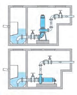
STATIONARY DRY INSTALLATION –VERTICAL OR HORIZONTAL
Flood-proof installation for pump stations with a separate collection sump. Flange connection for suction pipe and pressure pipe.
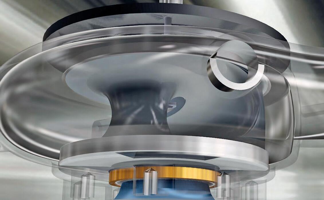
MXS: IMMUNITY TO CLOGGING
Conveyed media have changed greatly in recent years, displaying an increasing solids content. In order to ensure reliable operation in such cases, our new MXS hydraulics rely on closed single-vane impellers with large free passages.
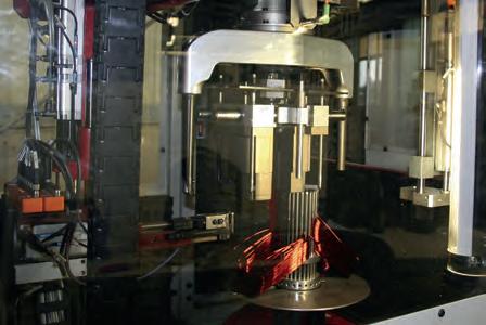
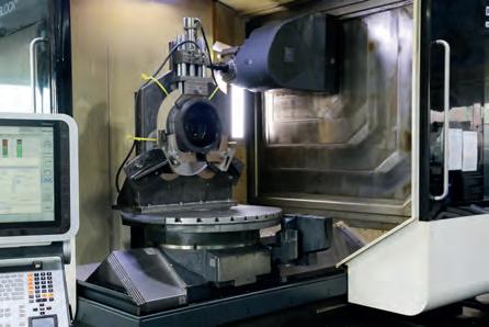
Our impellers and pump housings have been redesigned at the HOMA R&D center and optimized with the latest flow-simulation software. The result: clearly improved hydraulic efficiencies of up to 81 percent, with a simultaneously low risk of blockage and quiet running. In combination with HOMA‘s proven submersible-motors, the new MXS hydraulics are setting a trend in economic efficiency and operational safety.
EFFTEC: INNOVATIVE TECHNOLOGY
In order to achieve the highest possible overall efficiency with consequently low energy consumption we developed the new EffTec series at our HOMA R&D center. In combination with the new MXS hydraulics, the new pump generation is setting a trend in economic efficiency and operational safety.
The newly developed PermaCool system is futureoriented. This permanent motor cooling now gives you the option of fitting the units for submerged or drywell installation. The new design - registered for a patentsimultaneously ensures that the cooling jacket cannot be clogged with solids.
Together with the low winding temperature of the EffTec motors, the PermaCool system puts a low thermal load on all components, thus ensuring their long useful lifetime.
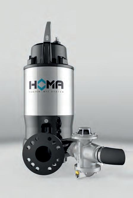
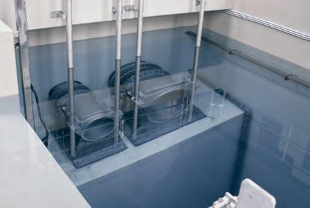
FLUSH VALVES: KEEPING IT CLEAN
Pump stations require frequent cleaning as solids settle at the bottom or a layer of floating matter gathers on the surface of the water. Expensive cleaning and maintenance measures as well as high costs due to downtimes can arise. HOMA has the answer: the new HOMA FV 25 and FV 50 flush valves reliably prevent deposits in pump sumps. At the beginning of the pumping process, part of the medium being handled is channelled back to the pump sump through the open flush valve. As the medium is flushed through the sump, it stirs up deposited solids so that they can be removed.
The flushing nozzle can either be directed towards the bottom of the pump sump to remove deposits, or alternatively, towards the surface of the waste water to prevent the formation of a layer of floating matter, especially in the case of waste water with a high fat content.
MOTOR SELECTION
Speed:
For the standard hydraulic range, the motors are designed with the following speeds.
• 2900 rpm = 2-pole
• 1450 rpm = 4-pole
• 960 rpm = 6-pole
Voltages:
All specified data relate to an operating voltage of 400V/3 Ph,50 Hz. Different voltages are available on request.
Type of start:
In the standard version, pumps are supplied for direct start and star-delta start.
All motors are available for frequency converter and soft start operation.
Explosion protection:
Depending on the assembly group, also available in explosion-proof design.
Dry well variant:
Besides the version for submerged operation, all pumps are also available with cooling jacket for dry well or non-submerged operation.
Motor monitoring:
All motors are supplied with temperature sensors in the winding, bi-metallic sensors (standard), PTC thermistor or PT100 (on request).
Depending on version available with:
• oil chamber monitoring probe
• moisture monitoring of the cable connection chamber
• moisture monitoring of the stator chamber
• Temperature monitoring of bearings
HYDRAULIC SELECTION
Discharge and suction flange
• DN 80
• DN 100
• DN 150
Reducing adapters for different auto-coupling system and valve dimensions are available.
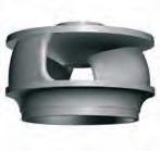
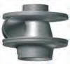
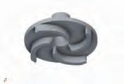
Impeller:
A range of different impeller designs are available to provide optimum performance and reliability with various liquids and operating conditions.
Impeller spherical clearance:
The pumps are available with impeller spherical clearances from 80 mm to 100 mm according to pump range.
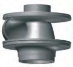
MXS
Enclosed single channel impeller
For liquids containing impurities and sludge with solid particles or long fibers. New generation of non clogging impellers with hydraulic efficiency over 80%.
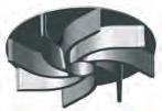
K(X)
Enclosed Multi Channel Impeller
For liquids containing impurities and sludge with solid particles.
V(X)
Vortex impeller
For liquids containing a high level of impurities or fibrous matter and containing gas.
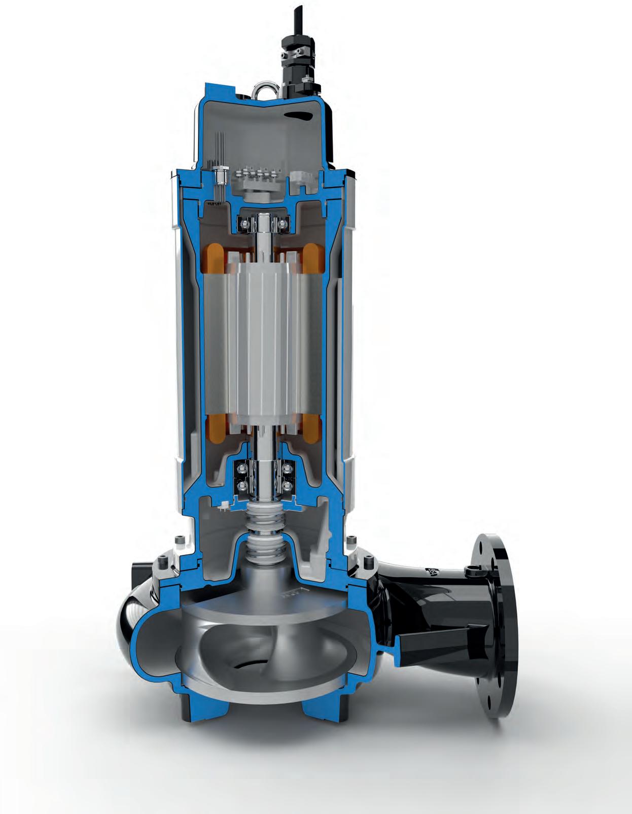
Quality can be measured – HOMA submersible waste water pumps are characterized by the robust design, generous dimensioning and high quality materials of all components.
A DISCHARGE
With DIN/ANSI flange DN 80, DN 100 or DN 150 (PN 10)
B NON-CLOGGING IMPELLERS
• Enclosed single channel impeller with large spherical clearance. Replaceable wear ring.
• Enclosed multi channel impeller with replaceable wear ring
• Vortex impeller
C SHAFT SEALS
Two independently working silicon-carbide mechanical seals in tandem-arrangement.
D OIL CHAMBER
Oil-filled sealing chamber with screw for inspection. All motors with seal monitoring in the oil chamber as standard.
E MOTOR
Three phase electric motor with 2-, 4- or 6-pole winding. Insulation class H (180º C), Protection IP 68.
EXPLOSION PROTECTION
Depending on the assembly group, also available in explosion-proof design.
F MOTOR COOLING
Motors for submerged operation are cooled by the surrounding liquid. For dry well or non-submerged operation, motors are available with a cooling jacket, providing a cooling circulation of water from the pump volute (model U).
G MOTOR WINDING
Motor winding with temperature monitoring by bimetal switch. PTC thermistor and PT100 on request.
H SHAFT BEARINGS
Robust, maintenance-free, permanently lubricated roller bearings. Temperature monitoring of shaft bearings on request.
I JUNCTION CHAMBER
Water pressure-tight encapsulated cable connection compartment, standard for F(U), G(U) motor. Optional for P(U) motor.
J CABLE INLET
Water pressure-tight cable inlet with cable H07RN8-F. Shielded cable on request.
K MOTOR MONITORING
11.1 Seal monitoring of oil chamber (standard)
11.2 Seal monitoring of motor housing (on request)
11.3 Seal monitoring junction chamber (Standard for F and G motor. P(U), FU, GU motor optional)
11.4 Temperature monitoring of winding by bimetal switch (standard). PTC thermistor and PT100 on request
11.5 Temperature monitoring of upper and lower bearings by PT100 (on request)
Wear rings
Motor shaft
Mechanical seals
Motor cooling jacket (model U)
Seals and O-rings
Cable H07RN8-F
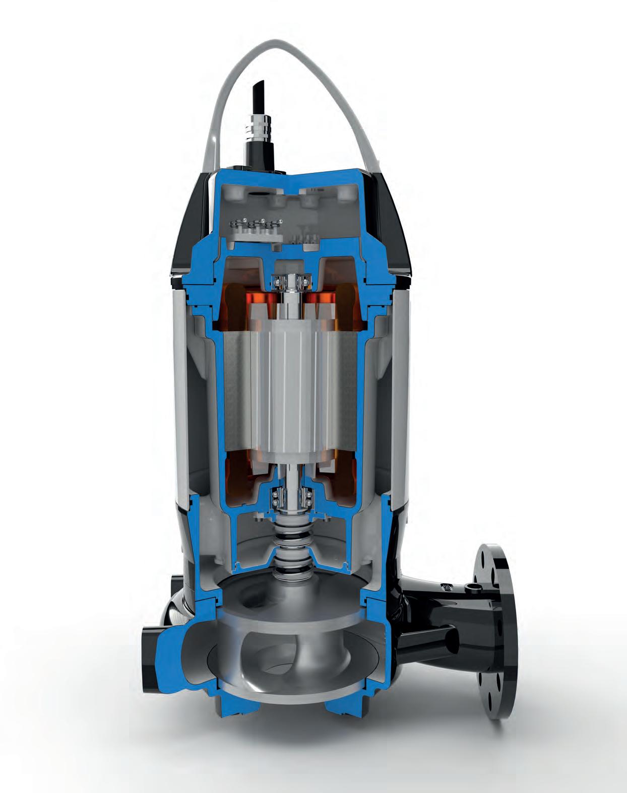
All models in the EffTec series are equipped with the newly developed PermaCool system. This permanent motor cooling now gives you the option of fitting the units for submerged or drywell installation. The new design - registered for a patentsimultaneously ensures that the cooling jacket cannot be clogged with solids. In combination with our new MXS-hydraulics, the new EffTec series of pumps sets a trend for economic efficiency and reliability.
A DISCHARGE
With DIN/ANSI flange DN 80, DN 100 or DN 150 (PN 10).
B NON-CLOGGING IMPELLERS
• Enclosed single channel impeller with large spherical clearance. Replaceable wear ring.
• Vortex impeller.
C SHAFT SEALS
Two independently working silicon-carbide mechanical seals in tandem-arrangement.
D OIL CHAMBER
Oil-filled sealing chamber with screw for inspection. All motors with seal monitoring in the oil chamber as standard.
E MOTOR
Three phase electric motor with 2-, 4-, or 6-pole winding. Insulation class H (180 C), Protection IP 68.
EXPLOSION PROTECTION
Depending on the assembly group, also available in explosion-proof design.
F MOTOR COOLING PERMACOOL
This permanent motor cooling now gives you the option of fitting the units for submerged or drywell installation.
Together with the low winding temperature of the EffTec motors, the PermaCool system puts a low thermal load on all components, thus ensuring their long useful lifetime.
Motor winding with temperature monitoring by bimetal switch. PTC thermistor and PT100 on request.
H SHAFT BEARINGS
Robust, maintenance-free, permanently lubricated roller bearings. Temperature monitoring of shaft bearings on request.
J CABLE INLET
Water pressure-tight cable inlet with cable H07RN8-F. Shielded cable on request.
11.1 Seal monitoring of oil chamber (standard)
11.2 Seal monitoring of motor housing (on request)
11.4 Temperature monitoring of winding by bimetal switch (standard). PTC thermistor and PT100 on request
11.5 Temperature monitoring of upper and lower bearings by PT100 (on request)
MATERIALS
Motor housing Cast Iron EN-GJL-250
Pump housing Cast Iron EN-GJL-250 (stainless steel optional)
Impeller Cast Iron EN-GJL-250 (stainless steel optional)
Wear ring Bronze
Motor shaft Stainless Steel
Mechanical sealsSilicon Carbide / Silicon Carbide
Cooling jacket Stainless Steel
Seals / O-RingsPerbonane NBR (Viton FPN optional)
Cable H07RN8-F
Enclosed single channel impeller
80 mm Ø
Spherical clearance 2900 rpm

17
DN 80
Vortex impeller
80 mm Ø
Spherical clearance 2900 rpm

19
Enclosed single channel impeller
80 mm Ø
Spherical clearance 1450 rpm
18
Vortex impeller
80 mm Ø Spherical clearance 1450 rpm
20
Enclosed single channel impeller
80 mm Ø
Spherical clearance 2900 rpm
MXS23... -2 pole
MXS23... -4 pole PAGE 21
Enclosed two channel impeller
80 mm Ø
Spherical clearance 1450 rpm

-4 pole PAGE 23
Enclosed single channel impeller
100 mm Ø
Spherical clearance 960 rpm
MXS24... -6 pole
Enclosed single channel impeller
80 mm Ø
Spherical clearance 1450 rpm
MXS24... -4 pole
Enclosed single channel impeller 100 mm Ø
Spherical clearance 1450 rpm
22 PAGE 24
VX24... -4 pole
Vortex impeller
100 mm Ø
Spherical clearance 1450 rpm
PAGE 25 PAGE 26
Enclosed single channel impeller
100 mm Ø
Spherical clearance 1450 rpm
Enclosed single channel impeller 100 mm Ø
Spherical clearance 960 rpm
Enclosed two channel impeller 80 mm Ø
Spherical clearance 1450 rpm
Enclosed two channel impeller 80 mm Ø
Spherical clearance 960 rpm
Enclosed single channel impeller
80 mm Ø Spherical clearance
HYDRAULIC PERFORMANCE
2900 rpm Technical data
Enclosed single channel impeller
80 mm Ø Spherical clearance 1450 rpm
Technical data
(Ex)
g MXS1340-T34 (Ex) 3,42,95,8 117117
h MXS1340-T44 (Ex)
(Ex)
(Ex)4,43,7 7,7 121121
k MXS1344-T54 (Ex)5,95,09,9 131131
l MXS1346-T54 (Ex)5,95,09,9 131131
m MXS1346-T64 (Ex) 7,7 6,513,1 134134
Technical data
a MXS1328-ET34 (Ex) 3,32,95,9 128128
b MXS1330-ET34 (Ex) 3,32,95,9 128128
c MXS1332-ET34 (Ex) 3,32,95,9 128128
d MXS1334-ET34 (Ex) 3,32,95,9 128128
e MXS1336-ET34 (Ex) 3,32,95,9 130130
f MXS1338-ET34 (Ex) 3,32,95,9 130130
g MXS1340-ET34 (Ex) 3,32,95,9 134134
h
MXS1340-ET44 (Ex)
Vortex impeller
80 mm Ø Spherical clearance 2900 rpm
Technical data
V1335-T72 (Ex) 11,09,518,8 103103
V1337-T72 (Ex) 11,09,518,8 103103
V1339-T82 (Ex) 13,011,522,2 108108
Vortex impeller
80 mm Ø Spherical clearance 1450 rpm
Technical data
V1334-C24 (Ex) 1,71,33,36364
V1336-C24 (Ex) 1,71,33,36364
V1344-D44 (Ex) 3,42,66,26667
V1346-D44 (Ex) 3,42,66,26667
VX1345-T44 (Ex) 4,43,7 7,7 105105
(Ex) 5,95,09,9 118118
(Ex) 5,95,09,9 118118
(Ex)
Enclosed single channel impeller
80 mm Ø Spherical clearance
2900 rpm
Technical data
(Ex) 11,09,518,8 120120
(Ex)
(Ex) 13,011,522,2 123123
(Ex)
38,035,059,4383383 o MXS2345-F162 43,040,067,5390390 p MXS2346-F162 43,040,067,5390390 Technical data
a MXS2328-ET72 (Ex) 10,59,520,1 146146 b MXS2330-ET82 (Ex) 12,711,522,7 146146 c MXS2332-ET82 (Ex) 12,711,522,7 146146 d MXS2332-PU92 (Ex) 16,014,427,0 189 201 e MXS2334-PU92 (Ex) 16,014,427,0 189 201 f MXS2334-PU102 (Ex) 22,019,636,9 189 201
(Ex) 16,014,427,0 191 203
(Ex) 22,019,636,9 191 203
43,040,067,5 416416
43,040,067,5 416416
Enclosed single channel impeller
80 mm Ø Spherical clearance 1450 rpm
Technical data
Curve No. Pump type
WELL INSTALLATION
(kg) a MXS2328-C24 (Ex) 1,71,33,3 7474 b MXS2330-C24(Ex) 1,71,33,3 7474 c MXS2332-D44 (Ex) 3,42,66,28080 d MXS2334-D44 (Ex) 3,42,66,28080 e MXS2336-D44 (Ex) 3,42,66,28282 f MXS2338-D44 (Ex) 3,42,66,28282 g MXS2340-T34 (Ex) 3,42,95,8 118118 h MXS2340-T44 (Ex) 4,43,7 7,7 122122 i MXS2342-T44 (Ex) 4,43,7 7,7 122122 j MXS2344-T44 (Ex)4,43,7 7,7 122122 k MXS2344-T54 (Ex) 5,95,09,9 132132 l MXS2346-T54 (Ex)5,95,09,9 132132 m MXS2346-T64 (Ex) 7,7 6,513,1 135135 n MXS2350-T64 (Ex) 7,7 6,513,1 142142
o MXS2351-T64 (Ex) 7,7 6,513,1 142142
p MXS2351-ET74 (Ex) 9,88,516,8 168168
q MXS2352-ET74 (Ex) 9,88,516,8 168168 Technical
a MXS2328-ET34 (Ex) 3,32,95,9 128128
b MXS2330-ET34 (Ex) 3,32,95,9 128128
c MXS2332-ET34 (Ex) 3,32,95,9 128128
d MXS2334-ET34 (Ex) 3,32,95,9 128128
e MXS2336-ET34 (Ex) 3,32,95,9 130130
f MXS2338-ET34 (Ex) 3,32,95,9 130130
g MXS2340-ET34 (Ex) 3,32,95,9 135135
h
i
MXS2340-ET44 (Ex) 4,33,7 7,3 135135
MXS2342-ET44 (Ex) 4,33,7 7,3 135135
j MXS2344-ET44 (Ex)
Enclosed two channel impeller
80 mm Ø Spherical clearance 1450 rpm
Technical data WET WELL INSTALLATION
Curve No. Pump type
a KX2360-F114 (Ex)25,022,044,0429429
b KX2360-F124 (Ex)29,125,651,4451451
c KX2362-F124 (Ex)29,125,651,4452452
d KX2362-F134 (Ex)32,829,259,0467467
e KX2364-F124 (Ex)29,125,651,4453453
f KX2364-F134 (Ex)32,829,259,0468468
g KX2366-F134 (Ex)32,829,259,0469469
h KX2366-F144 (Ex) 37,133,067,1484484
i KX2368-F144 (Ex) 37,133,067,1485485
j KX2368-G154 (Ex)41,137,470,4502502
k KX2370-G144 (Ex)37,133,067,1486486
l KX2370-G154 (Ex)41,137,470,4503503
m KX2372-G154 (Ex)41,137,470,4504504
n KX2372-G174 (Ex)50,146,184,3532532
a KX2360-FU114 (Ex)25,022,044,0450450
b KX2360-FU124 (Ex)29,125,651,4477477
c KX2362-FU124 (Ex)29,125,651,4478478
d KX2362-FU134 (Ex)32,829,259,0493493
e KX2364-FU124 (Ex) 29,125,651,4479479
f KX2364-FU134 (Ex) 32,829,259,0494494
g KX2366-FU134 (Ex) 32,829,259,0495495 h KX2366-FU144 (Ex) 37,133,067,1 510510 i KX2368-FU144 (Ex) 37,133,067,1 511511
Enclosed single channel impeller
100 mm Ø Spherical clearance 1450 rpm
Technical data
Curve No. Pump type
a
WET WELL INSTALLATION
(kW) (kW)
(A)
MXS2432-T34 (Ex)3,42,95,8 102102
b MXS2436-T34 (Ex)3,42,95,8 104104
c
MXS2438-T34 (Ex)3,42,95,8 104104
d MXS2438-T44 (Ex)4,43,7 7,7 108108
e MXS2442-T44 (Ex) 4,43,7 7,7 129129
f MXS2442-T54 (Ex) 5,95,09,9 139139
g
h
MXS2444-T54 (Ex) 5,95,09,9 139139
MXS2446-T54 (Ex) 5,95,09,9 139139
i MXS2446-T64 (Ex) 7,7 6,513,1 142142
j MXS2450-ET74 (Ex) 9,88,516,8 184184
k MXS2450-P84 (Ex) 14,012,223,0209221
l MXS2454-P84 (Ex) 14,012,223,0209221
m MXS2457-P84 (Ex) 14,012,223,0209221
n MXS2457-P94 (Ex) 17,0 14,628,8209221
o MXS2460-P94 (Ex) 17,0 14,628,8209221
p MXS2460-P104 (Ex) 22,019,336,5231243
Technical data DRY WELL
a
MXS2432-ET34 (Ex)3,32,95,9 138138
b MXS2436-ET34 (Ex)3,32,95,9 138138
c MXS2438-ET34 (Ex)3,32,95,9 138138
d MXS2438-ET44 (Ex)4,33,7 7,3 138138
e MXS2442-ET44 (Ex) 4,33,7 7,3 142142
f MXS2442-ET54 (Ex) 6,15,010,2 142142
g MXS2444-ET54 (Ex) 6,15,010,2 142142
h MXS2446-ET54 (Ex) 6,15,010,2 142142 i MXS2446-ET64 (Ex) 7,4 6,513,4 160160
(Ex) 9,88,516,8 184184
Enclosed single channel impeller
100 mm Ø Spherical clearance
960 rpm
Technical data
Curve No. Pump type
a
MXS2436-T36 (Ex) 3,02,35,4 104104
b MXS2438-T36 (Ex) 3,02,35,4 104104
c
MXS2444-T26 (Ex) 2,11,64,0 125125
d MXS2446-T36 (Ex) 3,02,35,4 125125
e MXS2450-T46 (Ex) 4,03,1 7,3 145145
f MXS2454-T46 (Ex) 4,03,1 7,3 145145
g
h
i
MXS2454-T56 (Ex) 5,04,09,6 155155
MXS2457-T56 (Ex) 5,04,09,6 155155
MXS2457-T66 (Ex) 6,04,911,5 158158
j MXS2460-T66 (Ex) 6,04,911,5 158158
Technical data
(Ex) 2,72,34,9 156156
MXS2438-ET36 (Ex) 2,72,34,9 156156
MXS2444-ET26 (Ex) 1,81,63,8 160160
MXS2446-ET36 (Ex) 2,72,34,9 160160
Vortex impeller
100 mm Ø Spherical clearance 1450 rpm
Technical data
VX2436-D54 (Ex) 4,03,2 7,3 7878 b VX2439-D54 (Ex) 4,03,2 7,3 7878 c VX2440-T54 (Ex) 5,95,09,9 123123
VX2442-T54 (Ex) 5,95,09,9 123123 e VX2442-T64 (Ex) 7,7 6,513,1 126126
VX2444-T64 (Ex) 7,7 6,513,1 126126
(Ex) 9,88,516,8 144144
(Ex) 9,88,516,8 144144
(Ex)
o VX2458-P94 (Ex) 17,0 14,628,8205 217
p VX2458-P104 (Ex) 22,019,336,5227239
a VX2436-ET44 (Ex) 4,33,7 7,3 123123
b VX2439-ET44 (Ex) 4,33,7 7,3 123123
c VX2440-ET54 (Ex) 6,15,010,2 126126
d VX2442-ET54 (Ex) 6,15,010,2 126126
e VX2442-ET64 (Ex) 7,4 6,513,4 144144 f VX2444-ET64 (Ex) 7,4 6,513,4 144144
g VX2444-ET74 (Ex) 9,88,516,8 144144
h VX2446-ET74 (Ex) 9,88,516,8 144144
Technical data
a MXS3450-ET74 (Ex) 9,88,516,8202202 b MXS3450-P84 (Ex) 14,012,223,0227239 c MXS3454-P84 (Ex) 14,012,223,0227239 d MXS3457-P94 (Ex) 17,0 14,628,8227239 e MXS3457-P104 (Ex) 22,019,336,5249261 f MXS3460-P94 (Ex) 17,0 14,628,8227239 g MXS3460-P104 (Ex) 22,019,336,5249261 h MXS3468-F114 (Ex) 25,022,044,0388388 i MXS3470-F124 (Ex) 29,125,651,4 410410 j MXS3472-F134 (Ex) 32,829,259,0420420 k MXS3474-F144 (Ex) 37,133,067,1430430
(Ex) 14,012,223,0237249
(Ex) 14,012,223,0237249
(Ex) 17,0 14,628,8237249
Enclosed two channel impeller
80 mm Ø Spherical clearance 1450 rpm
c K3356-P104 (Ex)
e K3360-F124 (Ex) 29,125,651,4 418418
i K3364-F144 (Ex) 37,133,067,1449449
j K3366-F144 (Ex) 37,133,067,1449449
k K3366-G154 (Ex) 41,137,470,4486486
l K3368-G154 (Ex) 41,137,470,4486486
m K3370-G174 (Ex) 50,146,184,3528528
a K3352-PU94 (Ex) 17,0 14,628,8224236
b K3354-PU94 (Ex) 17,0 14,628,8224236
c K3356-PU104 (Ex) 22,019,336,5244256
d K3358-PU104 (Ex) 22,019,336,5244256
e K3360-FU124 (Ex) 29,125,651,4444493
f K3362-FU124 (Ex) 29,125,651,4444493
g K3362-FU134 (Ex) 32,829,259,0454503
h K3364-FU134 (Ex) 32,829,259,0454503
i K3364-FU144 (Ex) 37,133,067,1475524
j K3366-FU144 (Ex) 37,133,067,1475524
k K3366-GU154 (Ex) 41,137,470,4 512 555
l K3368-GU154 (Ex) 41,137,470,4 512 555
m K3370-GU174 (Ex) 50,146,184,3557 610
Enclosed two channel impeller
80 mm Ø Spherical clearance
960 rpm
K3366-PU96 (Ex) 16,013,629,4288300 b K3368-PU96 (Ex) 16,013,629,4288300 c K3370-PU96 (Ex) 16,013,629,4288300
1
Auto-coupling system, cast iron, consisting of auto-coupling with flanged elbow, flanged pump coupling and upper slide rail bracket
Execution (Material):
- Cast iron
KK 80/80
KK 80/100
KK 100/100
KK 100/80
KK 150/150
KK 150/100
KK 200/150
- Cast iron, upper slide-rail bracket - stainless steelKKR 80/80
KKR 80/100
KKR 100/100
KKR 100/80
KKR 150/150
KKR 150/100
- Complete stainless steel
B Auto-coupling system consisting of auto-coupling with horizontal discharge flange, flanged pump coupling and upper slide rail bracket.
80/DN 100
100
100 / DN 80
150
KKR 200/150 DN 80
KKC 80/80
KKC 100/100
KKC 150/150
KS 80/100 KS 100/100 KS 150/150 KS 200/150
80/DN 100
100
100 / DN 80
150
150 / DN 100
200 / DN 150
DN 80 / DN 100
200 / DN 150
Intermittend slide rail - Cast iron 1½“ for DN 100 2“ for DN
D Guide rails
Guide rails (A4 stainless steel) for coupling systems in corresponding sizes and lengths of 3 m and 6 m on request F G Pump chain set - Single
Pump chain set
-
Pump chain set
- Dual row, tested, load bearing capacity up to 850 kg Pitch 998 mm, 6x18 with shackle
- or flanged y-piece for twin pump arrangement, horizontal discharge (optional with vertical discharge) with gasket and fixing bolts
(FFR-piece)
to thread elbow with gasket and fixing bolts
TVS150-R
TVS
TVS150/200-R
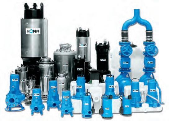

Submersible waste water pumps
Deep-well submersible pumps
Submersible sewage pumps
Submersible grinder pumps with cutter system
Waste water disposal units
Sewage disposal units
Packaged pump stations
Mixers
Injector systems for tank cleaning
Garden pumps and domestic booster units
Propeller pumps
Control boxes

HOMA pumps and systems are employed in over 100 countries worldwide – in a myriad of projects, large and small, including the Palm Islands in Dubai. They meet all international safety and production standards and are certified by the relevant state or private bodies for waste water disposal. It is one of our main objectives to maintain and extend this high standard at all times.
HOMA stays close to its customers through a comprehensive network of professional sales and service agencies.
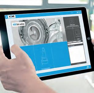
HOMA also makes selecting and designing pump systems as straightforward as possible through HOP.SEL, our specially developed software, available free of charge online.
HOMA Pumpenfabrik GmbH
Industriestraße 1 53819 Neunkirchen-Seelscheid, Germany

Telefon: +49(0)2247/702-0
e-Mail: info@homa-pumpen.de Internet: www.homa-pumps.com