27 minute read
Instruments and Controls


This chapter describes the instruments, panels and controls Volvo Penta sells for your engine. If you would like to complement your instrumentation, or if your boat is equipped with instruments not described here, we ask that you contact your Volvo Penta dealer.
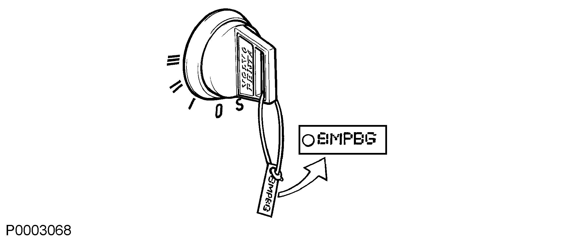
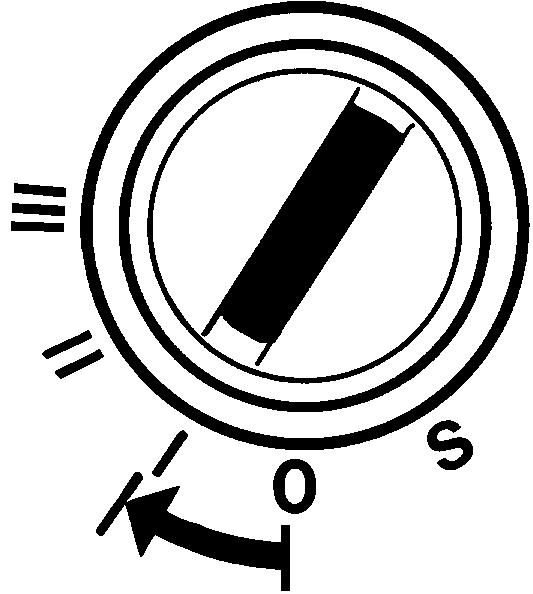
Ignition Lock
The start keys are supplied with a plate bearing the start code to be used when ordering spare keys. Keep the code beyond the reach of unauthorized people.
S = The stop position.
0 = The key can be inserted or removed.
I = Operating position. System power is connected.
II = Not used.
III = Start position. Starter motor is engaged.
There is always a main helm station on a boat. It is the only helm station with an ignition lock. The ignition must be switched on here in order for other helm stations to be used.
Read the starting instructions in the Starting page 45 chapter to make sure you use the correct start procedure.
Control Panels
Volvo Penta panels and gauges can be installed in different combinations. There is always one information panel per driveline and helm station if no 7" screen is installed. The control panels can be used together with the tachometer and other accessory equipment.
Information Panel
The information panel shows engine and operational information, messages and alarms. There is one information panel per driveline and helm station if no 7" screen is installed.
The information shown can be set up according to personal preferences. Basic settings show:
• Engine speed
• Oil pressure
• Coolant temp
• Battery voltage
Return to the previous menu by pressing the button. Hold the button down for more that 3 seconds to reach the main menu or browse back to it by pressing the button repeatedly.
Browse backwards and forwards through the information panel menus by pressing the buttons. Hold down a button to scroll through a menu.
Confirm a selection by pressing the button.
Settings
Browse to the settings menu and press “OK” to proceed to the submenu.
For further information about settings, refer to Settings Menu page 109
To adapt information shown in the main menu to suit your personal preferences, refer to My View page 109.
Fault messages
If the system discovers a fault, the word Fault is displayedonthescreen.Toseethewhatfaultshavebeen detected, press “OK”.
For further information on how to handle fault messages and recommended actions, refer to the Fault Handling page 56 chapter.
Backlighting
Panel backlighting can be adjusted by pressing simultaneously.
Start/Stop Panel
The start/stop panel is used for starting and stopping the engine frpm other stations than the main station.
To start the engine it is necessary for the start key at the main station to be in the ”I” operating position.
Read the starting instructions in chapter Starting page 45 and Engine Shutdown page 52 to ensure you use the correct start procedure.
Power Trim panel
The Power Trim panel allows you to adjust the angle of the drive with respect to the transom. For twin engine installations, the control panel can be used to make individual or simultaneous adjustments to the drives.
By trimming out the drive away from the transom, the bowwillbe”raised”inrelationtothehorizontalaxisand trimming in the drive will ”lower” the bow of the boat + Will trim the drive away from the transom, the bow will be ”raised” in relation to the horizontal axis. – Will trim the drive away towards the transom, ”lower” the bow of the boat.
For further information on Power Trim refer to Instruments and Controls page 32
Cruise Control
Switch on cruise control by pressing the button. Make fine adjustments to the locked engine speed by pressing the + or – buttons to increase or reduce it.
Station Panel
Activation
Activate the helm station with a single press of the button.
Further pressure locks the helm station. To render the helm station inactive, hold the button down for 3 seconds.
Inactive helm station
Active helm station
Locked helm station
Low speed and Power Trim Assistant (PTA) Depending on the installation the optional functions lowspeed or Power Trim Assistant are engaged with the button.
Low speed
For further information about the function, refer to Optional page 43.
Power Trim Assistant (PTA)
For further information about the function, refer to Instruments and Controls page 32
Neutral button
The gearshift function can be disconnected so that the control lever only operates the throttle. The neutral button disengages the drive/reverse gear so that engine speed may be increased without driving the boat; (warm-up mode).
The drive is disengaged.
Drive engaged for movement ahead/astern.
Single lever
When the single-lever function is activated, the lever thatismovedfromitspositionfirstbecomesthecontrol lever for both engines. The other control lever has no function as long as the single-lever function is activated.
Inordertoactivatethesingle-leverfunction,thecontrol levers must in be roughly the same position, max 10% difference.
Docking Panel
When the boat is operated from a docking station engines, can be stopped and started and messages can be managed using the docking panel. The joystick can be used for maneuvering when the docking station is activated; refer to the Joystick page 41 section for further information.
Activation
Activate the helm station by depressing the on/off button. A further pressure on the button locks the helm station.
To switch off the function, hold the button down for 3 seconds.
Twin instalation
Both engines in a twin instalation must be running before the docking station can be activated.
The helm station is inactive.
The helm station is active and the docking function is switched on.
The helm station is locked.
Start/Stop
Press the STOP and START buttons to stop and start all engines.
The circles above the engine symbols show which engines are running. An empty circle means an engine is running.
Contrast and backlighting
The button on the far right is used to adjust contrast and panel backlighting. The button is also used to confirm fault messages.
Backlighting Contrast
Press the button to adjust the contrast and the backlighting.
Use + and – to increase or reduce the contrast or backlighting.
Adjustments affect all screens in the system.
Fault message
is displayed on the screen when the system discovers a fault.
All fault messages must be acknowledged. Acknowledgebypressingthebutton;ifthefaultisaccompanied by an audible signal, the signal will silenced. Go to the information panel to get information regarding the alarm.
For further information on how to handle fault messages and recommended actions, refer to the Fault Handling page 56 and Fault Code Register chapters.
Gauges
These instruments are sold as engine options by Volvo Penta.
The tachometer displays engine speed; multiply the value shown on the dial by 1,000 to get the number of engine revolutions per minute. Engine hours is displayed in the tachometer window. When a function is activated a symbol shows shortly in the dispaly.
1 Fuel level gauge
The fuel level gauge shows the quantity of remaining fuel.
2 Voltmeter, battery charging
The meter shows the alternator charge current. During operations the charge voltage should be around 14 V. When the engine is stopped and electrical power switched on the battery voltage should be around 12 V.
3 Coolant temperature gauge
The instrument shows engine coolant temperature. During operations coolant temperature should normally be between 75-95°C (167-203°F).
4 Oil pressure gauge
The oil pressure gauge displays engine oil pressure. During operations the oil pressure gauge should normally show 3-6 bar. At idle, lower values are normal.
5 Fresh water level sensor
Freshwater tank level gauge.
6 Rudder position indicator
The instrument shows rudder position.
7 Trim indicator, analog, for Aquamatic engines
The analog indicator shows the position of the stern drive in relation to the transom shield.
8 Trim indicator, digital, for Aquamatic engines
The digital indicator shows the position of the stern drive in relation to the transom shield.
9 Alarm monitor
The alarm monitor gives a visual warning to call attention to any alarms that occur.
4" Screen
IMPORTANT!
Make a habit of protecting the screen with the protective cover when the boat is not in use. Prolonged exposure to strong sunlight can damage the screen and cause function faults.
The Volvo Penta 4" screen is controlled by means of buttons on the panel: Return to the previous menu by pressing the button.
P0001101 Press the button to adjust the display contrast. The image reverts automatically a short while after the button is released.
Menu button functions are shown on the display. Scroll back and forth or confirm a selection by pressing the appropriate button.
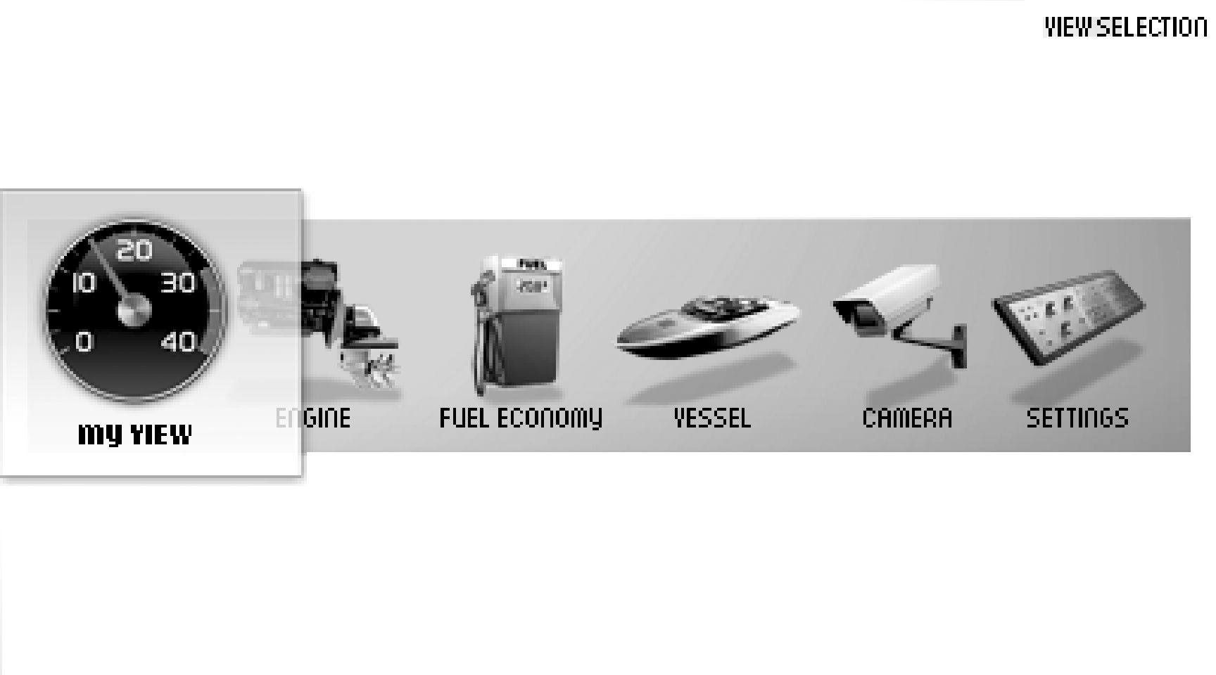
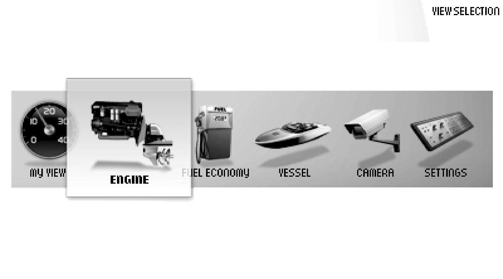
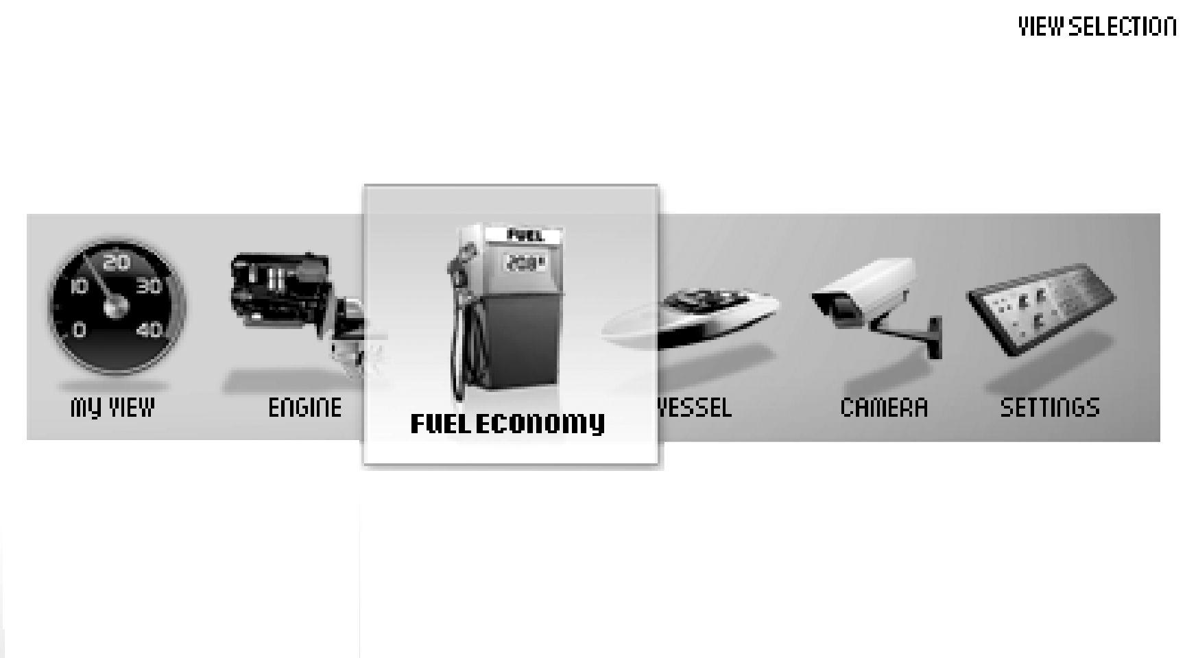
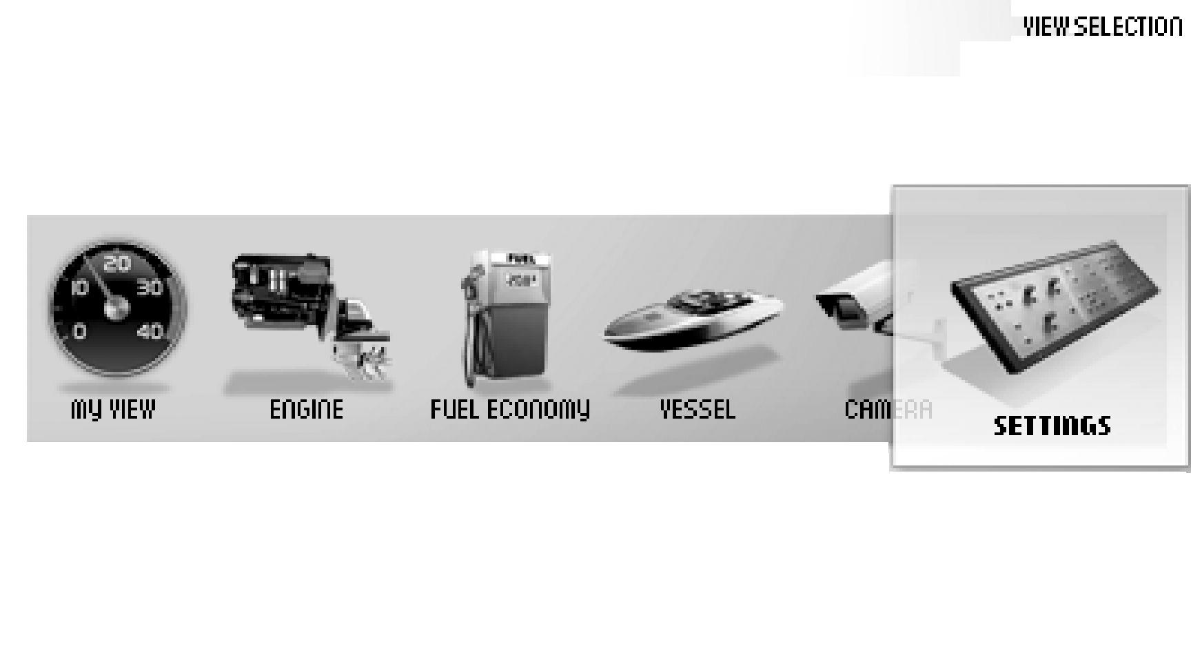
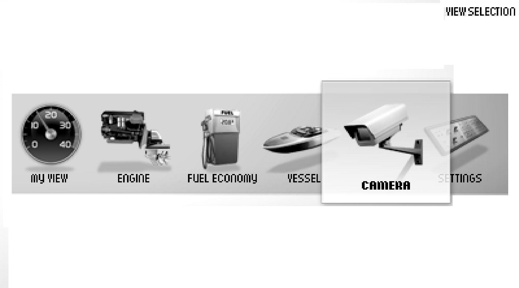
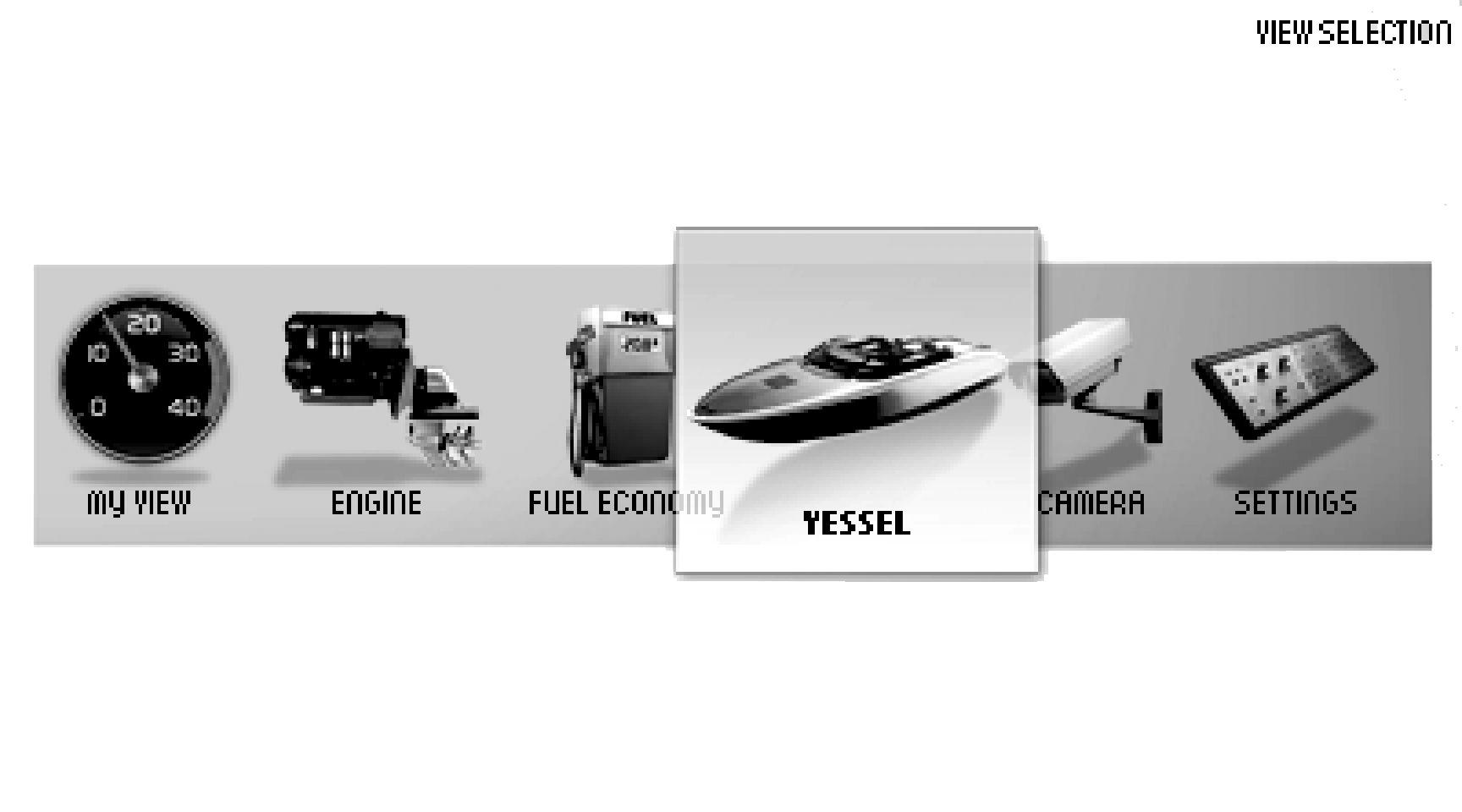
View Selection
The last selected view is shown on start. To return to the main menu, click . Navigate to the desired screen using the arrow buttons.
• My View Operating information
• Engine View Engine information
• Fuel economy Trip computer
• Vessel Information regarding the boat's installation
• Settings Settings, display and installed functions
• Warning Manager Shows system faults detected and describes remedial actions
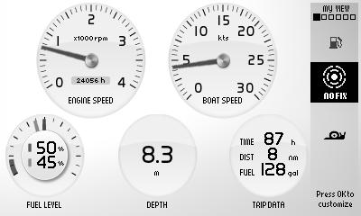
My View
Gauge and operations information is shown in the My View window.
Some functions are pre-set as quick selections. These can be switched on/off by pressing OK.
To change the gauge and information shown, refer to Change gauge. Functions are also switched on and off here.
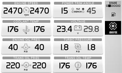
Engine View
Engine View
Informationconcerningtheengineanditstransmission is shown in Engine View. The information is shown in twowindows;switchbetweenthewindowsbypressing the arrow buttons.
Up to six different pieces of operations data can be shown on the display. The information shown can be set under Change gauge
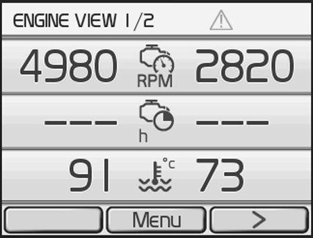
Depending on the functions installed in the boat, the following can be displayed:
Engine speed
Engine hours
Engine Coolant Temperature
Battery Voltage
Engine oil pressure
Turbo pressure
Exhaust Temperature
Transmission Oil Pressure
Transmission oil temperature
Propeller Rotation
Ahead speed
Power Trim angle
Average fuel
Fuel
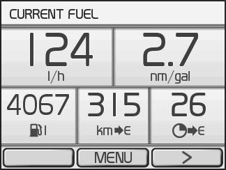
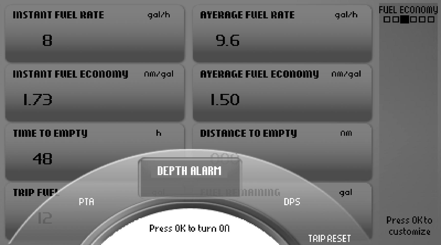
This is the boat's trip computer and information is shown in two windows, Current Fuel and Average fuel. Switch between screens by pressing the arrow buttons.
Current Fuel
• Instant fuel rateCurrent fuel consumption per hour.
• Instant fuel economy Based on current fuel consumption.
• Remaining in tank Amount of fuel remaining in the tank.
• Distance remaining Trip distance with fuel remaining in the tank based on current fuel consumption.
• Time to empty Operating time with fuel remaining in the tank based on current fuel consumption.
Average fuel
• Average fuel rate Average fuel consumption since the last trip computer zero reset.
• Average fuel economy Average since the last trip computer zero reset.
• Trip distance Average fuel consumption per unit of distance since the last trip computer zero reset.
• Trip fuel, fuel consumption per unit since the last trip computer zero reset.
• Trip hours Time travelled since the last trip computer zero reset.
Vessel
Trip Computer Reset
Tozeroallvaluesinthetripcomputer,presstheMENU button and select Trip Reset.
Settings
Vessel
Shows information regarding the boat's installation. The information shown can be set under Change gauge. Functions are also switched on and off here. Depending on the functions installed in the boat, the following can be displayed:
• Boat Speed
• Rudder angle
• Depth for setting echo sounder; refer to Depth Alarm page 110.
• Fuel level
• Sea water temperature
• Freshwater level
• ACP Info for further ACP information, refer to the ACP chapter.
Settings
Display and various system function settings are done in the settings menu. The information shown varies depending on the installation. Navigate to the desired setting or function and press to reach the sub menu.
Day/Night-Mode
Day shows dark text against a light background and Night light text against a dark background.
Fuel Tank
Fuel tank calibration and settings. For information regarding calibration, refer to Fuel Tank page 115
Drive Type
The setting may only be made by authorized Volvo Penta personnel.
Toe-In/Toe-Out Adjustment
The setting may only be made by authorized Volvo Penta personnel.
Neutral Beep
Switches the beeper that sounds when the control is in the neutral position on and off.
Info Beep
Switches the signal that confirms when a function has been activated or deactivated on and off.
Info Beep level
Sets the volume (%) of the Info Beep that confirms when a function has been activated, or deactivated.
PTA Calibration
Calibration and resetting, PTA. For information regarding calibration, refer to PTA Calibration page 114.
Trip Reset
Zeroes all values in the trip computer.
ACP Mode
Setting the ACP protection position. For information on the ACP function, refer to ACP
Depth Alarm
Setting the depth alarm function; refer to Depth Alarm page 110
Display Contrast
Contrast adjustments affect all displays in the system.
Display Type
Select the engines for which the information will be shown in the display, and the type of installation the display forms part of.
Units
Setting the units (metric, US or Imperial) and distance units (km, NM or miles) distances will be shown in.
Language
Setting the language information will be shown in.
Speed Factor
Setting the velocity factor; refer to Speed Factor page 116
EVC Information
Informationaboutcomponents,softwareandfunctions installed. Installed functions are checkmarked.
Replace gauge
Warning Manager
If the system discovers a fault, the helmsman is informed by a message on the display. The fault message must be acknowledged by pressing OK. All fault messages are stored in Warning Manager; the drivetrain affected is shown, the fault described and suitable actions suggested. For further information on different fault messages, refer to the Fault Code Register page 59
Replace gauge
In My View, Engine View and Vessel the owner can decide what information will be shown and where on the display. The procedure is the same for all views.
1 Press the MENU button and select Replace gauge.
2 Navigate using to the gauge for replacement and press
3 Select the gauge for replacement and press
Restore Default View
The display has a basic setting that it is always possible to return to.
1 Press the MENU button and select Restore Default View.
2 Press
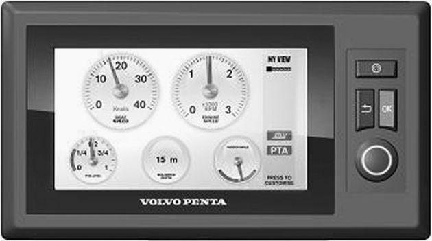
7" screen
The Volvo Penta 7" screen is controlled by means of buttons:
Turntobrowsethroughsubmenusandtoreturn to the main menu.
Return to the previous menu.
OK Confirms selection; also used to access submenus and the Settings page 29
P0001101 Controls boat instrument backlighting. The page automatically returns a few seconds after the button is released.
IMPORTANT!
Make a habit of protecting the screen with the protective cover when the boat is not in use. Prolonged exposure to strong sunlight can damage the screen and cause function faults.
The status field (2) on the right of the screen displays the current view, active functions and repaired faults.
Pop-up
A number of pre-set functions can be switched on and off in a pop-up. Press OK and the functions will show in the lower part of the screen (1).
Turn to the desired function and press OK to confirm that the function is to be switched on or off. Active functions are displayed by a symbol in he status field (2) on the right.
Trip Reset is also found here; refer to Fuel economy page 28.
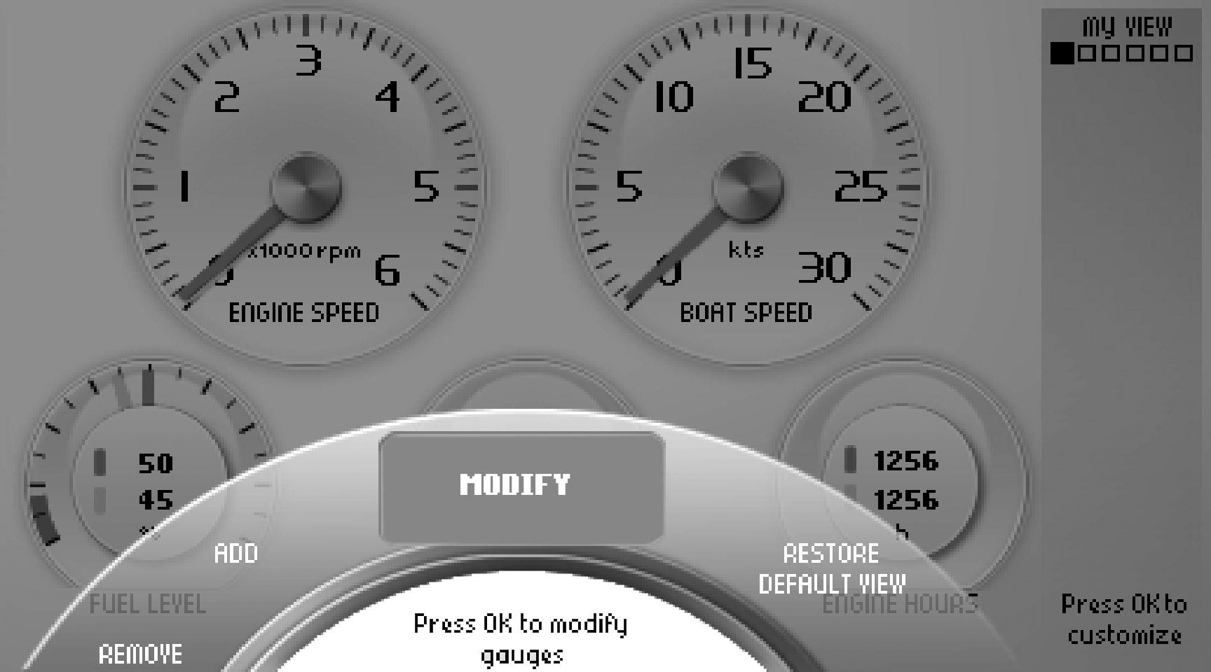
My View
Boat, engine and transmission data are displayed in My View as analog or digital instruments. Selection of instruments to be displayed and their appearance is made under the Customize menu. Information for up to three engines can be displayed onthesamescreeninboatswithmultipleengineinstallations; they are distinguished by different color dials in the instruments.
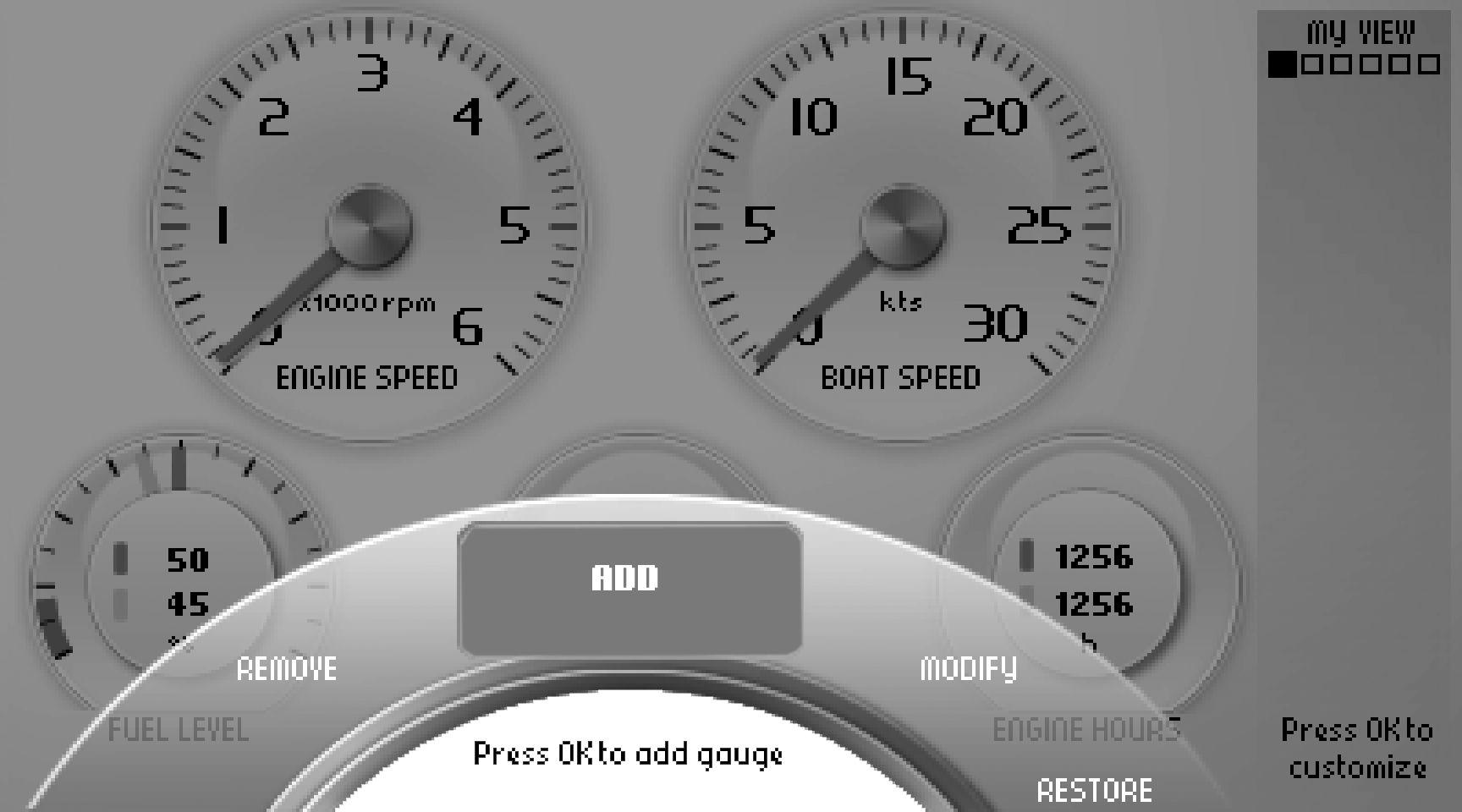
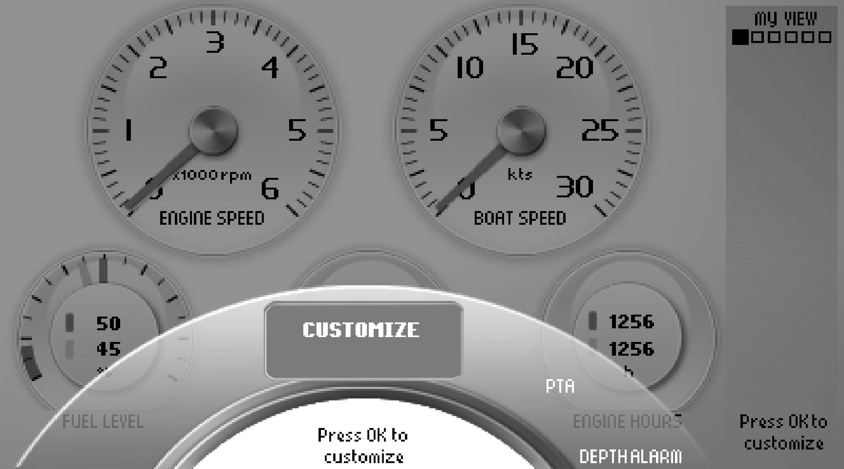
Customize
Press OK so that the Customize menu is displayed. Press OK to access the submenus Add, Remove, Modify and Return to basic setting. Use the knob to browse between menus.
Adding instruments
Turn the knob to Add and press OK Selectthedesiredinformationisdisplayedandconfirm with OK . The new instrument will position itself at the bottom right corner.
Removing instruments
Turn to the Remove menu and press OK
Turn to the instrument that is to be removed and confirm with OK .
Changing instruments
Turn to the Modify menu and press OK
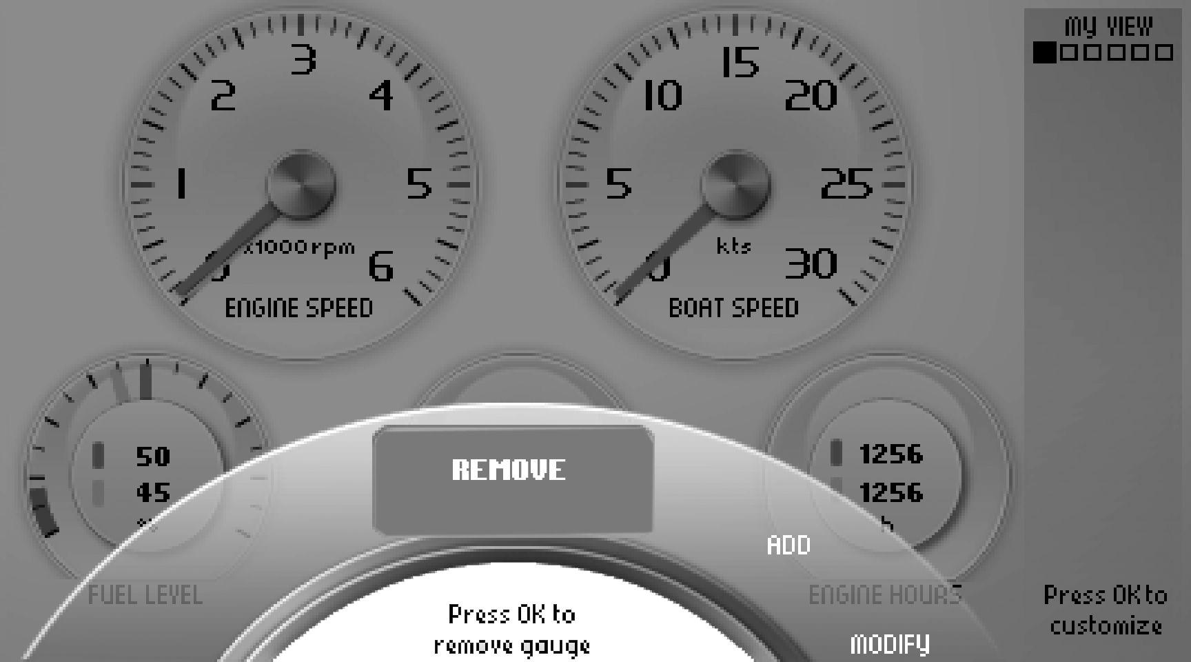
Select the instrument that is to be changed and press OK
Choose between: Remove, removes the instrument. Replace, changes one instrument for another. Turn to the desired instrument and press OK
Analogue/Numeric, specify whether the instrument will be displayed as analog or digital.
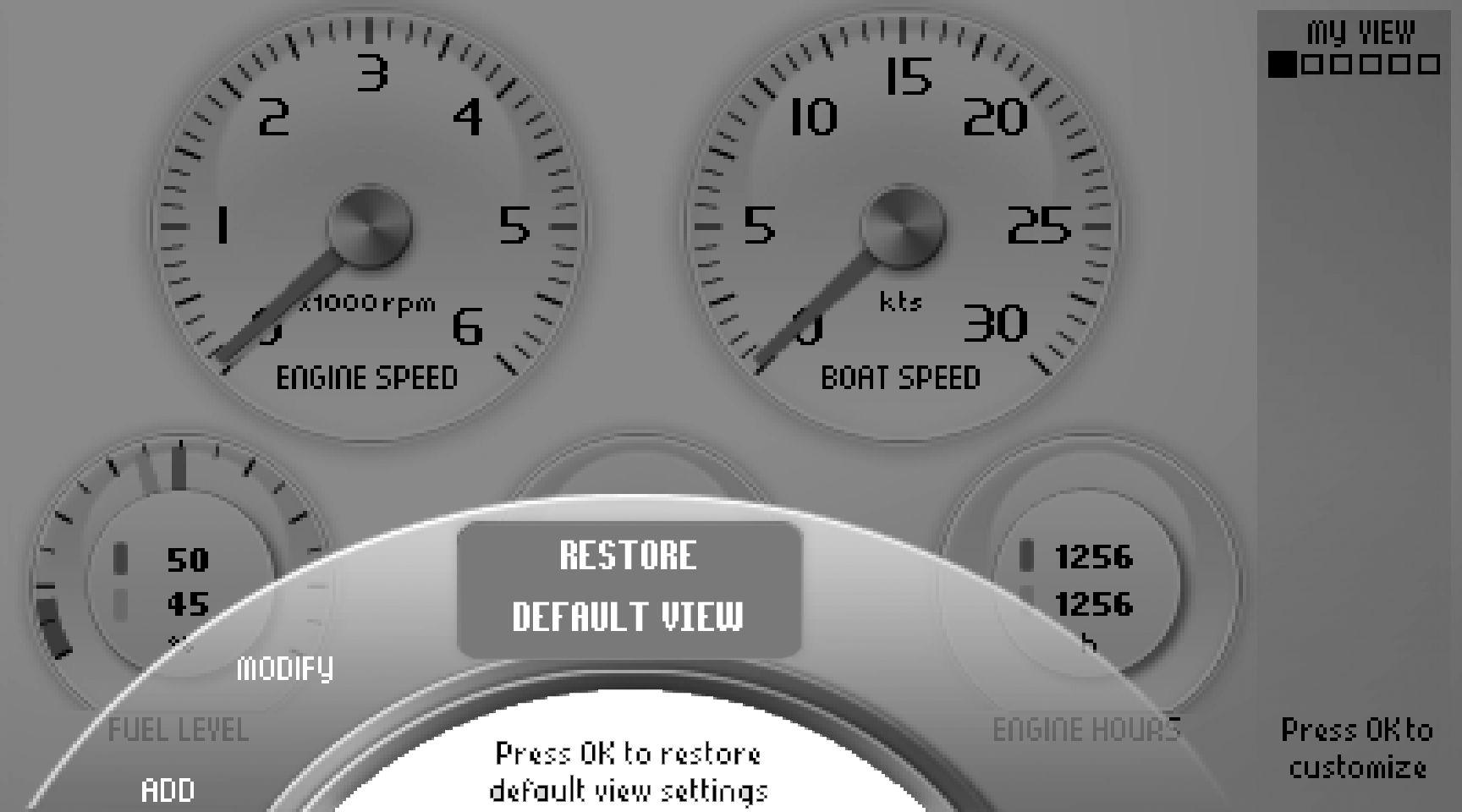
Restore Default View
The screen has a basic setting that can always be returned to by pressing Restore Default View in the Customize menu.
Engine
Informationconcerningtheengineanditstransmission is displayed in this view.
Depending on the functions installed in the boat, the following can be displayed:
- Engine Speed
- Power Trim angle, for further information refer to Trim Controls and PTA calibration in the Settings Menu page 109 chapter.
- Rudder angle
- Coolant Temperature
- Voltage, battery voltage
- Engine oil pressure
- Turbo pressure
- Engine hours, total operating hours.
The information in this view cannot be changed.
Fuel economy
This view functions as the boat's trip computer.
Depending on the functions installed in the boat, the following can be displayed:
Current Fuel
Instant fuel rate, based on current fuel consumption
Instant fuel economy, current fuel consumption per hour.
To Go
Distance remaining, trip distance with fuel remaining in the tank based on current fuel consumption. Time to empty, operating time with fuel remaining in the tank based on current fuel consumption.
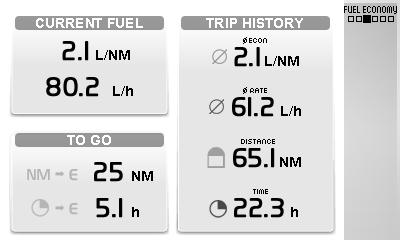
Trip History
Average fuel rate, average fuel consumption since the last trip computer zero reset.
Average fuel economy, average since the last trip computer zero reset.
Trip distance, distance travelled since the last trip computer zero rest.
TripTime,timetravelledsincethelasttripcomputer zero rest.
To zero all values in the trip computer press OK
The information in this view cannot be changed.
Vessel
Information concerning boat installations is displayed in this view.
Depending on the functions installed in the boat, the following can be displayed:
- Sea water temperature
- Depth, to set the echo sounder refer to Depth Alarm in the Settings Menu page 109 chapter.
- Boat Speed
- Rudder angle
- Fuel level
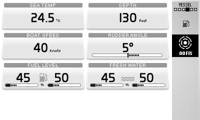
- Freshwater level
- ACP Info, for further ACP information, refer to the ACP chapter.
The information in this view cannot be changed.
Camera
It is possible to connect a camera to the screen (e.g. for monitoring the engine compartment or swimming platform).
If a camera is installed, images will be displayed in this view.
Settings
Screen settings and different function settings are made in this view. Turn to the desired menu and press OK to access the submenus.
Mode
Choose between the modes Day ((dark text on a white background)orNight(lighttextonadarkbackground). Press OK switch between modes.
Background
Choose between the background colors Gray, Aqua, White, Carbon and Red.
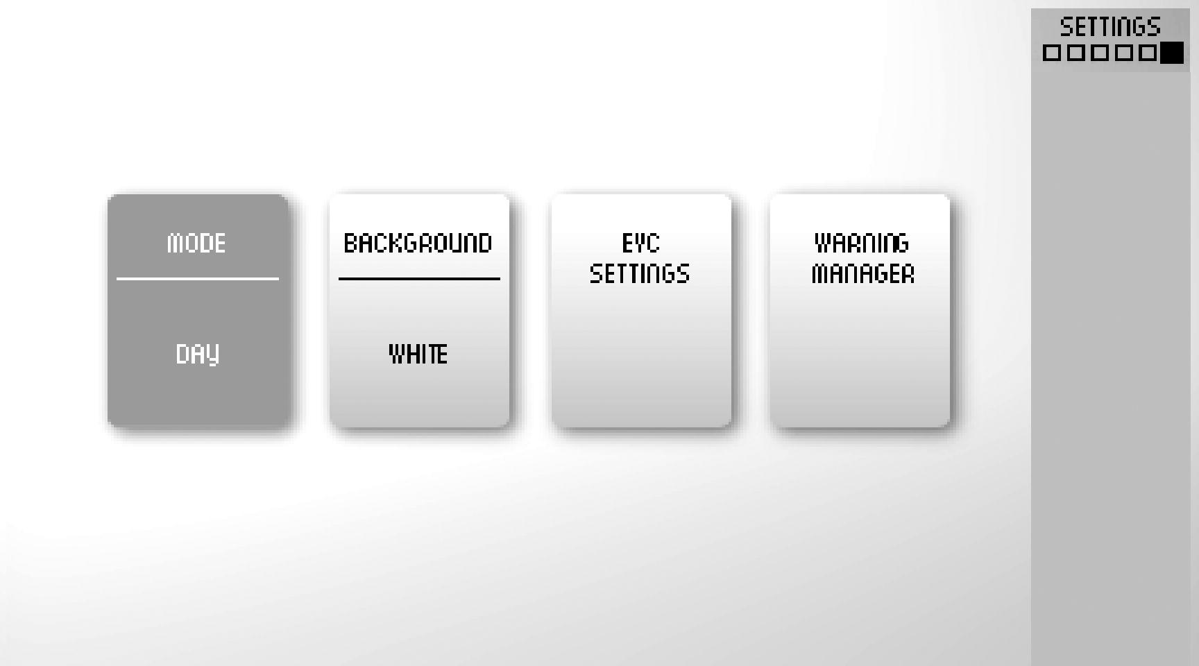
EVC Settings
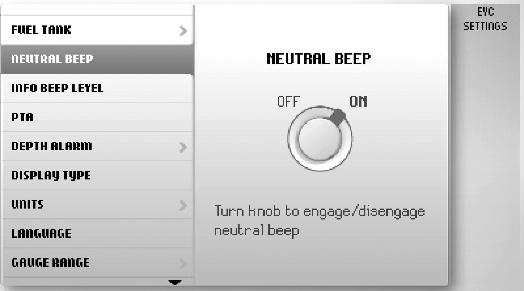
Press OK to access the settings menu. Settings for screen, switching functions on and off, audible alarm settings, alarm limits, language and units. Information regarding boat installations is also found here.
Neutral Beep, switching on and off the beeper that sounds when the control is in the neutral position.
Info Beep Level, setting the volume of the signal that confirms when a function has been activated or deactivated.
Trip Computer Reset, zeroes all values in the trip computer.
Camera, choose to reverse image or show camera at dockingstation.
Display Type, select the engines for which operating data will be displayed and the type of installation the engines is part of.
Infodisplay Contrast justera kontrasten i samtliga skärmar på stationen.
Units, setting of units (metric/U.S.) and distance (km. Nm. or miles).
Language, selecting the screen language.
Gauge Range, setting instrument maximum display range.
Boat Speed, 10 – 100 in steps of 10 knots. Engine Speed, 2500/3000/4000/5000/6000 r/min. Propeller speed, 1000/2000/3000 r/min.
EVCInformation,thisinformationcannotbechanged. Features, installed functions are marked blue. Components, press OK to see installed components.
Software, information regarding the software ID number.
Calibration
The following is only displayed if the function is installed. For further information, refer to the relevant sections in theSettings Menu page 109 chapter.
Speed Correction, setting the speed factor.
Depth, setting the echo sounder depth alarm. Follow the instructions on the screen.
Fuel Tank, fuel tank calibration. Follow the instructions on the screen.
ACP Info, setting the ACP protection position. PTA, PTA calibration. Follow the instructions on the screen.
Warning Manager
If the system discovers a fault, the operator is informed by a message on the screen. The fault message must be confirmed by pressing OK
All faults are stored in the Warning Manager
The fault message indicates the drivetrain affected, describes the fault and suggests suitable actions..
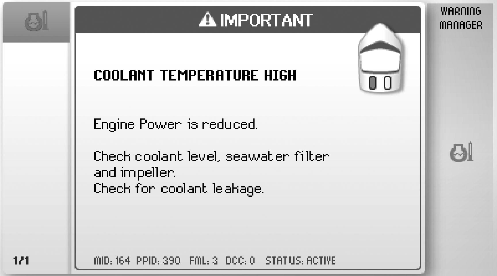
For further information on fault messages, refer to Fault Handling page 56
1Symbol
2Shows on which drive line the fault is detected.
3List of registered faults; turn the knob to browse.
4Fault message with description and suggestion for action.
5Service information.
Power Trim
Your Volvo Penta drive is equipped with a hydraulic trim system, Power Trim, that allows you to adjust the angle of the drive with respect to the transom from the helm station. The angle of the drive effects the boat's passage through the water and other characteristics, e.g. improved acceleration to planing and planing with a lower throttle opening. Trimming can also be used to give a more gentle passage in short seas.
Running on one engine in twin installations
If only one engine is working, the drive for the engine that is not running must be raised. To raise the engine:
1Turn the key for the drive that will not start to the run position so that system power is connected and the engine is stopped.
2Using the trim button, raise the drive as high as it will go.
3Turn the key to the stop position.
IMPORTANT!
Failure to raise a faulty drive in a twin installation with one engine running can result in the drives' colliding with each other and suffering damage.
Trim Ranges
To be able to use the information on the trim instrument, it is important to be aware of the three trim ranges and the way they are used.
Trim range
The trim range are used to provide the best comfort when driving – from starting to top speed.
Beach range
The beach range is used for driving at low speed in shallow water or where the depth is unknown. Thehighestpermittedenginespeedwheninthebeach range is 1500 rpm.
IMPORTANT!
Makesurethedrive'scoolantinletisnevertrimmedout of the water when operating in the beach range.
Lift range
The lift range is never used when sailing. It lifts the drive to maximum height and is used for e.g. transporting the boat on a trailer. Power Trim has an automatic stop that turns off the power when the end position is reached. The catch is released automatically when the stern drive is trimmed down.
WARNING!
The engine must not be run with the drive in the “lift” range.
Trim Controls
The drive can be trimmed with the Power Trim panel or with the button at the side of the control (1). For twin engine installations, the button at the side adjust the drives simultaneous. There is also a button for individuall adjustments to the drives (2) on the control for twin installations.
Power Trim panel
The Power Trim panel is used for both single and twin engine installations. For twin engine installations, the control panel can be used to make individual or simultaneous adjustments to the drives.
The drive's angle and position is shown on the Power Trim panel. By trimming out the drive away from the transom the bow will be ”raised” in relation to the horizontal axis and trimming in the drive will ”lower” the bow of the boat.
Trimming out the drive
On the Power Trim panel, press button + to trim the drive out, away from the transom. The bow will be ”raised” in relation to the horizontal axis.
Trimming in the drive
Pressbutton–totrimthedrivein,towardsthetransom. The bow will be ”lowered” in relation to the horizontal axis.
Power Trim Assistant
The Power Trim Assistant, PTA, adjusts the trim angel automatically according to engine speed (rpm). It is possible to set five trim angles at five different engine speeds, idle speed included. To set the angles, please refer to PTA Calibration page 114 is shown on the screen if the PTA function is active.
Press the PTA button on the helm station panel or the Trim Assist button on the control to activate or de-activate the function.
Trim Instruments WARNING!
The engine must not be run with the drive in the “lift” range.
Digital trim instrument
The trim instrument shows the drive trim setting. The angleofthedriveisgiveninrelationtoahorizontalline. The lowest value indicates that the drive is fully trimmed down and the highest value that the drive is fully trimmed up. Note that the lowest value can vary from boat to boat, depending on the angle of the transom. When the drive angle is within the trim range, the text ”TRIM” is shown on the display. When the drive angle is within the beach range, lamp 1 lights orange and the text “BEACH” is shown on the display.
When the drive is in the lift range, the drive angle is greater than +30° and lamp 2 lights red. There is no text on the display.
Analog trim instrument
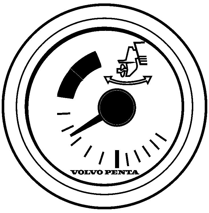
The trim instrument shows the drive trim setting. The beach range is marked with an orange zone and the lift range with a red zone.
1Trim ranges
2Beach range (orange)
3Lift range (red)
Maneuvering
Thecorrecttrimsettingprovidesthebestcomfortwhen driving.
Every boat has its own unique characteristics and reacts differently to how you trim it. We can therefore only give general advice about how you reach the best trim angle for your boat. It can generally be said that when the boat feels well balanced, is easy to steer and comfortabletodrive-thanyouhavefoundtheoptimum trim angle.
Make a few trips at low speed to experience the effect of Power Trim and the different trim ranges, to see what effect they have on the boat. Note how long it takes for the boat to reach planing speed. Check the tachometer, speed and the response of the boat.
Trim the drive down
The bows are pressed down and the boat accelerates faster. It also provides better driving and steering response at speeds below the planing threshold.
Driving with ”bow down”
The”bowdown”positionisnormallyusedduringacceleration up to planing speed, at low planing speeds or with a short sea. With full ”bow down”, the boat has a tendency to self-steer. You may have to compensate with the wheel to keep the boat on the right course. In this position, the bow of the boat tries to go deeper in the water. If the boat is driven at high speed or towards high waves, the bow will plough downwards into the water. The boat can start to steer with the bows or yaw suddenly so that passengers may be thrown overboard.
The boat's trim shall always be adjusted to give well balanced steering. Certain combinations of boat, engine and propeller can cause instability and/or selfsteering tendencies when the boat is driven at or close tothemaximum”bowup”or”bowdown”positions.The stability and steering characteristics of the boat can also vary depending on the sea conditions. Contact your Volvo Penta dealer to correct these tendencies if your boat shows instability an/or self-steering tendencies.
At planing speed
Trim the drive to the angle that gives the most stable and comfortable feeling. If the boat has a twin installation, the drive can be trimmed to different angles to compensate for side winds and, to a certain degree, uneven load distribution.
Driving with ”bow down”
The ”bow up” position is normally used for driving at cruising speed, in short seas, or at full speed. With full”bowup”theboatcanhaveatendencytoself-steer. You may have to compensate with the rudder to keep the boat on the right course. In this position, the bow of the boat tries to lift out of the water. Excessive ”bow up” trim causes propeller cavitation, so that the propellerloosesitsgrip.Theenginespeedincreaseswithout the boat speed increasing, in fact the boat might even sink.
Be careful when driving in short seas. Excessive ”bow up” trim may cause the boat to bounce quickly upwards, with the risk of throwing passengers overboard.
In short seas or heavy head seas
Trim the drive down so that the bow drops. This makes for a more comfortable journey. Refer to section Driving with "bow down"
Driving in Beach range
The beach range is used for driving at reduced speed in shallow water or where the depth is unknown. ThehighestpermittedenginespeedwhenintheBeach range is 1500 rpm.
IMPORTANT!
Makesurethedrive'scoolantinletisnevertrimmedout of the water when operating in the beach range..
Controls
This section describes the controls Volvo Penta sells for your engine. Contact your dealer if your boat is equipped with controls other than those described here, and you feel uncertain about their function.
A single-lever control operates both gearshift and throttle functions with the same lever. The engine can only be started with the control lever in the neutral position.
N = Neutral position. Reverse gear/drive disengagedand engine at idle.
F = Reverse gear/drive engaged for forward motion.
R = Reverse gear/drive engaged for rearward motion.
T = Engine rpm control (throttle).
Engine and drive features are controlled with push buttons on the control. What buttons and functions available is depending on the installation.
1STATION
Thebuttonlampislitifthehelmstationisactiveand lit. Refer to Helm Stations page 50 for further information.
2CRUISE CONTROL (optional)
Switch on cruise control by pressing the button. Fine tune the locked engine speed by increasing (+) or reducing (-) engine rpm with the button at the other side of the control.
3LOW SPEED (optional)
See Optional page 43 for information.
4THROTTLE ONLY
Disconnects the shift function so that the control lever only affects engine speed; refer to "Disengaging shift function" in this chapter for further information.
5SINGLE LEVER (optional)
Switch on the single-lever function by pressing the button. The lever that is moved from its position first becomes the control lever for both engines. The other control lever has no function as long as the single-lever function is activated. The button lamp lights up to show that the function is active. Exit the single-lever function by pressing the button again.
7
Neutral position. The symbol shows that the drive/ reverse gear is disengaged.
The warning triangle lights up if the system discovers a fault; refer to Fault Handling page 56 for information.
The warning triangle lights up on the same side as the driveline with the indicated fault.
8This function is not available.
9TRIM ASSIST
The Power Trim Assistant, PTA, adjusts the trim angel automatically according to engine speed (rpm), see Power Trim Assistant page 34 for information.
10TRIM
Trim the drive out//in.
For twin engine installations the adjustment of the drives are synchronized. For further information see Instruments and Controls page 32
Side-mounted control
1TRIM
Trim the drive out//in. For twin engine installations the adjustment of the drives are synchronized. For further information on Power Trim see Instruments and Controls page 32.
2
Neutral position. The symbol shows that the drive/ reverse gear is disengaged.
The warning triangle lights up if the system discovers a fault; refer to Fault Handling page 56 for information.
This function is not available.
3+ / -
Fine tune the locked engine speed for tow mode (4)orcruisecontrol(5)byincreasing(+)orreducing (-) engine rpm.
4TOW MODE
Accelerates the boat to a preset rpm. Switch on toe mode by pressing the button. Finetunethelockedenginespeedbyincreasing(+) or reducing (-) engine rpm with button (3).
5CRUISE CONTROL (optional)
Switch on cruise control by pressing the button. Finetunethelockedenginespeedbyincreasing(+) or reducing (-) engine rpm with button (3).
6TRIM ASSIST (optional)
The Power Trim Assistant, PTA, adjusts the trim angel automatically according to engine speed (rpm), see Power Trim Assistant page 34 for information.
7THROTTLE ONLY
Disconnects the shift function so that the control lever only affects engine speed; refer to "Disengaging shift function" in this chapter for further information.
8Neutral interlock
The neutral interlock prevents acidentally moving the throttle out of neutral. Depress the interlock button to move control out of neutral.
The neutral interlock will automatically re-engage when the control handle is returned to the neutral position.
Disengaging the Shift Function
The gearshift function can be disconnected so that the control lever only operates the throttle.
1Put the control levers in neutral.
2 Press the control “Throttle Only” button or the neutral button (N) on the helm station panel.
3Release the button. The N symbol on the control will light up as confirmation that the gearshift function is disengaged and that the lever will only affect engine revolutions.
To exit neutral mode, press the button again.
Adjusting the friction brake
Top mounted controls
The control lever has a friction brake that can be adjusted for lighter or stiffer lever movement. Resistance in click mode can also be adjusted.
1Switch off the engine.
2Remove the cover (3).
3 Adjust the friction brake (1) and/or click mode (2) by turning the screw clockwise for stiffer lever movement, and counterclockwise for lighter lever movement.
4Replace the cover.
Side-mounted control
Adjust the resistance in the lever click mode.
1Switch off the engine.
2Unscrew the screw (1) and remove the cover (2).
3 Adjust the detention by turning the screw (3) with a 2.5 mm hex wrench. Turn the screw clockwise for an increased detent , and counterclockwise to decrease the detent.
4Replace the cover.
P0008840
Joystick
The Volvo Penta Joystick is a control used for docking and maneuvering at low speed.
Learn to use the joystick and its functions in a safe and proper manner before beginning to use the function in confined marinas.
Maneuvering with the joystick
The boat is maneuvered by moving the joystick forward, aft, abeam or by twisting the top of the joystick; see illustration..
IMPORTANT!
The boat will continue to move in the selected direction even when the joystick has been released; compensate for this by moving the joystick in the opposite direction.
Docking
When the docking function is activated, engine revolutions are limited and the boat can only be steered by the joystick.
In order to activate the docking function, the following must be fulfilled:
• engines running
• control levers in neutral
• helm station active
• joystick in center position
Activating the docking function
Activate docking mode by depressing the docking button (A) on the joystick.
An audible signal will confirm that docking mode is activated and the docking button lamp will light up.
Exiting the docking function
To exit the function, press the joystick docking button (A). An audible signal will sound twice to confirm that docking mode is deactivated, and the docking light will go out.
The docking function is also deactivated if the controls are moved from the neutral position.
High Mode
If extra power, e.g. when there is a strong wind or strong current, the High Mode function may be engaged.
Activate High Mode
Activate the High Mode function by depressing button (B) on the joy stick.
Anaudiblesignalconfirmsthatthefunctionisactivated and the high Mode button lights up.
Disengage High Model
Disengage the function by pressing the button again. An audible signal will sound twice to confirm that docking mode is deactivated, and the light will go out. The system is now in normal docking mode.
A P0012499
R F N A
Low speed
The Volvo Penta low speed function is available for engines with hydraulic transmissions. Boats with powerful engines can have high speeds even at low revolutions; the low speed function reduces speed.
N = Neutral position.
Transmission is disengaged and engine revolutions are at idle.
F = Forward at idle.
The transmission is engaged for operations ahead and the engine is at idle; this involves maximum trolling in the transmission.
R = Reverse at idle.
The transmission is engaged for operations astern and the engine is at idle; this involves maximum trolling in the transmission.
A = Low speed engaged.
The transmission affects propeller revolutions. The engine is not affected.
B = Low speed disengaged.
B B 47701352 04-2011 43
Engaging the low speed function
1Move the lever to the neutral position.
2 Press the Low Speed button on the control or on the helm station panel to activate the low speed function.
Anaudiblesignalandthemessage“Lowspeedactivated” (A) will be displayed on screen to confirm that the function is on.
is shown on the screen if the low speed function is active (B).
When the low speed function is engaged a delay may occur when shifting.
Disengage the low speed function
1Move the lever to the neutral position.
2Press the Low Speed button on the control or on the helm station panel to disengage the low speed function.
Two audible signals confirm that the function is switched off and the “Lowspeed deactivated” (C)message is displayed on the screen.
Starting
Make a habit of visually checking the engine, engine bay and transmission before start. This will help you to discover quickly if anything abnormal has happened, or is about to happen. Also check that instruments and warning displays show normal values when you have started the engine. To minimize cold start smoke we recommend the installation of an engine heater or engine bay heater if temperatures below +5°C (41°F) are encountered.
WARNING!
Never use start spray or similar products as starting aid. Explosion risk!
Before Starting
• Check the engine and transmission oil level.
• Check the coolant level.

• Open the sea cock where fitted.
• Open the fuel cock.
• Turn the main switch(es) on.
IMPORTANT!
Never disconnect the current with the main switches when the engine is running. The alternator and electronics could be damaged.
• Start the engine bay fan, where fitted, and allow it to run for at least four minutes.
• Checkthatthereissufficientfuelfortheplannedtrip.
• Lower the stern drive if it is up.
Starting the Engine
Shifting and adjusting speed is only possible at an active station.
On a boat with one station the station is always active. On a boat with two or more stations the main station automatically becomes active when the engine is started up with the ignition key(s). If the engine(s) is/ are started from another station this station automatically becomes active instead.
Put the reverse gear in neutral
Put the drive in neutral by moving the control lever(s) to neutral at all stations.
Two lever control: Also check that the engine speed lever is in the idling position.
Turn the ignition on
Turn the starter key to position. I to switch the ignition on.
Check the information display
If a fault is registered it will be shown in the information display, please refer to Fault Handling page 56 for further information and recommended actions.
Start the engine
If a station is locked the engines can only be started and stopped from this station.
Start using the ignition switch
Start using the ignition switch III. Release the key and let it spring back to position I as soon as the engine has started.
If repeated start attempts are needed, the key must be turned back to position 0 first.
Stop cranking if the engine does not start within 20 seconds.
Starting with the starter button
Press the starter button for each engine. Release the button as soon as the engine has started.
If you start from a secondary station, the starter key at the main control station must be in position I Stop cranking if the engine does not start within 20 seconds.
Overheating protection
If the starter motor is engaged for its maximum activation time (30 seconds), the starter motor circuit is cut automatically to protect the starter motor from overheating. If possible, leave the starter motor to cool for atleastfiveminutesbeforemakinganewstartattempt.
Read the instruments and warm the engine up
Allow the engines to idle for the first ten seconds. Check that instruments and warning displays show normal values.
Checkthatnomessagesaredisplayedandnowarning signs are showing. If a fault is registred, please refer to section Fault Handling page 56 for further information and recomended actions.
Warm the engine up at low speed and low load, so normal operating temperature is reached before full power is used.
IMPORTANT!
Never race the engine when it is cold.


