19 minute read
Freshwater System


The freshwater system is the engine's internal cooling system that ensures that the engine operates at the correct temperature. It is a closed system that must always be filled with a coolant mixture in order to protect the engine against internal corrosion, cavitation and frost bursting.
IMPORTANT!
Coolant of a suitable chemical composition must be used all year round. This applies even when there is no risk for frost damage, so that the engine always has complete corrosion protection.
The use of anti-corrosion agents alone is not permitted in Volvo Penta engines. Never use water alone as the coolant.
The corrosion protection additives become less effective over time, which means that the coolant must be changed at regular intervals; refer to Maintenance Schedule page 67. The cooling system must be flushed whenever the coolant is changed, refer to Freshwater system, Flushing
Volvo Penta recommend ”Volvo Penta Coolant VCS, ReadyMixed”ortheconcentrate”VolvoPentaCoolant VCS” mixed with pure water according to specifications, see Water Quality
Volvo Penta Coolant VCS and VCS Ready Mixed are based on organic acid technology (OAT). Using other types of coolant, such as conventional or hybrid types, can drastically reduce the heat transfer and result in overheating of the engine.
Coolant, Mixing
WARNING!
All coolant is hazardous and harmful to the environment. Do not consume. Coolant is flammable.
IMPORTANT!
Different types of coolant must not be mixed with each other!
Mix: 40% “Volvo Penta Coolant” (conc. coolant)and 60% water
This mixture protects against internal corrosion, cavitationandfrostburstingdownto–28°C(–18°F).At60% glycol concentration, the freezing point is lowered to –54°C (–65°F).
Never mix more than 60% concentrate (Volvo Penta Coolant) in the coolant. A greater concentration provides reduced cooling effect with the risk for overheating and reduced frost protection.
The coolant must be mixed with distilled, deionized water. The water must fulfil the requirements specified by Volvo Penta; refer toWater Quality
It is extremely important that the system is filled with the correct coolant concentration. Mix in a separate clean vessel before filling the cooling system. Make sure that the liquids mix.
Coolant Level, Checking and Topping Up
WARNING!
Do not open the coolant filler cap when the engine is warm,exceptinemergencies,thiscouldcauseserious personal injury. Steam or hot fluid could spray out.
1Turn the filler cover slowly counter-clockwise and release any pressure from the system before removing the cover completely.
2 Top the coolant up as necessary. The coolant level shall be between the MAX and MIN marks on the expansion tank.
3Screw the filler cover on.
Freshwater System, Draining
WARNING!
Stop the engine and let it cool before starting work on the cooling system. Hot fluids and hot surfaces can cause burns.
WARNING!
All coolant is hazardous and harmful to the environment. Do not consume. Coolant is flammable.
1Remove the filler cover on the expansion tank to speed up coolant drainage.
2Connect a hose to the heat exchanger drain tap. Open the tap and allow all the coolant to drain into a vessel.
3Screw the tap in.
4Collect the old coolant and hand it to a recycling station.
Seawater System
The seawater system is the engine's external cooling system. The seawater pump draws in water via the seawater pump intake. The water is then pumped through the charge air cooler and heat exchanger into the exhaust elbow where it is mixed with exhaust gases.
WARNING!
Risk of water entry. Water will flow into the boat if any hose, plug etc. located below the waterline is removed when the boat is in the water. Always close the sea cocks. If the boat does not have sea cocks the water flow must be blocked in a safe manner. If this is not possible, the boat must be drawn up on land before work starts.
Seawater System, Draining
WARNING!
Risk of water entry. Close the seawater cocks before doing any work on the seawater system.
To prevent frost bursting, the raw water system must be drained in cold weather when there is a risk of frost. An alternative to draining is to keep the engine bay frost free with the aid of an approved heating fan.
1Close the sea cock where fitted.
2Open the heat exchanger drain nipple (1) and let the water out into a container.
3Connect a hose to the charge air cooler purging nipple (2) and drain the coolant.
4Open the sea cock where fitted.
Impeller, Check and Change
WARNING!
Risk of water entry. Close the seawater cocks before doing any work on the seawater system.
1 Remove the protective cover, if fitted, over the drive belt and remove the drive belt (1).
2 Remove the three screws (2) keeping the seawater pump cover in place.
3Remove the impeller (3).
If the impeller is cracked or damaged it must be replaced.
4Check if the pump shaft rotates relative to the pulley.Initdoestheseawaterpumpmustbereplaced.
5 Lubricate the pump housing and inside of the cover with a little glycerin.
IMPORTANT!
The impeller will be damaged if other types of lubricant than glycerin are used.
6Press the impeller in with an clockwise rotating movement.
7Install the cover with a new O-ring (4).
Seawater System, Cleaning and Inhibiting
Theseawatersystemmustbeflushedwithfreshwater to prevent the build-up of deposits and salt crystals. It must also be conserved when the boat is laid up.
WARNING!
Risk of water entry. Close the seawater cocks before doing any work on the seawater system.
WARNING!
Working with or going close to a running engine is a safety risk. Watch out for rotating components and hot surfaces.
1Disconnect the hose from the seawater pump and install a hose which runs to a bucket filled with fresh water. Make arrangements for topping up.
IMPORTANT!
The impeller will be damaged if it is run dry.
2 Check that there is no one in the vicinity of the propeller and that nothing risks being spattered by the exhaust outlet.
3Put the gear selector in neutral. Start the engine and let it run at idle for a few minutes. Stop the engine.
4 Fillthebucketwithamixtureof40%glycoland60% freshwater,toconservethesystem.Placeabucket at the exhaust outlet to collect the mixture.
5 Start the engine and let it idle. Stop the engine just before the mixture is used up. Repeat until the entire system has been flushed with the mixture.
6Re-install the seawater hose
7The system is now conserved. The glycol mixture must remain in the system during storage. Drain the mixture before the boat is launched Hand the mixture to a recycling station
SeawaterFilter,CheckandCleaning
WARNING!
Risk of water entry. Close the seawater cocks before doing any work on the seawater system.
If the water where the boat is used contains contaminants, seaweed, etc. the filter should be checked more frequently than stated in the maintenance schedule. Otherwise there is a risk that the filter may be blocked resulting engine overheating.
1Close the sea cock.
2 Unscrewthecover(1)andremovethesealingplate (2).
3Lift out the insert (3) and clean it.
4Replace parts as illustrated.
5Open the sea cock and check for leaks.
Vaccum Valve, Cleaning
Certain configurations have a vacuum valve installed in the raw water system.
WARNING!
Risk of water entry. Close the seawater cocks before doing any work on the seawater system.
1Close the sea cock.
2Remove the valve. Unscrew the hexagonal cover (1).
3The cover contains a membrane (2) and a gasket (3). Clean all components.
4Turn the cover upside down. First insert the membrane and then the gasket.
5 Turn the valve housing upside down as well. Screw onthehexagonalcovertoaround2Nm.Ifthecover is screwed on too tightly the valve may stop working.
Electrical System
The engine is equipped with a 1-pole electrical system and an alternator. System voltage is 12V.
WARNING!
Alwaysstoptheengineandbreakthecurrentusingthe main switches before working on the electrical system. Isolate shore current to the engine block heater, battery charger or accessories mounted on the engine.
Fuses
Theengineisequippedwithastripfuse(1)andasemiautomaticcircuitbreaker(2).Enginesfittedwithadrive has an automatic circuit breaker for the Power Trim engine (3).
The circuit breakers and fuse cut the power if the electrical system becomes overloaded.
If it is not possible to start the engine or if the gauges stopworkingduringoperationsacircuitbreakerorfuse may have deployed. Reset the semi-automatic circuit breakers by pressing the button.
IMPORTANT!
Always investigate the cause of the overload. If the fuse trips frequently, contact an authorized Volvo Penta workshop.
Electronic Steering System
Engines fitted with a drive wtih electronic steering are equipped with a circuit breaker for the SCU (Steering Control Unit). The circuit breaker is located near the battery or the engine's main battery switch.
The circuit breaker cuts the power if the electrical system for the SCU is overloaded.
IMPORTANT!
Always investigate the cause of the overload. If the fuse trips frequently, contact an authorized Volvo Penta workshop.
Relays
The engine has four relays. If the engine. If it is not possible to start a relay can be broken and need to be changed.
1Main relay
2Fuel pump relay
3External stop relay
4Starter relay
Electrical Connections
Check that electrical connections are dry, free from oxide, and that they are securely tightened. Spray the connections as necessary with water-repellent spray (Volvo Penta universal oil).
Battery, Maintenance
WARNING!
Risk of fire and explosion. Never allow an open flame or electric sparks near the battery or batteries.
WARNING!
Never confuse the positive and negative poles on the batteries. Risk of arcing and explosion.
WARNING!
The battery electrolyte contains extremely corrosive sulfuricacid.Protectyourskinandclotheswhencharging or handling batteries.
Always use protective goggles and gloves. If battery electrolyte comes into contact with unprotected skin whas off immediately using plenty of water and soap. If battery acid comes in contact with the eyes, flush immediately with plenty of water and obtain medical assistance without delay.
Connecting and disconnecting the battery
Connecting
1Connect the + cable (red) to the + pole on the battery.
2Connect the – cable (black) to the – pole on the battery.
Disconnecting
1Remove the – cable (black).
2Remove the + cable (red).
Cleaning
Keep the batteries clean and dry. Contamination and oxide on the batteries and battery poles can cause stray currents, voltage drop and discharge, especially in wet weather. Remove oxidation from the battery poles and terminals, using a brass brush. Tighten the terminals securely and grease them with terminal grease or petroleum jelly.
Filling
The electrolyte level should be 5–10 mm (0.2– 0.4”) abovethecellplatesinthebattery.Topupwithdistilled water as required.
After filling, the battery should be charged for at least 30 minutes by running the engine at idle.
Some maintenance-free batteries have special instructions, which must be followed.
Battery, Charging
WARNING!
Risk of fire and explosion. Never allow an open flame or electric sparks near the battery or batteries.
WARNING!
The battery electrolyte contains extremely corrosive sulfuricacid.Protectyourskinandclotheswhencharging or handling batteries.
Always use protective goggles and gloves. If battery electrolyte comes into contact with unprotected skin whas off immediately using plenty of water and soap. If battery acid comes in contact with the eyes, flush immediately with plenty of water and obtain medical assistance without delay.
WARNING!
Never confuse the positive and negative poles on the batteries. Risk of arcing and explosion.
IMPORTANT!
Observe the instruction manual for the battery charger carefully.Toavoidtheriskofelectrochemicalcorrosion when an external charger is connected, the battery cables should be removed from the batteries before the charger is connected.
Always switch off the charging current before the charging clips are removed.
• Charge batteries if they have become discharged. During charging, unscrew the cell plugs but leave them in the plug holes. Ventilate well, especially if the batteries are charged in an enclosed space.
• If the engine is not used for a longer period of time, the batteries should be fully charged, then possibly trickle charged (please refer to the battery manufacturer’s recommendations). Batteries are damaged by being left discharged, and can also freeze and burst easier in cold weather.
• Special instructions apply toboost charging. Boost charging can shorten battery life, and should therefore be avoided.
Electrical Installations
An incorrectly designed electrical installation may generate leakage current from the electrical system. Leakage current can in turn render galvanic protection inadequateinrespectofpropellers,propellershafts,rudder posts, the keel etc., and may cause damage through electrochemical corrosion.
WARNING!
Work on the low voltage circuits in the boats should be done by a person with electrical training or knowledge. Installation or work on land current equipment must onlybedonebyacompetentelectrician,inaccordance with local regulations for mains electricity.
The following must always be heeded:
1If shore power is connected it must always be ground protected ashore, never in the boat. Furthermore, the shore power installation should be equipped with a ground fault circuit interrupter. The shore power installation (transformer, inverter, battery charger etc.) must be designed for marine use where the high-tension side is galvanically separated from the low-tension side.
2Electrical cables must be run and clamped such that there is no risk of exposure to chafing, damp or bilge water.
3Ground protection for radios, navigation instruments,rudder,boardingladdersorotherequipment where separate cables for ground protection are present, must be clustered to a common ground connection that is not connected to the engine or reverser gear.
IMPORTANT!
The engine and reverse gear must never be used as earth planes.
4The start battery must have a main switch (1) connected to the battery's positive (+) side. The main switch must break the circuit to all equipment and be switched off when the boat is not in use.
5If an auxiliary battery is used, a main switch must be placed between the auxiliary battery's positive (+) terminal and the circuit breaker panel for the boat's electrical equipment. The main switch must break the circuit to all equipment connected to the auxiliary battery and must be switched off when power is no longer required. All equipment connected to the auxiliary battery must have separate main switches.
For simultaneous charging of two independent battery circuits a separate charging distributor (accessory) should be installed on the standard alternator.
Electrical Welding
Remove the positive and negative cables from the batteries, then disconnect all cables connected to the alternator.
Always connect the welder ground clamp to the component to be welded, and as close as possible to the weld site. The clamp must never be connected to the engine or in such a way that current can pass through a bearing.
Also remove the connector for the EVC system from the control unit. Press the locking arm down and pull out the connector.
IMPORTANT!
After finished welding, re-connect the EVC connector and the alternator terminals before connecting the battery cables.
Reverse Gear
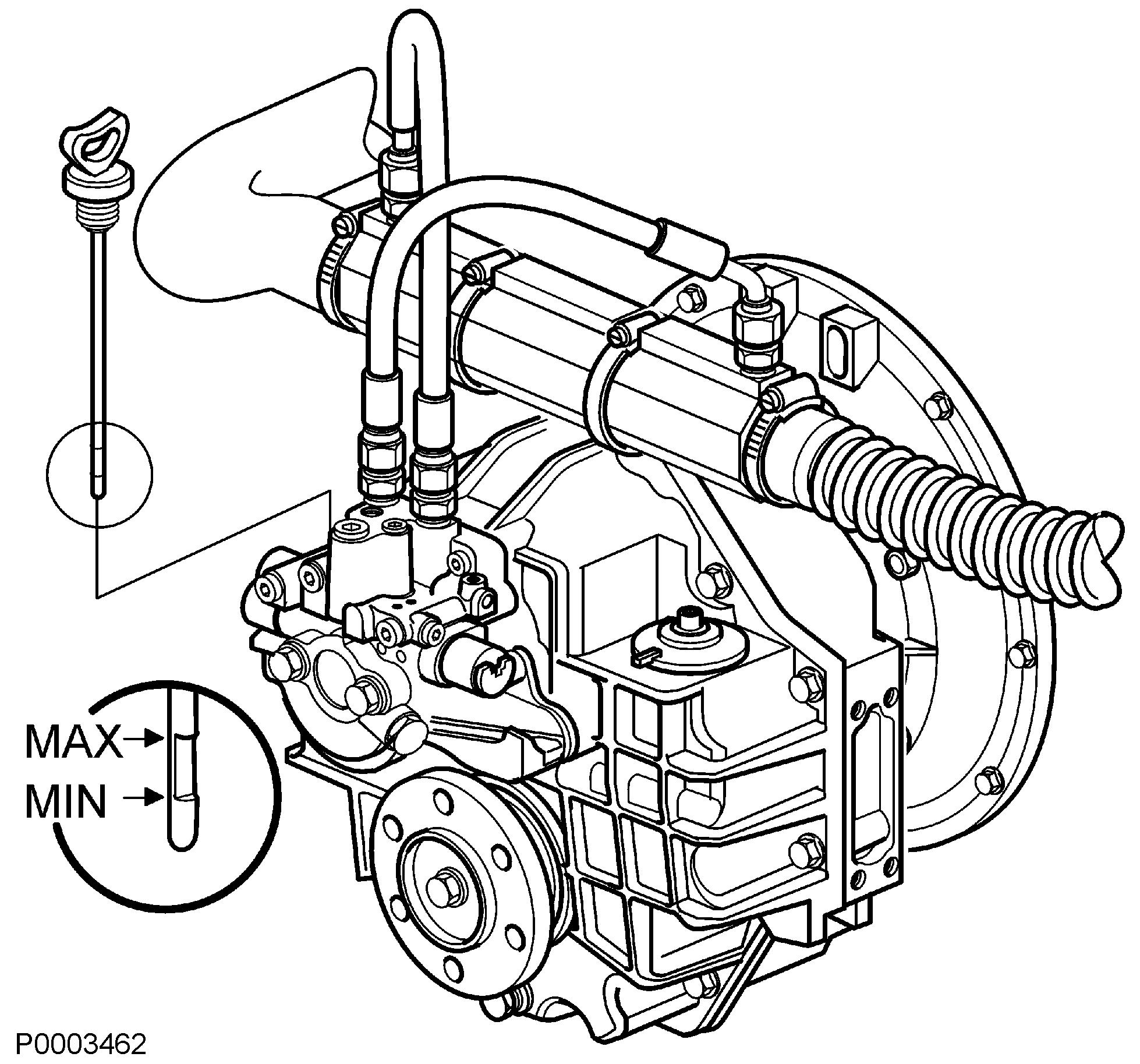
The reverse gear is hydraulic, which means that shifting between ahead/astern and neutral is performed hydraulically. The reverse gear lubrication system is equipped with an oil filter and oil cooler. The reverse gear uses solenoid valves for electronically controlled shifting.
Volvo Penta recommends that a seawater filter be fitted to guarantee the correct cooling water flow to the engine and reverse gear. Otherwise there is a risk of contaminants in the seawater blocking the reverse gear cooler and other cooling system components.
Oil level, checking and topping up
1 Start the engine and let it run on idle a few minutes.
2Remove the dipstick by turning counter-clockwise.
3 Wipe the dipstick and reinsert it in the reverse gear without screwing it in. Remove the dipstick and check the oil level. The correct oil level is between the MAX and MIN markings.
4Top up the oil as required using the dip stick tube. Please refer to section Technical Data page 122 for oil quality and capacity.
IMPORTANT!
Never over-fill the reverse gear. The oil level must always be within the recommended range.
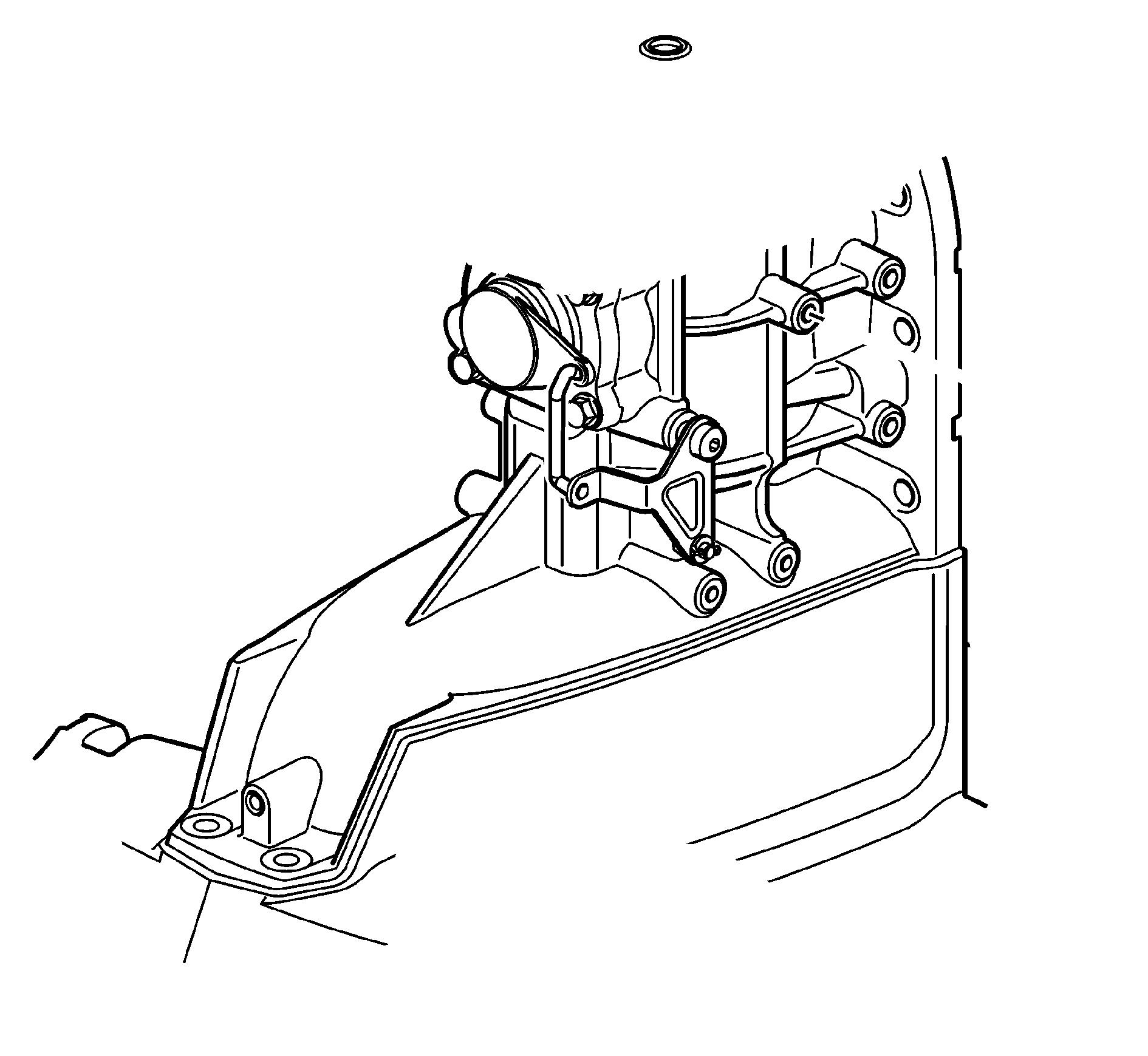
Reverse Gear, Oil och Filter Change
1Clean around the cap (2) so that there is no risk of dirt falling into the filter housing.
2Undo the Allen bolt (1) with a 6mm Allen key. Remove the cover (2). Change the O-rings in the cap; lubricate the new ones.
3Remove the filter (3).
4Use an oil drain pump to pump out the oil from the oil filter housing. Connect the hose to the suction tube (4) in the bottom of the housing. Suction hose maximum external diameter is 16 mm.
5Measure out the correct quantity of oil and fill the reverse gear via the oil filter housing. Refer to the Technical Data page 122 section for oil grade and quantity.
IMPORTANT!
Never over-fill the reverse gear. The oil level must always be within the recommended range.
6Install the new filter (3) in the filter housing.
7Install the cover. Tightening torque: 5-8 Nm
8 Put the control lever in neutral. Start the engine and run it at 1500 rpm for a few minutes so that the reverse gear oil cooler fills with oil.
9Stop the engine and check the oil level. Top up as needed
Propeller Shaft Sealing, Check
If the boat is fitted with a Volvo Penta propeller shaft, the propeller shaft seals must be lubricated before launch and purged directly after launching. Purge the glands by pressing them together, at the same time as they are pressed down onto the shaft. The press approximately 1 cm³ of water resistant grease into the seal.
Drive
The drive is protected against galvanic corrosion by several layers of paint, sacrificial anodes and ground braids. The ground braids maintain a connection between the different components of the drive. A broken connection can result in the rapid corrosion of an individual component even though the protection is otherwise effective. Check ground braids every year. Faulty electrical installation can also cause the break down of the galvanic protection. Damage due to electrolytic corrosion occurs rapidly and is often extensive. For further information see the chapter Maintenance page 88
Always repair damage to paintwork immediately. Improperly applied paint or the wrong type of paint on the keel can put the corrosion protection system out of action. For further information on painting see section Storage page 108
Transmission lubricant, checking and topping up
IMPORTANT!
Never over-fill the drive. The oil level must always be within the recommended range.
1Screw the oil dipstick all the way down and then remove it.
2Check the oil level on the dipstick. The oil must be on the flat dipstick area
If the oil level is low, fill a little at a time through the oil dipstick opening until the right level is reached. For oil grade and quantity refer to Technical Data page 123
If oil level is too high, empty the drive until the correct level is achieved; refer to Transmission Oil, Change page 97.
3Check O-ring on dipstick for wear; replace if needed.
The oil must have a golden brown nuance. If the oil is gray, water has entered the stern drive. In this case let a Volvo Penta workshop carry out checks on the stern drive.
Transmission Oil, Change
Draining
1Trim the sterndrive down to the drive position.
2Remove the propeller; refer to Maintenance page 100
3 Placeacontainerunderthesterndrive.Removethe oil dipstick.
4Remove the plug (1). Allow all the oil to drain from the sterndrive. Hand the oil to a recycling depot.
Filling
1Remove the cover and undo the oil level plug (2).
2Fill new oil through the oil drain hole; use a pump with a 3/8–16 UNC union. For oil grade and quantity, refer to Propulsion Unit
Fill slowly to avoid the formation of air bubbles. When the oil is visible in the oil level hole, the sterndrive is sufficiently full.
3 Check the O-rings on the plug and dipstick; replace as necessary.
Reinstall the oil dipstick and oil level plug.
4Remove the oil pump and screw the plug back in.
5 Check the oil level on the dipstick. Oil must be visible on the flat part of the dipstick. Top up with oil through the oil dipstick hole if necessary.
6Reinstall the cover and propeller.
If the oil has been completely changed, the oil level must be checked again after the sterndrive has been run for a short while to eliminate air pockets.
Checking oil level, power trim
The Power Trim system is a closed center hydraulic system. Regular checks of the fluid level are not necessary, but if functionality deteriorates check the fluid level in the Power Trim system.
1Trim the sterndrive down to maximum. The sterndrive must be fully trimmed down when the fluid level is checked or fluid is filled in order to show the correct level.
Position the sterndrive hard astarboard to access the trim pump.
2Clean the area around the filler cap (1) to prevent dirt from entering the trim system.
3Remove the filler cap. The fluid must reach all the way up to the hole.
Fill with Volvo Penta Power Trim and steering fluid as necessary.
Corrosion protection, checking and changing
Check the anodes regularly. Replace with new anodes when approximately 1/3 of an anode has corroded away.
When the boat is stored ashore, corrosion protection deteriorates due to anode oxidization. Even new anodes may oxidize on the surface; always clean/sand them before launch.
IMPORTANT!
Use emery paper. Do not use a wire brush or other steel tools when cleaning, as these may damage the galvanic protection.
Thesterndriveisfittedwithaluminumanodesasstandard, intended for use in salt water. If the sterndrive is to be used principally in freshwater, the anodes must be magnesium.
Use anodes according to the following:
• Zinc in salt water.
• Magnesium in freshwater.
• Aluminum when the boat is used primarily in salt water and sometimes in brackish water.
Replacement of anodes
1Remove the anode retaining screws.
2Clean the contact surface.
3 Installthenewanodesandtightenthemsothatthey make good contact with the underlying metal.
Drive Unit Bellows
WARNING!
Secure the drive unit in a raised position in such a way that it cannot fall when working on the drive bellows. A falling drive may cause serious injury.
• Check that there are no splits or damage to the bellows. Replace bellows as necessary. Keep the surfaces clean; fouling on the bellows may puncture them.
• Inspect the inside of the bellows for signs of contact with the universal joint when the drive is removed. Internal wear is a sign that the engine has be run at too high rpm with the sterndrive in an inclined position.
• Check that the clamps are correctly installed.
Propeller
For best performance and fuel economy, maximum engine revolutions must correspond to the maximum propeller revolution range; refer to Engines. If maximum engine revolutions exceed the propeller revolution range, the propeller must be replaced. Ask your Volvo Penta dealer for advice if you wish to switch to a propeller with a different pitch and diameter. In twin installations one propeller must have right rotation and the other left rotation. Both must have the same pitch and diameter.
Damaged propellers must be replaced as soon as possible. If a boat must be driven with a damaged propeller, do so with extreme caution and only at reduced rpm.
WARNING!
Make sure the engine can not start during work on propeller(s); remove ignition key(s) and shift drive into forward or reverse.
SX propeller
WARNING!
Make sure the engine can not start during work on propeller(s); remove ignition key(s) and shift drive into forward or reverse.
Removing the propeller
Lock the propeller shaft
1Remove the five bolts and remove the cover (1) from the sterndrive.
2 Remove the cotter pin (2) from the shift cube (3) to which the gear shift cable (4) is fastened. Remove the shift cube and washer (5) from the lever (6) without turning the cube.
3Put the sterndrive into gear by hand by pulling the lever to either the forward position (F) or reverse position (R).
Alternatively, the propeller can be locked by putting the transmission in neutral and placing a block of wood between the cavitation plate and one of the propeller blades.
Removing the propeller
1Remove the cotter pin (1) and the lock washer (2).
2Remove the nut (3).
3Remove the spacer (4), the propeller (5), and the bushing (6).
4Wipe the propeller (7) shaft clean.
Install the propeller
1 Switch on the ignition and move the control lever to neutral. Remove the ignition key from the ignition switch.
2Thoroughly lubricate the propeller hub and propeller shaft with Volvo Penta grease (part # 828250).
3 Install the bushing (6) with the inner cone facing the sterndrive.
4Install the propeller (5) on the propeller shaft (7); align the splines and slide the propeller toward the bushing until the splines are visible.
5 Install the spacer (4) on the propeller shaft splines.
6Install and tighten the propeller nut (3) so that the propeller and the bushing (6) bottom completely.
7 Undothepropellernutandscrewitbackagainstthe spacer by hand. Then tighten the propeller nut a further 1/3 to 1/2 turn.
Alternatively, use a torque wrench and torque the propeller to 96–108 Nm.
8Align the lock washer (2) against the propeller nut so that it lines up with the cotter pin hole.
9Install the cotter pin (1) and bend out the ends to secure the nut. Use a new cotter pin if necessary.
10Turn the shift lever to the neutral position. Attach the wire to the shift arm. Install a new cotter pin.
11Install the cover and bolt it in place.
12Check that the propeller can be turned easily.
DPS propeller
WARNING!
Make sure the engine can not start during work on propeller(s); remove ignition key(s) and shift drive into forward or reverse.
Removing the propeller
Lock the propeller shaft
1Remove the five bolts and remove the cover (1) from the sterndrive.
2 Remove the cotter pin (2) from the shift cube (3) to which the gear shift cable (4) is fastened. Remove the shift cube and washer (5) from the lever (6) without turning the cube.
3Put the sterndrive into gear by hand by pulling the lever to either the forward position (F) or reverse position (R).
Alternatively, the propeller can be locked by putting the transmission in neutral and placing a block of wood between the cavitation plate and one of the propeller blades.
Removing the propeller
1Undo the aft propeller nut (1) and remove the aft propeller (2).
2Remove the forward propeller nut (3) and remove the forward propeller (4).
3Wipe the propeller shaft clean.
Installation
1Thoroughly lubricate the propeller hub and propeller shaft with Volvo Penta grease (part # 828250).
2Fit the forward propeller (4).
3 Install the forward propeller nut (3) and torque to 60 Nm.
4Install the aft propeller (2).
5Install the forward propeller nut (1) and torque to 100 Nm (75 ft.lbs.).
6Turn the shift lever to the neutral position. Attach the wire to the shift arm. Install a new cotter pin.
7Install the cover and bolt it in place.
8Check that the propeller can be turned easily.
Steering Parallel rod
Check the parallel rods connecting the two stern drives together, especially after running aground or striking an underwater object.
If a parallel rod is bent, loose or damaged it must be checked by your Volvo Penta workshop.
WARNING!
If the parallel strut (tie bar) shows signs of damage, run at reduced speed to harbor. The parallel strut is a vital safety component, damage may effect steering characteristics. In the worst case steering could be lost altogether. Never align or weld a damaged parallel strut. Please contact your nearest authorized Volvo Penta workshop for assistance.
Steering System Operation
Power steering reservoir fluid level
The steering servo tank has a transparent reservoir whichmakescheckingthelevelpossiblewithoutopening the cap. The fluid level must be between the “MIN” and “MAX” lines. Whenever you check the engine oil, also check the steering reservoir fluid level.
WARNING!
Use only by Volvo Penta recommended fluid and grade. Any non-appproved fluid may cause loss of steering or result in damage to the components used in the steering system.


