1 minute read
Electricand Electronic Systems


The Florence architecture permits the exchange of information between the various ECU’s through different levels of telecommunication networks. The networks are the following:
C-CAN Network
I-CAN Network (M139 only, used for TV and data communication )
B-CAN Network
K Network (serial-line for diagnostics of the C-CAN nodes)
A-BUS Network
W-BUS Network(serial-line connecting the Body Computer and the Bosch Motronicfor recovery of the immobilizer)
The complete structure of the FLORENCE network is illustrated bythe following figure that represent the MaseratiQuattroporte, and it comprises three different levels of network for CAN communication:
•The C-CAN Network for the dynamical control of the vehicle’s powertrain (high speed network)
•The B-CAN Network for the comfort functions of the vehicle’s bodywork (low speed network)
•The I-CAN Network (MaseratiQuattroporteonly) for the data communication and the TV -the infotainment system
The C-CAN e B-CAN networks are interconnected through a gateway for the transfer of common information located inside the Body Computer Node (NBC).
The abbreviations of the names of the nodes in the two vehicles are presented in the table.
Electricand Electronic Systems
A-BUS:
The A-BUS is a serial line with a MULTIMASTER management system working with a velocity of 4800 baud. It is utilised to exchange information between the control units and to perform the diagnostics, and is a terminal to terminal communication. The transmitting and receiving ECU’s are always identified. Please note that even if the communication is terminal to terminal, the ECU’s connected to the line might be more than two. In the case of a conflict between two ECU’s in simultaneous transmission, there is a well defined priority table which gives each control unit the permission to regain access to the bus.
The control units connected through the A-BUS on the FLORENCE network are:
• CSP (Rainand TwilightSensorECU)
• CAV (MotionAlarmECU)
• CTC (Windscreen Wipers ECU)
• CSA (Alarm System Siren ECU)
THE BODY COMPUTER IS THE HEART OF THE SYSTEM:
Interface function for all of the networks
Gateway between the B-CAN and the C-CAN networks
Master of the Network Management
Master of the A-BUS Network
Slave in the W-BUS Network
Master of the K-line
Diagnostic interface (EOBD connector)
Interface towards the CPL (dashboard control unit for the piloting of functions)
Diagnostics on the CAN-line for the B-CAN Network
IMMOBILIZER unit incorporated
POSITION OF ECUsAND NODES
Electricand Electronic Systems
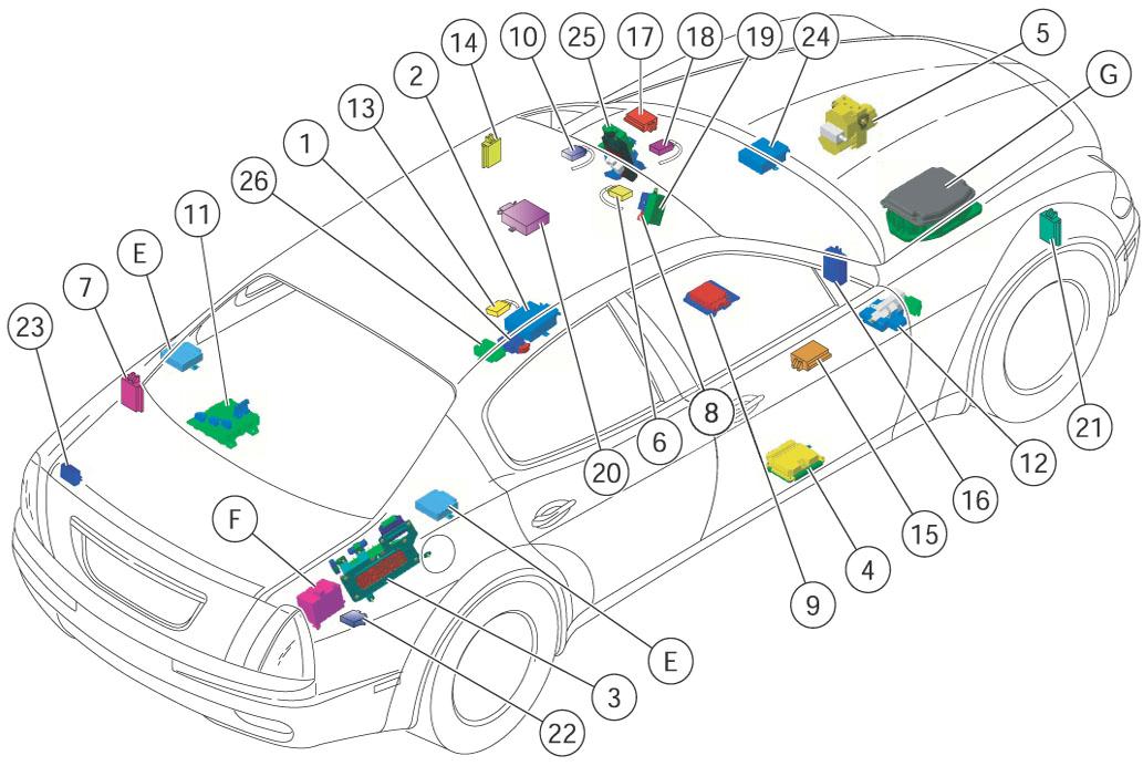
HEADLIGHT SET-UP ECU (CAF)