7 minute read
IntroductiontoMaserati


Initial Run
Modular TransmissionShaft
The INITIAL RUN phase is a data acquisition phase performed by the tester. The tester measures the shaft unbalance and stores the data as a basis for comparison of the subsequent measurements
For data acquisition, the transmission shaft must run at a speedbetween 2850 –3150 RPM (equivalent to 2800 engine RPM read on the instrument panel when 5th gear is selected) and must be kept at this speed throughout the data acquisition phase.
To easily reach the required RPM, set “SEQUENTIAL MANUAL”operation to progressively arrive at engaging 5th gear.
Hold the accelerator pedal depressed until reaching the requiredRPM values, keep them constant throughout the data acquisition phase and wait for the result.
Initial Run OK
If the data acquisition phase is successfully completed, it means that the tester has been calibrated using an unbalance value that does not exceed the maximum value set in the tester.
Subsequently, you automatically go to the TRIAL RUN phase.
Initial Run NOT OK
If the data acquisition phase is not completed successfully, it means that the tester has measured an unbalance value that exceeds the maximum value set in the tester.
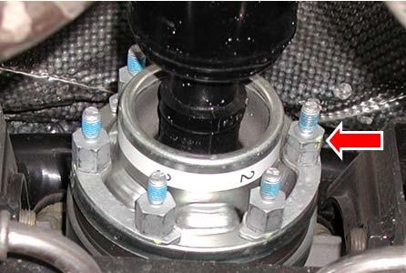
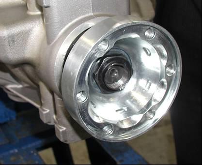
The system will automatically prompt you to position a rebalancing weight of 4.5 grams on the flange stud bolt marked with number 1 (Position 1).
Repeat the INITIAL RUN phase.
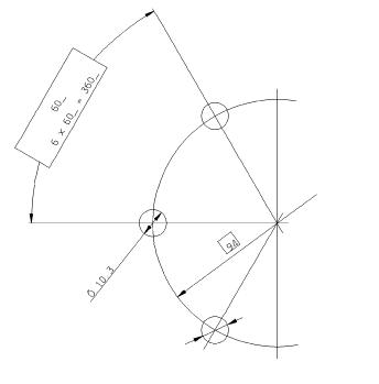
If the unbalance value is still not compensated, the system willautomatically prompt you to move the rebalancing weight from Position 1 to Position 2 and torepeat the INITIAL RUN phase. This process will be repeated (going through the various positions from 1 to 6) until the correct position for the rebalancing weight is found.
Once the correct position for the rebalancing weight has been found, you will automatically go to the TRIAL RUN phase
CAUTION. If the correct position for the rebalancing weight is not found, remove the rebalancing weight of 4.5 grams and repeat the cycle using a weight of 7.5 grams.
Once the correct position for the rebalancing weight has been found, you will automatically go to the TRIAL RUN phase
CAUTION. If the correct position for the rebalancing weight is not foundeven when using the weight of 7.5 grams, carefully check all the components connected to the transmission shaft (rear differential, axle shafts etc.).
When you have inspected all the mechanical components, repeat the entire cycle with the rebalancing weight of 4.5 grams (7.5 grams if necessary).
If the procedures fails again, contact the Maserati Technical Service Department
CAUTION!
Should the adhesive tape bearing the corresponding number for each stud bolt not be present, it is important to assign the correct numbering: affix the number 1 in correspondence to a stud bolt and then the other numbers with clockwise orientation.
Trial Run
This is the phase where the tester reads the various positions to correct the unbalance. The TRIAL RUN phase consists of two different actions, dependingon whether or not the INITIAL RUN is completed successfully the first time it is performed.
a) INITIAL RUN OK on first attempt. The system automatically prompts you to position a reference weight of 4.5 grams in Position 1 b) INITIAL RUN NOT OK on first attempt. The system automatically prompts you to position a reference weight of 4.5 grams in the position where the rebalancing weight is present.
Start the TRIAL RUN procedure from the SD3.
CAUTION. In condition (a) described above, the reference weight of 4.5 grams in Position 1 might cause an excessive unbalance not readable by the tester.In this case, the tester will automatically prompt you to position the same reference weight in Position 4. Repeat the TRIAL RUN phase with the weight in Position 4.
The TRIAL RUN procedure ends with a page displaying a table:
A: Ideal value (information only)
B: Number of the flange stud bolt where you have to position the first correction weight (whose value in grams is indicated in the next column)
C: Number of the flange stud bolt where you have to position the second correction weight (whose value in grams is indicated in the next column)
Remove the reference weight of 4.5 grams previously positioned. Apply the correction weights as described in the table. Click on NEXT to go to the “FINAL RUN”phase.
Final Run
This is the phase where the tester reads and assigns the weightsfor unbalance correction. Continue the procedure and follow the on-screen instructions. Continue applying the correction weights as described in the tables that will be displayed.
Continue until the tester indicates an IDEAL VALUE in the table lower than or equal to 2.1 grams Having reached the correct value, click on “EXIT”and confirm to print the test.
Important
The procedure does not end automatically but only by selecting “EXIT”. The procedure is complete when the transmission shaft is balanced.
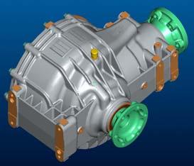
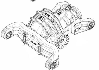
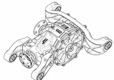
Graziano Differential
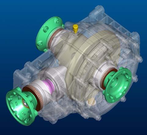
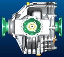
Graziano Differential
The limitedslip differentialbuiltby Graziano isusedin the Quattroporte and GranTurismoin combinationwith the ZF automatictransmission (M139GQ and M145BL)
The rear differential compensates for the different wheel movements. The configuration of this differential provides for:
•25% locking during acceleration
•45% locking during deceleration
It is fastened to the chassis by means of specific cast iron mounts
Technical Specifications
Self-locking differential , Limited Slip type
Oil type: Shell SpiraxS 75W140
Quantity: 1litre
Bevel gear pair: spiral with involutegear tooth profile
Final drive ratio for GranTurismo: 15/56
Final drive ratio for Quattroporte: 13/46
Support bearings: tapered rollers
Pinion axial clearance restored by means of a collapsible spacer
Checking the clearance between the crest and the tooth of the pinion and crown wheel:
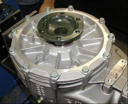
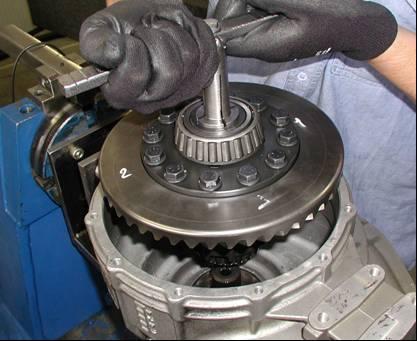
Undo the retaining screws of the differential housing cover. Remove the axle shaft coupling flange and the relative bearing. Then turn over the cover and remove the snap ring from the inside.
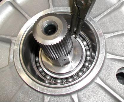
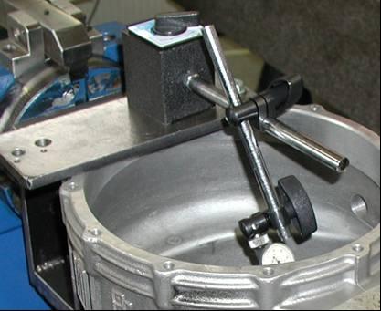
Place the cover in a press and, using a punch of suitable dimensions, remove the differential flange shaft. Fit the differential cover and temporarily secure it with three or four screws, then fit a base (1) onto it, which must be screwed onto one of the cover fittings.
Position a dial gauge with a magnetic mount (2) on the base (1).
IntroductiontoMaserati
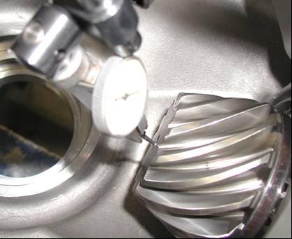
The plunger of the dial gauge must be positioned on the crown wheel diameter marking (Æ224mm), shown on the specific tool.
Check that the clearance between the pinion and the crown wheel is between 0.08 and 0.10 mm
If the value falls within the specified values, complete the assembly stages.
Remove the magnetic mount, the dial gauge and the differential cover.
Place the cover in a press and, using a punch of suitable dimensions, fit the differential flange shaft.
Fit the snap ring.
Refit the cover and tighten the differential housing cover retaining screws to a torque of 28.5 –31.5 Nm
Replacing the flange O-ring on the transmission shaft side and checking the end float of the pinion
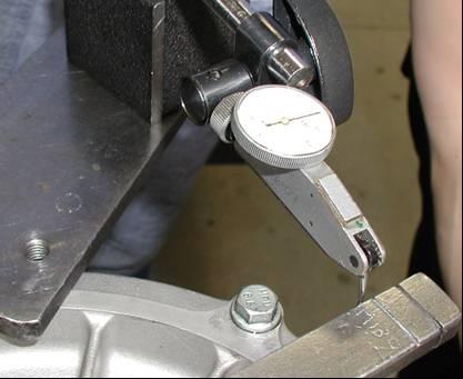
Before removing the fastening ring nut, check the residual rolling torque using a torque wrench with dial indicator on the flange nut. The inspection must be performed when the differential is removed or when the axle shafts are disconnected and without oil. With the differential crown wheel removed and without oil, the rolling torque must be equal to 1Nm ±0,5 Nm. With the complete differential, without oil and with the axle shafts disconnected, the rolling torque must be 3Nm ±1Nm. This torque must be checked once again after the flange has been tightened. Using a suitable punch, remove the two flattenedparts of the flange retaining nut
Graziano Differential
CAUTION!
The flange retaining nut must be replaced each time it is removed
Apply a tool on the flange to lock its rotation, unscrew the nutand remove it.
Remove the oil seal from its seat. Clean the O-ring residues off the flange striking surface. Then fit a new O-ring and a new oil seal using a dedicated tool.
CAUTION!
There must be NO end float of the pinion. The end float is eliminated by tightening the flange nut on the transmission shaft side. There is no specific tightening torque. It is recommended to apply a pre-torque and then check the end float value.
IntroductiontoMaserati
Fit the flange, apply LOCTITE 270 and screw on a new retaining nut. Apply a tool on the flange to lock its rotation. Using a specific bushing, screw on the retaining nut.

IMPORTANT:
The nut tightening torque is related to the end float read by the dial gauge on the pinion and by the residual rolling torque.
Pre-tighten the new ring nut that secures the flange. Tighten increasing the torque value torque by 5÷10 Nm at a time, after having duly checked the end float and rolling torque.
With the differential crown wheel removed and without oil, the rolling torque must be 1Nm±0.5;
With the complete differential, without oil and with the axle shafts disconnected, the rolling torque must be 3Nm ±1Nm.
When the end float is equal to zero and after checking the rolling torque, stop the tightening procedure and flatten the ring nut that secures the flange.
If you have to replace the flange O-ring on the transmission shaft side (if the differential is on the bench) it is advisable to also check the clearance between the crest and the tooth of the pinion and crown wheel. CAUTION!
Undo the retaining screws of the differential housing cover. Remove the axle shaft coupling flange and the relative bearing. Then remove the entirecrown wheel of the selflocking unit.
IntroductiontoMaserati
After fitting the differential assembly, it is advisable to check that the clearance between the pinion and the crown wheel has not changed and that the measurement falls within the indicated values: 0.08 –0.10 mm for the 13/46 final drive (Quattroporte) and 0.08 –0.11 mm for the 15/56 final drive (GranTurismo) a
Remove the magnetic mount, the dial gauge and the differential cover. Place the cover in a press and, using a punch of suitable dimensions, fit the differential flange shaft. Fit the snap ring.
IntroductiontoMaserati
Nominal tightening torques for engine/gearbox assembly-transmission coupling:
IntroductiontoMaserati
Electricand Electronic Systems
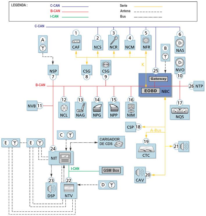
Present Situation Of Multiplexed Architectures In The Group
Electronic architectureforsmallcars:
VENICE (VEhicle Network with Integrated Control Electronics)
•Mod. 188 (Fiat Punto)
Electronic architectureformedium cars:
VENICE PLUS or miniFLORENCE
•Mod. 937 (Alfa 147)
•Mod. 192 (Fiat Stilo)
Electronic architectureforluxurycars:
FLORENCE (Fiat Luxurycar ORiented Network Control Electronics)
•Mod. 841 (Lancia Thesis)
•Maserati M139 & M145