2 minute read
IntroductiontoMaserati


When refitting, follow the removal procedures in reverse order and tighten the Mechatroniccontrol unit screws to a torque of 8.0 ±0.8 Nm following the sequence shown in the figure below.
•Position the vehicle as level as possible on the car hoist.
•It is essential that the gearbox oil temperature is between 50°C and 60°C
•It is advisable to check the level when the oil temperature is 55°C
•Connect the SD3 tester and access “SERIAL DIAGNOSTICS”
•Subsequently Select "INDIVIDUAL ECU DIAGNOSTICS”
•Then select the vehicle and the ECU involved.
•Wait for the ECU and serial number to be loaded.
•Select “PARAMETER ENVIRONMENT” and then “GENERAL PARAMETERS 1”.
•Then access the vehicle data and read the “TRANSMISSION OIL TEMPERATURE” value.
•Starting the checking procedure:
•Check the oil temperature : If the temperature is above 60°C, wait until it cools down.
•If the temperature is below 50°C, move the gearshift lever to REVERSE and then to DRIVE, holding it in each position for at least 3 seconds.
•Always keep the wheels locked.
•Check the temperature with the SD3 tester; if it has risen to about 55°C, turn off the engine and then search for the gearbox ECU errors and delete them.
ZF automatic6-speed gearbox
•Start the engine and let it run in idle, then unscrew the oil filler cap (1).
•The sump is filled “to the brim”with oil, therefore if oil spills out when the cap is unscrewed, no top-up is necessary.
•WITH THE ENGINE OFF: position the tool in the filling hole on the sump and pump in oil until it starts spilling out.
•WITH THE ENGINE IDLING: continue filling with gearbox oil until it starts spilling out
•Keeping the engine running, connect the SD3 tester and access “SERIAL DIAGNOSTICS”
•Subsequently Select "INDIVIDUAL ECU DIAGNOSTICS”
•Then select the vehicle and the ECU involved.
•Wait for the ECU and serial number to be loaded.
•Select “PARAMETER ENVIRONMENT” and then “GENERAL PARAMETERS 1”.
•Then access the vehicle data and read the “TRANSMISSION OIL TEMPERATURE” value.
•Check that the gearbox oil temperature is between 50°C and 55°C.
•Continue filling with oil until it starts spilling out.
•Tighten the oil filler cap (1) to a torque of 60 Nm
CAUTION! EXCLUSIVELY USE OIL TYPE SHELL M1375.4 ATF
Modular TransmissionShaft
Modular TransmissionShaft
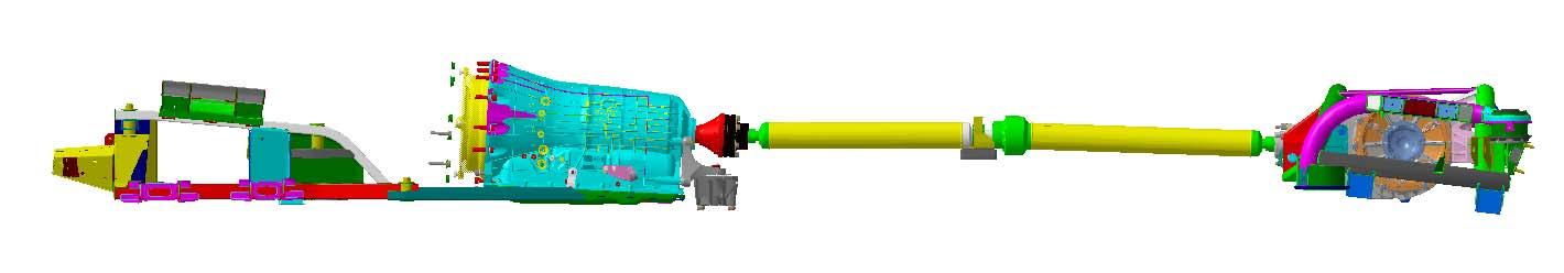
For vehicles fitted with the ZF automatic transmission, a new modular transmission shaft is applied. The shaft needs to be balanced after removing one ormore components of the transmission system. This is done using tool DSE1, by applying balancing weights on the differential coupling flange.
The modular transmission shaft was chosen for technical reasons, due to the different alignment of the engine axis with respect to the rear differential axis, which makes the homokineticalmotion transmission impossible.

Modular Transmission shaft balancing procedure
The balancing kit contains a set of nuts of known weight with which the balancing weight calculated by the instrument must be approximated. As these nutswill be fitted on the retaining bolts of the transmission shaft coupling flanges, the bolts need to be clearly identified so that the fitting positions indicated by the instrument are respected. Actually, unlike wheel balancing, where the balancing weight can be fittedin any position along the perimeter of the wheel rim, in this case there are six fixed positions on the rear of the shaft fastening flange.
The instrument thus divides the result into weights equivalent to the theoretical balancing weight. These weights must be approximated with the available nuts, obtaining an overall effect equivalent to that of one balancing weight.
IntroductiontoMaserati
Modular TransmissionShaft
To perform the test, you need to use the following instruments together with the SD3 diagnostic tester: DSE1 or DSE2
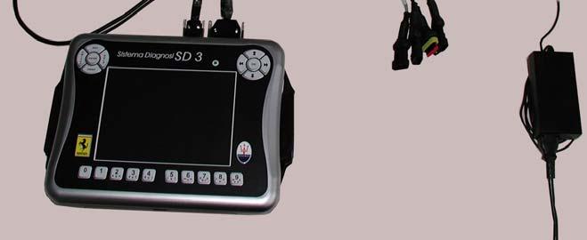

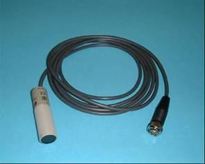
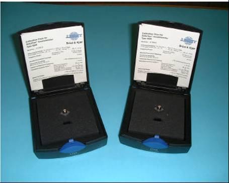
The kit contains two B&K 4508 accelerometers, but only one of the two shall be used for the balancing procedure. The cables required to connect to the DSE1/DSE2 instrument are also provided in the kit.
Prepare the SD3 tester connecting it to the DSE1/DSE2 instrumentand the DC/DC converter, as described below.
1.SD3 connection
2.SD3 connection
3.CAN connector
4.V BATT connector
5.SD3 CBL 07
6.Power supply

7.DC/DCconverter(To beusedonlyin case the EOBD connection isnotused)
8.DSE1/DSE2 instrument
9.Greyconnectorcable RS232 –DSE1/2
10.Black connectorcable SD3 –DC/DC converter