2 minute read
IntroductiontoMaserati


Preparing the vehicle
Position the vehicle on a hoist.
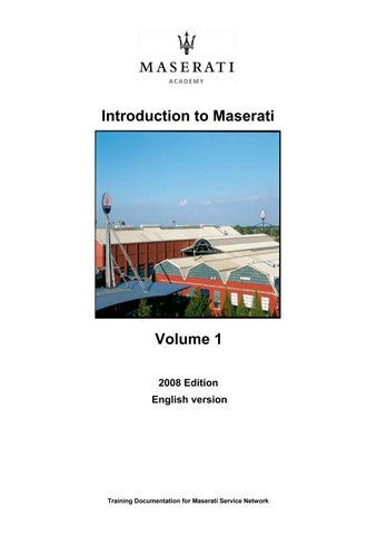
Remove the two rear wheels and position the vehicle on mounts which must be approx. 18 –20 cm high.
These mounts must hold the vehicle level and compensate for the absence of the wheels. Provisionally use the rubber bushings positioned underneath the hub carrier. Specific mounts of predefined height are being tested, and these will rest in a less delicate area to also facilitate levelling the vehicle. Cut some stickers 0.5 cm wide and 4 cm long out of a reflective adhesive sheet of paper.
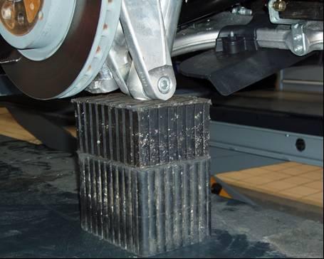
Apply the sticker (A) on the transmission shaft. The sticker must be positioned in correspondence to the flange stud bolt marked with number 1 (B).

If present, remove all the balancing weights applied on the flange stud bolts before starting the balancing procedure.
Positioning the RPM sensor
Position the RPM sensor (3) so that it is fully perpendicular to the ground and in line with the transmission shaft (X), at a distance of approximately 50 cm from the shaft.
To do this, you can, for example:
Fit a mount (1) equipped with a base (2) to support the speed sensor (3). The material is not provided in the kit and must therefore be purchased locally.
Securely fasten the sensor on the relative mount and position it as described above.
CAUTION! Once positioned, the sensor must not be moved for the entire duration of the balancing procedure so as not to alter the reference point for the instrument.
IntroductiontoMaserati
Positioning the accelerometer
Modular TransmissionShaft
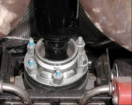
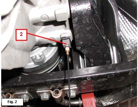
The B&K 4508 accelerometer must be fitted underneath the differential near the transmission shaft (Fig. 2)
Using HEPTANE, remove any residues of glue or grease from the flat surface on the differential where the accelerometer holder will be positioned.
Apply epoxy glue in the centre of the flat surface of the accelerometer holder (1).
Position the accelerometer holder (1) on the differential and hold it down for about 20 seconds, so that it adheres properly.
Fit the accelerometer (2) on its holder (1).

Connecting the DSE1/DSE2 components:
Connect the speed sensor (1) cable and the accelerometer (2) cable to the DSE1/DSE2.

IntroductiontoMaserati
Balancing cycle with SD3. (Phase I)
Start the SD3 tester, access the “SERIAL DIAGNOSTICS”environment and then “INDIVIDUAL ECU DIAGNOSTICS”.
Select “TOOLS”and then “ALL”.
Select the item relating to transmission shaft balancing for the vehicle M139EV07. A page will be displayed showing the following options.
DISPLAY DATA
ACTIVATE BALANCING
SET TEST WEIGHTS
UPDATE CARD
EXIT
Select “UPDATE CARD”.
A page will appear showing the software version installed on SD3and on DSE1/DSE2. If the software version of DSE1/DSE2 does not coincide with the version installed on SD3, update it by selecting “YES”. If this is not the case, select “NO”and return to the home page.
Select “ACTIVATE BALANCING”.
With the help of a second operator seated in the vehicle, start the engine, check that the EPB (Electronic Parking Brake) is disengaged and manually deactivate the MSP function. Select “SEQUENTIAL MANUAL”gearbox operation.
Balancing cycle with SD3. (Phase II)
The shaft balancing procedure is divided into three phases:
INITIAL RUN
TRIAL RUN
FINAL RUN
All three phases are guided “step-by-step”by the SD3 program. We recommended that you carefully follow the instructions displayed on the SD3.