6 minute read
IntroductiontoMaserati


Introduction
ZF automatic6-speed gearbox
A completely new automatic six speed gearbox (ZF 6HP26) was introduced for the Maserati Quattroportewith automatic transmission, presented in January 2007. Also the Maserati GranTurismouses the same gearbox for the automatic transmission version. The Gearbox is built by ZF and has been developed in cooperationwith Maserati and Bosch (electronic control) to offer the best possible compromisebetween driving dynamics, fuel economy and comfort. The gearbox contains 6 electro-hydraulically controlled gears and a torque converter with lock-up clutch and anti-slip function. The automatic gearbox has a self-adaptive control system that adjusts the type of gearshift strategy, selecting the gear most suited to the driving conditions and driving style. The driver can choose from four different driving modes: Auto Normal, Auto Sport (selectable by pressing the SPORT button), Low-grip /Auto ICE (selectable by pressing the ICE button) and Manual (selectable by shifting the gearshiftlever from "D" to the left). For the Auto Normal and Auto Sport driving modes there are two different types of gearshifting, automatically selected by the gearbox/engine control system based on the driving style (detected through the accelerator pedal and the intensity of lateral and longitudinal acceleration) and the gradient of the road.
Electronic control:
The electronic control of the gearbox is the “MECHATRONIC”type, meaning that both the hydraulic and the electronic control unit are integrated in a single unit inside the gearbox. This ECU provides dynamic gear ratio selection and has a sequential gear selection program. The adaptive shift strategy memory can be reset by performing the Cycle function with SD3 diagnostic tester. By doing this the gearshiftstrategy will return to its default settings.
Technicalspecifications
Maximum torque:max 600 Nm
Torque converter: Hydrodynamic converter with regulated clutch
Cooling system: Oil/water exchanger positioned underneath the engine intake manifold

Gearbox oil: Shell M1375.4 ATF (no oil change or refilling required)
Oil quantity:
• Gearbox without converter and oil radiator: 5.8 l
• Torque converter: 3.7 L
• Oil radiator with relative pipes: 0,525 L
Total weight: 142 kg (including oil and gearbox oil radiator)
Gear ratios:
Parts available for servicing:
•Torque converter (complete unit)
•Mechatronic(complete unit)
•Oil sump
•Oil sump sealing
•Oil filter
•Rubber oil sleeves (4 pieces)
•Rubber oil supply sealing Mechatronic
•Input shaft oil sealing
•Output shaft oil sealing
•Output shaft flange and locking nut
•Oil sealing behind output shaft flange locking nut
Gearboxmechanical
ZF automatic6-speed gearbox
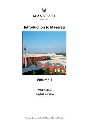
The mechanical transmission devices are made up of planetary gears. The components are driven by an electro-hydraulic system which incorporates the hydraulic and electronic control units in a singe control unit (Mechatronic) fitted on the gearbox.

Engine power reaches the transmission by means of a hydrodynamictorque converter with integrated lock-up type clutch (WK).
The 6 forward gears and the reverse gear are obtained by means of a double planetary gear (Ravigneaux) and a front-mounted simple planetary gear. The integrated operating modes of the planetary gears are patented (Lepelletier). The individual gear ratios are obtained by deviating the incoming torque flow through the various planetary gear components and by braking others. For this purpose various couplings and brakes are used.
Gear disengagement control logic
A further innovation is the option of automatic disengagement when the vehicle is stationary. This means that the gearbox is disconnected from thekinematic mechanisms when it is in standby (clutch A open). This results in a furtherreduction of fuel consumption.
With the engine idling, the vehicle stationary and the gearshiftlever in “D”, the torque converter transmits a specific torque value that slightly moves the vehicle forward if the brake pedal is not applied. If the brake pedal is applied, the converter is forced to dissipate the power by slowing down the engine RPM, which must be compensated by increasing the minimum torque (by further opening the throttle) until obtaining the correct idling RPM. This results in higher fuel consumption and greater force required on the pedal (for example, to hold the vehicle stationary when stopping at trafficlights or stop signs) which clearly negatively affects driving comfort and handling. Disengagement therefore occurs if a gear is engaged when the vehicle is stationary, depending on different parameters monitored by the gearbox node.
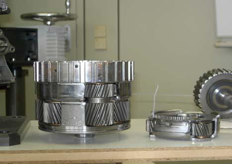
The torque converter is composed of a toroidal-shaped chamber containing two elements: a centrifugal pump connected to the crankshaft and a hydraulic or turbine motor positioned in front of the pump and connected to the gearbox input shaft. The two parts face but do not touch each other and the chamber is filled with low-viscosity oil. The pump is basically a wheel with radiallyarranged blades. When turning, it pushes the fluid towards the outside by effect of the centrifugal force. The fluid also acquires angular momentum. The motor is likewise composed of a bladed wheel. The liquid that the pump pushes to the outside of the device is forced to return to the centre through the turbine blades, driving it so that it rotates.
Coated collar (converter with lock-up clutch)
Piston (converter with lock-up clutch)
Converter cover
ZF automatic6-speed gearbox
Pump
Turbine Stator
One way clutch
Convertor hub
Stator hub

Turbine hub
Converter stub axle
Flywheel fastening
Once the fluid has returned to the centre, it is again ejected by the turbine thus completing the cycle. Even if the motor section is off, the spiral movementof the fluid produces a twisting moment at the output. The torque converter has, by nature, a slipping feature which causes a loss of energy in the form of heat dispersed by the fluid. To improve energy efficiency, modern converters are equipped with an integrated clutch system which mechanically joins the pump and the motor when the onboardcomputer detects a constant cruising speed. The torque converter (“Trilok" converter) is composed of a pump wheel or impeller, a turbine and a flow reaction component (stator) which multiplies the torque delivered.Another important element for converter operation is the oil used for torque delivery.
Lock-upclutch
ZF automatic6-speed gearbox

Clutch closed Clutch open
A torque converter lock-up clutch (WK) is a device that makes it possible to eliminate the slipping typical of the torque converter and contributes to optimise fuel consumption. The torque converter with lock-up clutch has a controlled activation and release system. During the adjustment stage, there is a minimal difference between the RPM of the pump and that of the turbine. This has allowed us to reduce the vibrations transmitted by the engine before they reach the transmission: this process can be further boosted by the torsion vibration damper. This principle provides smoother gearshiftingand noise reduction.
The lock-up clutch can be activated in any gear, but only in conditions of constant driving speed. The lock-up clutch will be disengaged during acceleration or braking.

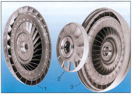
Parking Lockmechanism
ZF automatic6-speed gearbox
Gear
Pin
Leg spring
Drive collar
Parking lock pawl
Locking cone
Compression spring
Connecting rod
Release spring
Engagement collar
Selection lever
Selection shaft
The parking lock mechanism is a device that stops the vehicle from moving. It is activated by a spring when the vehicle is stationary. A pawl wedges into the parking lock gear teeth, thus preventing the transmission output shaft from rotating. Rear axle torque lock is obtained by means of the output shaft.
Warning: only put the selector lever in the Park position when the vehicle is stationary.
ZF automatic6-speed gearbox
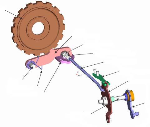
The coupling elements are used for gearshiftingunder load without cutting the power flow.
As engagement components, in addition to the torque converter with lock-up clutch (WK), there are three rotary multidisc clutches (A, B and E) and two fixed multidisc brakes (C and D).
Gearengagement Solenoid valve logic Pressure - electronic pressure control valve Clutch control on converter Central gear 1, double planetary gear Satellite holder, double planetary gear Main pressure Selection valve 1 Brake D Clutch E Brake C
6HP26 Clutch Clutch logic Brake Solenoid valve Clutch control on gear logic Planetary holder, single planetary gear
The Mechatronicmodule is composed of a hydraulic selection control unit and an electronic control unit. The hydraulic, electrical and electronic components are incorporated in a single unit. The Mechatronicmodule is positioned near the gearbox oil sump. The main advantages of this module are: fewer electrical connections (which are subject to faults) and automatic calibration of the hardware by the software. This involves: very accurate tolerances, improved gearshift response, enhanced driving comfort, gearshift quality optimisation, improved reliability thanks to the fewer electrical connections and interfaces.
Electrostatic discharge
For any operations on the Mechatronicmodule, take the appropriate precautions in terms of safety, especially to prevent electrostatic discharge (ESD). The human body, if electrically charged but not properly earthed, becomes an electrostatic “cloud”and may cause damage to the electronic components. It is therefore extremely important to take appropriate precautions, like conductive shoesand ESD protective gloves. To prevent any damage from electrostatic discharge, appropriate precautions must always be taken in the following cases:

•When receiving goods
•In the inspection area of the goods received
•In the workshops, and in the spare parts warehouse even if staying there for only short periods of time
•In the shipping/delivery area
•In the maritime transport or shipping area
•During handling, fitting and removal of the Mechatronicmodule
Keep the packaging material and the ESD protective film so that they can be used when returning the parts removed from the transmission.
ZF automatic6-speed gearbox
Mechatronicunitremoval
In ordertoremovethe mechatronicmodule, carryout the followingsteps:
•Drainthe automaticgearboxoil
•Disconnectthe wiringharnass connectorfromthe adapter(1)
•Undo the 21 Torxscrews that secure the oil sump on the gearbox and then remove the oil sump and the sealing strip.
•Pull down the adapter locking lever (2).
•Remove the connector adapter (3) which is pressure-fitted with two O-rings by pulling it out.
•Undo the 10 torxscrews which attach the Mechatronicunit to the gearbox housing to remove the Mechatronic.
Toremovethe mechatronic, undoonlythe screwsmarkedin red
CAUTION!
Mechatronicunitrefitment
ZF automatic6-speed gearbox


CAUTION!
When the Mechatronicmodule is been refitted, be extremely careful that you correctly fit the gear position selector whit respect to the position sensor.

CAUTION!
Before fitting the Mechatronic module, check that the oil delivery duct is properly positioned.