13 minute read
IntroductiontoMaserati


CD / Jukebox mode
To ensure optimal sound reproduction you are advised to use original CDs.
WARNING: Do not use AUDIO CD or MP3 CD mediums in 8 cm format, not even with a specific adapter; using this format will damage the system. After inserting a CD with the printed side facing up, it will automatically start playing. If you are listening to another audio source and there is already a CD in the player, press the button SOURCE (2) or SCR (27): the CD will automatically start playing.
Fast forward/backward
Press and hold down the button (11) or (16) to fast forward or backward to a track on the AUDIO CD; release them to go back to the normal playing speed.
WARNING: This function is not available for MP3 CD and Jukebox.
CD / Jukebox mode menu
Repeatedly press the MODE button (22) until the AUDIO mode is displayed. Pressing the knob (13) the display will show the following menu:
-Copy CD to Jukebox
-Activate Introscan
-Activate random mode
-Activate repeat
Confirming this function with the knob (13) you will access a submenu containing the following options:
•Copy complete CD
•Multiple selection (allows copying a series of tracks selected by the user)
•Complete album (only with MP3 CD)
•Current track.
During copying in Audio mode only the Radio function is active.
Activate Introscan
Once selected and confirmed, this function allows you to listen to the beginning of all the tracks on the CD or in the Jukebox in actual order. To deactivate this function, press the knob (13) then select "Deactivate Introscan" and confirm.
IntroductiontoMaserati
Configuration mode menu
Maserati GranTurismo
To access the“Configuration”menu, press the MENU button (15), select the icon. the display will show the following menu:
•Display configuration: to select colour, brightness and used units
•Sound: voice command, speech synthesis and buzzer settings
•Define vehicle parameters: settings for speed limit, central door locking, twilight sensor, instrument cluster display and parking sensors.
•Set date and time: note: the analogue central dash panel watch is to set manually.
•Select language
IntroductiontoMaserati
Heating, Ventillationand Air Conditionning(HVAC)
Maserati GranTurismo
The air conditioning/heating system of the GranTurismoprovides enhanced air flow obtained with new and suitably dimensioned air lines. The system has been designed to assure comfort in all possible weather conditions.
Coolant
The coolant used is R134a. PAG RL -897
This vehicle system is filled with: 600 ±20 g of fluid
Lubricant
The fluid used is Oil UconRL897
This vehicle system is filled with: 200 ml ±10 ml of fluid.
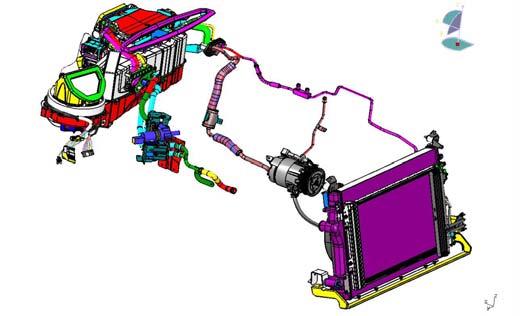
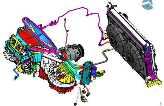
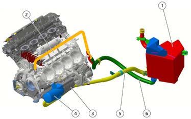
Compressor
The compressor (1) allows the system to vary the flow rate of the coolant reaching the evaporator gradually. It draws the motion directly from the crankshaft by means of the poly-V belt (2).

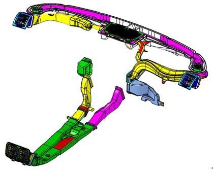

• Front distribution unit: this is the housing inside which the external air, or recirculatingair, is conditioned and distributed to the vents selected by the user. The distribution unit houses air flaps
• Evaporator: this is a heat exchanger housed in the air distribution unit. It is designed to draw heat and humidity from the air blown into the passenger compartment, by exploiting the coolant transformation from the liquid to the gaseous state.
• Radiator heater: this is a heat exchanger connected to the cooling circuit of the engine by means of two lines: one draws the hot water from the engine, the other allows the coolant to return to the engine. The heater is designed to provide the heat required to heat up the air blown into the passenger compartment.
• Air flap actuators
• Air temperature sensors
• Pollen filter: this is a combined air filter for the passenger compartment : particles and active carbons. It is designed to filter the air coming intothe passenger compartment. The first layer (particles) prevents pollens and pollutant particles from entering the passenger compartment; the second layer (active carbons) reduces bad odours due to humidity that forms on the surface)
• The electric fan is controlled by a 12 V brushless electric motor and is operated at different speeds by a signal from the NCL (A.C. system node). Itis located inside the air conditioning/heating unit near the evaporator)
• Anti-mist sensor: the anti-mist sensor is an electronic device which is designed to send a control signal to the recirculation flap: When the windscreen mist index exceeds the preset thresholds, the flap is forced open to allow intake of outside air regardless of the recirculation mode set by the user. When the windscreen mist index returns to the preset acceptable values, the recirculationflap resumes the mode active before this operation. It is fitted on the internal rear-view mirror.
• Sunlight sensor: the sunlight sensor measures the thermal energy generated by the sun. It is positioned on the dashboard near the windscreen. It is a DUAL ZONE sensor, which ensures optimal control over the air conditioning and heating system temperatures.
• Outside air temperature sensor: this sensor (1) is designed to read the outside air temperature. It is an NTC sensor fitted inside the external rearview mirror, on the driver's side. It has an operating range of -40°C / 80°C.
HVAC node (NCL)
The HVAC node (NCL) (1), located on the right-hand side at the front passenger's feet, is fitted on the air conditioning/heating unit. It is connected to the low-speed B-CAN network. The air HVAC node (NCL) receives the following information from the Body Computer node (NBC), through the CAN network:
•outside air temperature
•engine water temperature
•engine RPM
•vehicle speed (tachometric signal)
•battery voltage (battery charge level)
•heated rear window activation
•compressor status
•status of the vehicle lights.
9. Bodywork
The chassis of the Maserati GranTurismoderives from the Quattroporte, but has a smaller wheelbase and rear overhang (wheelbase: -125mm; rear overhang: -66 mm). It is composed of high-resistance boxed steel sheets and incorporates a tubular structure in position with the rear section, which supports the suspension and the differential, and a front section which supports the suspension and the engine. Due to the reduced wheelbase, the torsionalrigidity of the GranTurismochassis has been significantly improved with respect to the Quattroporte.
Different materials and technologies have been used in the construction of the new loadbearing body for optimal weight distribution. The structural component is made of steel, the lid and the front reinforcement cross member of the bumper is made of aluminium, and thermo-hardening plastic was used for the luggage compartment (a technology known as Sheet MoldingCompound -SMC)
The luggage compartment is made out of one single piece that incorporates the aerodynamic lip. As well as offering greater resistance to lightimpacts and corrosion, the SMC technology has allowed reducing the weight of the components and has given the designer the possibility to best express his creative spirit. The high rigidity values allow the suspension to operate with extreme precision, to the advantage of dynamic handling, at the same time reducing vibrations and undesired movements of the internal components. All this amounts to greater driving comfort on any road surface.
Maserati Academy–May 2008
Maserati reservesthe right tomakeanymodificationtothe vehiclesdescribedin thismanual, at any time, foreithertechnicalor commercial reasons. Allrightsreserved. Thisdocumentmustnotbe reproduced, evenpartially, withoutthe writtenconsentof Maserati S.p.A.
Volume 2
2008 Edition
English version

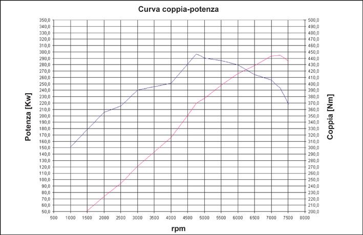
Withthe introductionof the F136 enginefamily in 2001, a newtechnicalarea started forMaserati. Aftera periodofmore than 10 yearsin whichonlyturbochargedengines wereproduced, Maserati returnedtonormalaspiratedengines. Thiswasalsothe first Maserati enginewhichwasnotproducedin-house. Assemblyof thisenginewascarriedout bygrouppartner Ferrari in Maranello, at about20 km from the Maserati factory. Thisnewenginewasthe resultofa closetechnicalcollaboration betweenMaserati engineersand theircolleaguesfromMaranello and istechnicallyan absolutemasterpiece.
Compact and light design; fouroverheadcamshaftsand 48 valveswitha smallvalve angle; dry sumplubricationsystem tolowerthe center ofgravityand allowsufficient lubricationin eventhe mostextremconditions; nicasil-coated aluminiumcylinder liners…allaspectswhichare usuallyreservedforracingengines. Thisengineisfoundin the complete M138 modelrange(F136R) and in a slightly modifiedversion(F136S) alsoin the M139 modelwithDuoselecttransmission.
ENGINE CHARACTERISTICS:

•All-alloy90°V8 over-boreenginewithcompetitionpedigree, compact and light construction.
•Steplessvariablevalve timing withtiming variatorson bothintakecamshafts. This system isoperatedbymeansof a high pressurehydraulicsystem (12-14 bar). A dedicatedhigh pressurepumpisdrivenby the camshaftand a hydraulicpressure accumulatorislocatedunderneaththe intakemanifold.
•Hardenedaluminium/silicon alloy cylinder heads with high volumetric and thermodynamic efficiency combustion chamber.
•Hardenedaluminium/siliconalloycrankcasewith pressed-in nikasilcylinder liners.
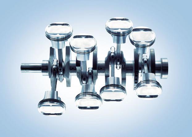
•Single-cast crankshaft in hardened steel, individually balanced, resting on five main journals.
•Fouroverheadcamshafts(two per bank) and four valves per cylinder, driven by hydraulic tappets.
•Chain-driventiming system, withhydraulictensioners.
•Lubrication system with dry sump, oil/water exchanger incorporated into the upper crankcase (inside the V-angle).
•Aluminiumintake manifold for F136R version.
•Plastic intakemanifold, withoptimisedline lengthsforF136S version.
•IntegratedBosch MotronicME7 ignition-injectionwithmotor drive throttle.
IntroductiontoMaserati
SPECIFICATIONS F136R:
Ignition staticignition
Ignition sequence:
Ignition coil: Bosch ZS-K-1X1E
Sparkplugs NGK PMR8A
Alternator Denso 12 V -150 A Battery FIAM 12V 100Ah -850A
IntroductiontoMaserati
SPECIFICATIONS F136S:
12 v -150 A
12V 100Ah -850A
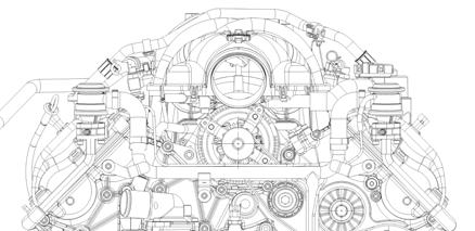
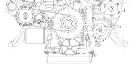
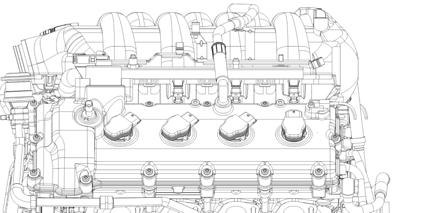
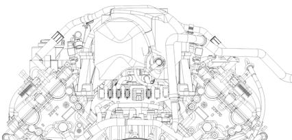
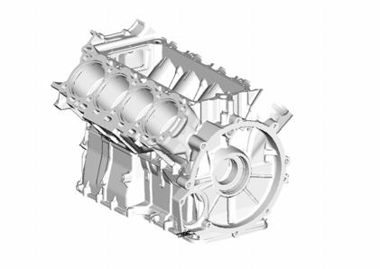
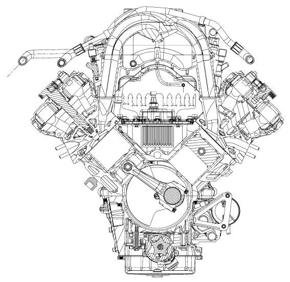
ENGINE VIEWS (F136)
Lubrication System
4200 Dry SumpEngine
The lubricationsystem ismadeup anexternal oil tank (dry sump) and external, multiple oil pump. The oil pumpisdrivenbythe crackshaft mymeansof a chainthe water pumpis incorporatedin the oil pumpand formsa single unit. Thisconstructionallowsa low engine position in the vehiclechassis and guarantees adequatelubrication, even in case of veryhigh lateralaccelerationforces.
1. Engineoil tank
2. Oil/water heatexchanger
3. Water/oil pump
4. Oil filter
5. Line from oil tank to water/oil pump
6. Line from heat exchanger to oil tank
Pumpunit: this geared unit is composed of three purge pumps and one intake pump.
Coolingsystem: the water/oil heatexchanger (2) is incorporated into the engine assembly.
Oil tank: the engineoil tank (1) is made of aluminiumsheet and is located on the righthand side of the engine compartment. It isequippedwith dipstick and filler neck.
Oil levelcheckprocedure:
•Makesurethe vehicleison a flatsurface.
•Start up the engineand waituntilitreachesthe correctoperatingtemperature (water temperature: 90°C)
•Checkthe oil levelwithengineidling byusingthe dipstickon the fillingtap.
•The oil levelshouldreachthe MAX. referenceon the dipstick. Top up ifnecessary.
1. Water/oil pump
2. Thermostaticvalve
3. Radiator
4. Electricfans
5. Expansiontank
Circulation of the coolant is activated by a centrifugalpump, which is chain-driven, together with the oil pumps, by the crankshaft.

Pump
Centrifugalwater pump(1)with by-pass built in with the thermostatic valve (2).
Circuit Max. circuitpressure: 6 Bar
Radiator
The water radiator(3)is positioned on the front of the engine compartment. The electricintakefans(4)are located on the hood and are shared by the water radiator, the AC condenser and the power steering oil cooler.
Expansiontank
Located on the right-hand side (5)
1.Heads
2.Outlet line
3.Oil tank
4.Plenum chamber


5.Line
The device for oil gas and vapourrecirculation is of the closed circuit type. The oil vapoursand the gases coming from the heads (1) pass through the breatherline (2)and a portion of them condenses and flows back into the oil tank (3)while the other portion is taken in by the plenum chamber (4) via the line (5).
Secondary Air System
This system supplies additional air to the exhaust manifolds to allow the catalytic converter to reach their operating temperature quickly.
By means of the solenoid valve (1), the MotronicECU, drives the opening/closing of the two pneumatic valves (2) which actuate the injection of secondary air into the exhaust manifolds (7). The vacuumtank (3) which creates the vacuum required to open the pneumatic valves is located in the engine compartment, underneath the secondary air pump.The secondary air pump (8), managed by the engine ECU, sends air to the exhaust lines.
The pump and the secondary air solenoid valve are activated, after engine ignition, when the coolant temperature is in the range -5 °C to-99°C
The function is active for around 80 seconds, deactivatesforaround 60 seconds and then reactivates for a further 10 seconds. In the latter period the secondary air valve seal is monitored.
The Lambda sensors are disabled for the entire duration of the cycle.

4200 Dry SumpEngine
ENGINE TIMING:
The enginetiming data forforM138 and M139 vehicles are notthe same. Refertothe respectivetiming values foreachengineversion. CAUTION!
The engine timing procedure is identical for both versions, but the values will, of course, be different. The procedure below refers to F136R engines. The different tactics to adopt for F136S engines are described at the end of this timing procedure.

•Turn the engine anticlockwise and position the first piston at the TDC. Make sure that the dial gauge is on zero.
•Place a support for the magnetic base of the dial gauge holder on the right-hand engine head.
IntroductiontoMaserati
4200 Dry SumpEngine
•Position a magnetic base with a long-rod centesimal dial gauge.
•Turn the engine clockwise positioning the intake cam immediatelybefore the opening ramp.
•In this condition, the hydraulic tappet is still in the rest position.
•Position the dial gauge plunger above the tappet of an intake valve. The dial gauge rod must be as perpendicular as possible to the tappet surface.
•Reset the dial gauge that measures the movement of the intake tappet.
•Again, position at the TDC and check the dial gauge previously reset. In this position (TDC), the intake valves of the first cylinder have already started their travel. Therefore, carefully check the position on the dial gauge positioned on the tappet.

•Turn the crankshaft 15° beyond the TDC. This corresponds to a piston stroke of 1.75 mm beyond the TDC.
•Check that the tappet downstroke(begun before the TDC) and hence the intake valve upstroke is 0.59±0.08 mm.
•Should the values measured in these conditions be out of tolerance, hold the crankshaft still, loosen the Allen screws on the timing variatorand turn the intake camshaft until obtaining the desired intake valve upstroke. For this reason, as described earlier, it is advisable to get ready for the timing procedure by positioning the variatoradjustment slots in the centre of the angular adjustment.
•Checkthe timing again.
•Use a torque wrench to tighten the previously loosened Allen screws that secure the variatorto a torque of 15 Nm, after applyingLoctite242.
4200 Dry SumpEngine
EXHAUST TIMING ADJUSTMENT PROCEDURE (F136R)
•Turn the engine clockwise and position the first piston at the TDC with the camshafts balanced (exhaust closed and intake open). Make sure that the dialgaugeison zero.
•Position the dial gauge plunger above the tappet of an exhaust valve. The dial gauge rod must be as perpendicular as possible to the tappet surface.

•Reset the dial gauge that measures the movement of the exhaust tappet.
•Turn the crankshaft clockwise until an exhaust valve is closed.

•Check that the closing stroke of the exhaust valve is 1.09±0.08 mm.
•Should the values measured in these conditions be out of tolerance, hold the crankshaft still, move the centering dowel anticlockwise or clockwise (depending on whether you want to delay or anticipate the shaft) until obtaining the desired timing value.
•Insert the fixing dowel into the hole immediately after or before the centering dowel, whichever is easier.
CAUTION!
The tightening action of the exhaust gearwheel considerably affects the exhaust timing adjustment. Take this into account when adjusting the exhaust timing to the indicated value.
IntroductiontoMaserati
4200 Dry SumpEngine
•Use a torque wrench to tighten the M20x32 mm hex-head screw of the exhaust camshaft(with relevant washer) to a torque of 200 Nm after applyingLoctite242.
•Checkthe timing again.
CAUTION!
Tighten the M20x32 screw to the indicated torque taking care to lock the exhaust camshaft so that the timing chain is not loaded.
•Carry out the same procedure for the left-hand cylinder bank, positioning the dial gauge holder on cylindernumber8.

IntroductiontoMaserati
INTAKE TIMING ADJUSTMENT PROCEDURE (F136S)
4200 Dry SumpEngine
•Turn the engine anticlockwise and position the first piston at the TDC. Make sure that the dialgaugeison zero.
•Place a support for the magnetic base of the dial gauge holder on the right-hand engine head.
•Position a magnetic base with a long-rod centesimal dial gauge.
•Turn the engine clockwise and position the intake cam immediately before the opening ramp. In this condition, the hydraulic tappet is still in restposition.
•Position the dial gauge plunger above the tappet of an intake valve.
•The dial gauge rod must be as perpendicular as possible to the tappet surface.
•Again, position at the TDC and check the dial gauge previously reset. In this position (TDC), the intake valves of the first cylinder have already started their travel. Therefore, carefully check the position on the dial gauge positioned on the tappet.
•Turn the crankshaft 15° beyond the TDC. This corresponds to a piston stroke of 1.75 mm beyondthe TDC.
•Check that the downstrokeof the tappet (begun before the TDC) and hence the valve upstroke is 0.59±0.08 mm.
•Should the values measured in these conditions be out of tolerance, hold the crankshaft still, loosen the Allen screws of the timing variatorand turn the intake camshaft until obtaining the desired intake valve upstroke. For this reason, as described earlier, it is advisable to get ready for the timing procedure by positioning the variatoradjustment slots in the centre of the angularadjustment.
•Checkthe timing again.
•Use a torque wrench to tighten the previously loosened Allen screws that secure the variatorto
•a torqueof 15 Nm after applyingLoctite242.
EXHAUST TIMING ADJUSTMENT PROCEDURE (F136S)
•Turn the engine clockwise and position the first piston at the TDC with the camshafts balanced (exhaust closed and intake open). Make sure that the dial gaugeison zero.
•Position the dial gauge plunger above the tappet of an exhaust valve. The dial gauge rod must be as perpendicular as possible to the tappet surface.
•Reset the dial gauge that measures the movement of the exhaust tappet.

•Turn the crankshaft clockwise until an exhaust valve is closed.
•Check that the tappet downstrokeand hence the exhaust valve upstroke is 0.57±0.08 mm.
•Should the values measured in these conditions be out of tolerance, hold the crankshaft still, move the centringdowel anticlockwise or clockwise (depending on whether you want to delay or anticipate the shaft) until obtaining the desired timing value.
4200 Dry SumpEngine
•Insert the fixing dowel into the hole immediately after or before the centeringdowel.
CAUTION!
The tightening action of the exhaust gearwheel considerably affects the exhaust timing adjustment. Take this into account when adjusting the exhaust timing to the indicated value.
•Use a torque wrench to tighten the M20x32 mm hex-head screw of the exhaust camshaft (with relevant washer) to a torque of 200 Nm after applyingLoctite242.
•Checkthe timing again.
CAUTION!
Tighten the M20x32 screw to the indicated torquetakingcare to lock the exhaust camshaft so that the timing chain is not loaded.
•Carry out the same procedure for the left-hand cylinder bank, positioning the dial gauge holder on cylindernumber8.
This new 4.2L wet sump engine (F136UC –F136UD) is derived from the F136S engine but has been deeply re-engineered and characterized by technical contents that substantially differentiate it from the previous version.

The most important technical innovation is the adoption of a wetsump lubrication system. High torque and power values have been maintained and are assured by the well known technical contents of the “Dry sump”engine. They have been optimised and reengineered for reliability.
This is a unit that forms part of the new generation of Maseratiengines, designed for the debut at the beginning of 2007 on Quattroportemodels with automatic gearbox. Little later this new engine also found its way under the bonnet of the all-new GranTurismomodel.
Both engine versions (F136UC for QuattroporteAutomatic, F136UD for GranTursimo) are technically identical. The only difference lies in the engine control software with a specific engine mapping. This results in a more alert response to accelerator commands and a slightly higher power output for the GranTurismo.
IntroductiontoMaserati
ENGINE CHARACTERISTICS:
•Compact and lightweight construction (180kg)
•Short-stroke engine (bore: 92mm, stroke: 79,8mm)
•Cylinder heads in hardened aluminium/silicon alloy with high volumetric and thermodynamic efficiency combustion chamber.
•Crankcase in aluminium alloy and hardened silicon, completely redesigned with cast iron cylinder liners.
•Single-cast crankshaft in hardened steel, individually balanced, resting on five main journals
•Wet-sump lubrication system with oil pump integrated in the engine and oil-water exchanger integrated in the upper part of the crankcase.
•Cooling circuits operating by circulation of an antifreeze mixture, and water circulation pump driven by the engine pulley.
•Plastic intake manifold, with optimised line lengths.
•Steplessvariable valve timing system for the intake camshafts. It is activated by means of a low-pressure hydraulic system.
•Four overhead camshafts (two per bank) and four valves per cylinder, driven by hydraulic tappets.
•Timing controlled by chains whose tension is guaranteed by two hydraulic tensioners.
•Bosch MotronicME7.1.1 integrated ignition/injection system with motor driven throttle