16 minute read
ABS operatingprinciple


1.Vehiclespeed
2.Wheel speedduringbraking
3.Wheel acceleration
4.Solenoidvalve current
5.Pressurein the braking wheel’s hydrauliccircuit
Stage 1) Wheel deceleration nearing limit:lockingrisk(-a )
Stage 2) Circuit pressurereduction: brakeforce reduction, wheeldecelerationreduction

Stage 3) Pressuremaintenance: wheel speed decreases, then rises again
Stage 4) Pressureincrease: wheel acceleration to value + A
Stage 6) Peripheral acceleration reduction
Stage 7) Maintenance
Stage 8) Pressureincrease: wheelacceleration+a, vehicleand wheel speeds similar Stage 9) Maximumpressure: maximumbrakeforce
Operation speed: From 4 to 10 adjustments are carried out every second,depending on the friction conditions.Processing takes just a few milliseconds.
CAUTION!
Performance of the ABS system isstronglyaffectedbythe conditionof the wheel/tyreassembly. Forthe correctoperationof the system itisof mostimportancethatthe vehicleisfittedwithrims, tyresand brakepads approvedbythe manufacturerand in perfectworking order.
There are two solenoid valves for each circuit branch:
Inletsolenoidvalve (9):

0 Volt = Open = Pressure on caliper
12Volt = Closed= Maintenance
Outlet solenoidvalve (10):
0 Volt = Closed = No Pressure Relief
12Volt = Open = PressureRelief
On Low PressureAccumulator2
Scavengepump(4)delivers oil back to brake master cylinderhigh pressureaccumulator(5)
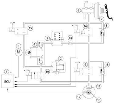
1 ECU
2 Low pressureaccumulator(tank)
3 Scavengepumpcontrol motor
4 Scavengepump
5 High pressureaccumulator (dampingchamber)
6 Brakecontrol master cylinder
7 Brakeservo
8 Fast pressurereductionvalve
9 Inletsolenoidvalve
10 Outlet solenoidvalve
11 Brakecalliper
12 Rpmsensor
13 Toothedwheel
14 Restraint
ASR operatingprinciple
The purposeof ASR istomaintaintraction(and thusguaranteethe longitudinalstabilityof the vehicle) whenthe driven wheelshavethe intentionof skidding. Thisisusefullwhile curving(dynamicloadtransfer betweenboth drivenwheels), whenexcessiveengine torqueistransmittedtothe wheelsor in situationsof low adherance. Whenskidding occurs, ASR managesthe followingoperations:
• 1°step: applyingthe brake(s) of the skiddingwheel(s)
• 2°step: reduction of torque delivered from engine:
•Reductionof sparkadvancing
•Reductionof throttlevalve opening and injectionduration
Note: The thresholdof interventionof the ASR system isset at a higherlevelwhenthe vehicleisdrivenin Sport mode.

EBD operatingprinciple
EBD reducesthe hydraulicpressureon the rearbrakecircuit whenexcessivedeceleration of the rearwheelsisdetected.
MSP (stabilitycontrol) operatingprinciple
This system monitors the vehicle’s stability during cornering. ESP can apply the four brakes independently to bring the vehicle back on track if a dangerous situation for the vehicle’s stability is detected (control of the lateral stability of thevehicle). Besides applying the brakes, MSP can also temporary deactivate automaticgearshiftingin order not to compromise the vehicle’s stability in emergency situations.
The MSP ECU processes the following signals:
•steering angle, steering wheel rotation (steering angle sensor is located on the steering column)
•lateralaccelerationand yaw(a combinedlateralacceleration/ yawrate sensoris locatedon the centraltunnel, nearthe vehicle’s centreof gravity.
•throttlevalve position
•Rotation speedof eachwheel
•hydraulicbrakesystem pressure(pressuresensorintegratedin HU)


Note: Forbothsteeringangle sensor/ lateralaccelerationand yawrate sensor, a calibrationprocedure isrequiredafter replacement.
The MSP system withitsintegratedfunctions(ABS, EBD, ASR, MSR, ESP) is designedasa safetynet onlytosecure the vehicle’s stabilityin emergency conditions. Thankstothe Quattroporte’s well-balancedchassis, ideal weight distributionand limitedslip differential, MSP doesnothavetointerventunder normaldrivingconditions. Thisisone of the aspectsthatmakefromthe Quattroporte a superiordrivingmachineamongstthe luxurysaloons.
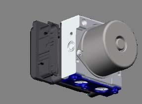
Bosch ABS/ESP 8.0
Fromassemblynumber24275 onwards, a new generation of the integratedABS/stability control system wasadoptedtoreplacethe currentBosch ABS 5.7 system. The Bosch ABS 8.0 system integratesthe followingfunctions: ABS, EBD, ASR, MSR, ESP and Hill Holder. The variousoperationstrategiesof the system haveremainedunchanged. The onlydifferencefromthe costumer’s pointof viewisimprovedcomfort duringABS/EBD interventionthankstoa more refinedsystem operation.
ModificationswithrespecttoBosch ABS 5.7 system:
•Basic functionshaveremainedidentical
•Reducedweightby25%: from3 kg to2,2 kg
•Reduceddimensionsby30%: from2,5 l to1,6 l
•Possibilitytoupload software updates.
•Improvednoisebehaviouron account of new inletvalvesand pumpmotor speed control.
•Control of system pressurein ASR or ESP operationbyPWM control of the electrovalveand failsafemonitoring.
•Submersible HU due to tight accumulator design and sealed motor.
•Improved performance of integrated ECU.
•Introduction of the Hill Holder function.
ElectricParking Brake(EPB)
Withthe introductionof the Quattroporte Automatic, a new, electrically-operatedparking brakewasintroduced.

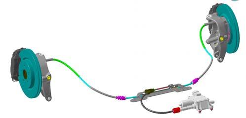
EPB system overview:
The system consistsof the followingcomponents:
•Electro-mechanicEPB actuatorwithintegratedECU
•Drumparking brakes, integratedin the rearbrakediscs
•Brakecablesand divider
•EPB activationlever
•EPB Off switch
•Emergencyreleasetool
•Parking brakewarninglight
IntroductiontoMaserati
EPB operatingstrategies:
Assisted parking brake
The parking brake can be engaged and disengaged when the vehicleis stationary by pressing the EPB activation button on the centre console. To ensure activation of the EPB system, pull and hold the lever positioned on the gearshift lever console for about 2 seconds. The system can be deactivated by holding the brake pedal depressed and pulling the lever
2
Automatic parking brake
Automatic parking brake engagement when the vehicle is stationary and the key is turned OFF (default condition); this function can be disabled by the EPB OFF switch on the central console before turning the key to OFF.
The PARK OFF switch positioned on the central console must be pressed before switching off the engine to prevent automatic activation of the EPB. The message PARK OFF is displayed on the instrument panel. The system is disabledonly for next key-off action, and when the engine is next started the default status is reset.
When the electric parking brake is engaged, the specific warning light comes on. The EPB activation status is displayed on the instrument panel in the display area (EPB ON or EPB OFF).
Whenthe EPB isengaged, the parking brakewarninglight ison.
Parking brakewarning light (EU, Japan specifications)
Parking brake warninglight (US specifications)
Key-ON conditions
The parking brake is always active by default (PARK ON) and is not displayed on the instrument panel.
When pressing the PARK OFF switch, the PARK OFF message is displayed on the multifunctional display for 5 seconds.
Subsequently, if the PARK OFF switch is pressed again, the PARK OFF message disappears and is replaced with the message PARK ON, which is displayed for 5 seconds and then disappears.
Key-OFF conditions
When turning the key from ON to OFF, the EPB activation status is displayed on the instrument panel, regardless of whether PARK ON or PARK OFF has been set. If the engine is turned off when the PARK OFF function is active, the EPB function can be reactivated by commanding the EPB activation switch. The new strategy suggested will be shown on the display as EPB ON.
Drive away
Automatic parking brake disengagement during acceleration (accelerator pedal angle >3%), always active.
Pre Release (from MY08 onwards)
Dynamic brake
Dynamic braking (while the vehicle is moving) is controlled by the ABS/VDC system until the vehicle is stopped, Keeping the EPB button active. In these conditions braking is controlled through the four brake calipers. When the vehicle has come to a stop, the parking brake is automatically engaged.
EPB control logic

It must be possible to activate (but not deactivate) the parkingbrake also when the engine is off and for this reason, a specific power management strategyhas been introduced. The EPB is connected to the C-CAN line for communication with other control modules and for diagnosis.
With the EPB, the ABS/VDC unit (NFR) is the system master and the EPB unit the slave. Therefore, it is the ABS/VDC unit that determines when and how to activate/deactivate the parking brake depending on the driving speed and the surroundingconditions (e.g., slope, engine on/off, engine power delivered, etc.).
EPB emergency release procedure
If the EPB has jammed (complete system failure, dead battery,…) a special tool is required to manually release the parking brake cables. This toolcan be found in the tool kit, delivered with the vehicle. A small opening can befound in the wall behind the driver’s seat. To release the EPB, insert the tool in the tube and turn clockwise until the parking brake cables are fully released.
Note: after having performed the emergency release, the EPB system has to be calibrated with SD3. Therefore the vehicle has to enter an authorised service point.
IntroductiontoMaserati
EPB SD3 functions:
Control cable release
If replacing one or more components of the EPB system (control cables, brake shoes, etc.) the cable tension must be slackened until fully releasing the cables: this will allow you to remove the different parts.
Actuator calibration
Calibration is an operation whereby the nominal operating position of the ECU is set. In brief, the ECU pulls the cables until the nominal tension is attained, determining the zero position in the actuator stroke. This operation is absolutely essential after having removed or replaced components of the EPB system or after performing theemergency release procedure.
EPB function for cable running-in function (Cable Bedding)
If one or both the system cables are replaced, a running-in procedure must be performed using the SD3 tester. This procedure, which repeatedly tensions the cables in 5 different steps, allows the system to reach maximum operating efficiency, preventing residual elastic effects during the operating phases.
EPB running-in function (Garage Braking)
This function enables a running-in procedure of the parking brake shoes, to be performed after the rear brakes have been replaced.
Quattroporte
EPB system failure
The electric parking brake failure information is sent to the instrument cluster via a signal from the B-CAN line. In these conditions, the “EPB failure”warning light comes on (for all markets except the USA where the BRAKE warning light is used) and at the same time a “Parking brake failure”message is shown on the display. This specific message is accompanied by an acoustic warning.
In case of a ABS/VDC system failure, also the EPB functioningwillbedisabled, this becausethe EPB unitiscontrolledbythe ABS/VDC unit.
CAUTION!
EPB failurelight
EPB failurelight (US specifications)
when performing the emergency release procedure, a specific DTC will be stored in the EPB unit, indicating the mechanical release of the EPB. If afterwards the vehicle is driven and thus the EPB intents to operate, another DTC will be stored indicating the non-calibrated status of the EPB actuator.
In this case the EPB has to be mechanically released again, followed by the calibration procedure with SD3. Afterwards DTCshave to be deleted.
Note: in particular conditions where the battery voltage is low, the electric parking brake system may temporarily be deactivated. Therefore, typically uponstarting the engine, when the battery voltage is reduced, the message PARK OFF may betemporarily displayed, indicating that automatic operation is momentarily disabled.
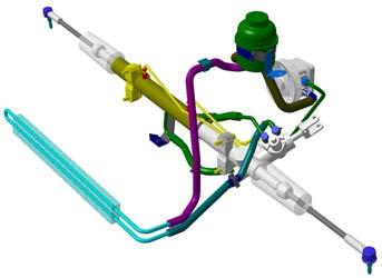
5. DrivingControls
1. Hydraulicsteeringpump
2. Steeringrack
3. Coolingradiator
4. Hydraulicfluidreservoir
5. Steeringangle sensor
The Quattroporte isfittedwithrackand pinionsteeringsystem madebyTRW. The hydraulicpower steeringisvehiclespeedsensitive. An electro-valvelocatedon the steeringrackvariatesthe degreeof poweringbycontrollingthe hydraulicflow. This electro-valveiscontrolledbythe CSG unit(Centralina Servo Guida) and basedon the vehicledrivingspeed. Bythisway the steeringfeeland the neeededsteeringforce are alwaysin accordancewiththe drivingconditions.


Specifications:
•Colapsible, electricallyadjustablesteeringcolumnwitheasy entry function
•Steeringangle sensorlocatedon steeringcolumn(forMSP)
•Speedsensitive power steering
•Beltdrive hydraulicpower steeringpump
•Hydraulicsteeringfluidradiator
•Minimum steeringdiameter: 12,3 m
•Steeringrackratio: 60 mm / revolution
•Steeringrackstroke: 200 mm
•Hydraulicfluid:
Note: for MY07 and QuattroporteAutomatic, a new steering rack was introduced with new control valve with a larger number of internal grooves for greater driving accuracy and enhanced filtering of road bumps.
6. Suspensionsand Wheels
Front suspension


Quattroporte
•Articulated quadrilateral independent wheel suspension with double oscillating triangle
•Anti-dive and anti-squat geometry
•Forged aluminium levers, aluminium hubcarrier
•25 mm øarticulated stabilizer bar on ball joints
•Aluminiumhydraulicshock absorbers withSkyhookvariabledamping control
•Suspension mounted on a separate frame rigidly connected to the bodywork
Rearsuspension
•Articulated quadrilateral rear independent wheel suspension with double oscillating triangle
•Anti-dive and anti-squat geometry
•Forgedaluminiumlevers, aluminium hubcarrier
•24 mm øarticulatedstabilizerbaron ball joints
•Aluminiumhydraulicshock absorbers withSkyhookvariabledamping control
•Suspension mounted on a separate frame rigidly connected to the bodywork
IntroductiontoMaserati
Quattroporte
Withthe introductionof MY07 and Quattroporte Automatic, a numberof modifications wereadoptedtoimprovethe drivingcomfort and stability:
•The upper levers of the front suspension have been modified in the connection area to the chassis in order to house a larger bushing, using a softer and radially asymmetrical rubber, so as to allow the wheel centre to move further backward in the event of longitudinal impact (basically, the upper lever turns during opening on longitudinal impact).
•The fixing points of the rear toe-in control links has been slightly modified in order to reduce toe-in variations caused by vertical wheel movements
Quattroporte Automatic:
On top of the modificationsdescribedabove, the shock absorbercalibrationsforthe Quattroporte Automatichavebeenmodifiedtoenhancedrivingcomfort and adopttothe differentweightdistributionof the vehicle.
IntroductiontoMaserati
Tyrepressure monitoring system (Optional)
The Quattroportecan be optionally fitted with a Tyre Pressure Monitoring Systemor TPMS (standard for Sport GT and Sport GT S). The system consistsof a TPMS control module (NTP) located in the drivers side floor area which receives information related to the tyre pressure and tyre temperature from 4 antennas located in the wheel arch areas. The 4 antennas receive data sent by the sensors which are integrated in the wheel valves. Each sensor has its own ID code, which is sent together with pressure and temperature related data using radio waves. The NTP sends information related to the TPMS to the instrument cluster (NQS) over the B-CAN line.
TRIP button: push this button to display the tyrepressure information for 10 seconds.
Information displayed:
-System temporarily inactive (for example : external radio interference)
-System not calibrated (for example : a tyrehas been replaced )
-System failure
-System not active (if it is disabled by the diagnostics system)
-Low pressure or puncture in front LH, front RH tyresor rear LH and RH tyres
-Low pressure or puncture in unidentified tyre
System Calibration
After replacing or inflating one or more tyres, the system must be calibrated. This condition will be indicated on the information display by a message and the TPMS indicator light. To calibrate the system, press and hold the calibration button, located near the front ceiling light, for a time ranging between 4 and 10 seconds. The system takes a maximum of 20 minutes to complete the calibration procedure withthe vehicle in motion, during which the message "Calibration started”will appear on the information display. If the user recalls the information page showing the pressure levels of each tyre, dashes “–.–”will be viewed in the place of the status.
Skyhooksuspension
The Maserati Quattroporte isequippedwithSkyhookcontinuousvaribledampingcontrol. Thissystem adaptsthe dampingrate of the shock absorbersin functionof the drivingstyle and the road conditions.
An ECU controlssolenoidvalvesinside the shock absorbersbasedon the signalsfrom varioussensorsand informationsreceivedfromothervehiclesystems(receivedbyCAN line). Skyhookmonitorsin continuationthe verticalaccelerationof boththe vehiclebody and the wheelsbymeansof specificsensors.
By calculating the relative body/wheels speed, it modifies the damping force of each wheel in terms of compression and extension to curb the absolute motion of the vehicle body in a vertical direction, as if the body were hooked up to the sky with a shock absorber.
With respect to a conventional system, Skyhook offers superior damping comfort while body roll and pitch angles during dynamic driving are reduced.
Notes:
•The Skyhookdampingsettingisaffectedbythe selecteddrivingmode (Normal/ Sport). In Sport mode, the emphasislieson the drivingprecisionand the reductionof body rolland pitchangles, whilein Normalmode precedenceisgiventocomfort.
•The Skyhookcontrol software forthe Quattroporte Sport GT isspecific, in orderto offera more firmride and higerdrivingaccuracy.
•The Skyhookcontrol software forthe Quattroporte Automaticisspecifictomeetthe changedweightdistributionof the vehicle, in ordertomaintaina balancedsetup.
•Skyhooksuspensionisnotavailableon the Maserati Quattroporte Sport GT S
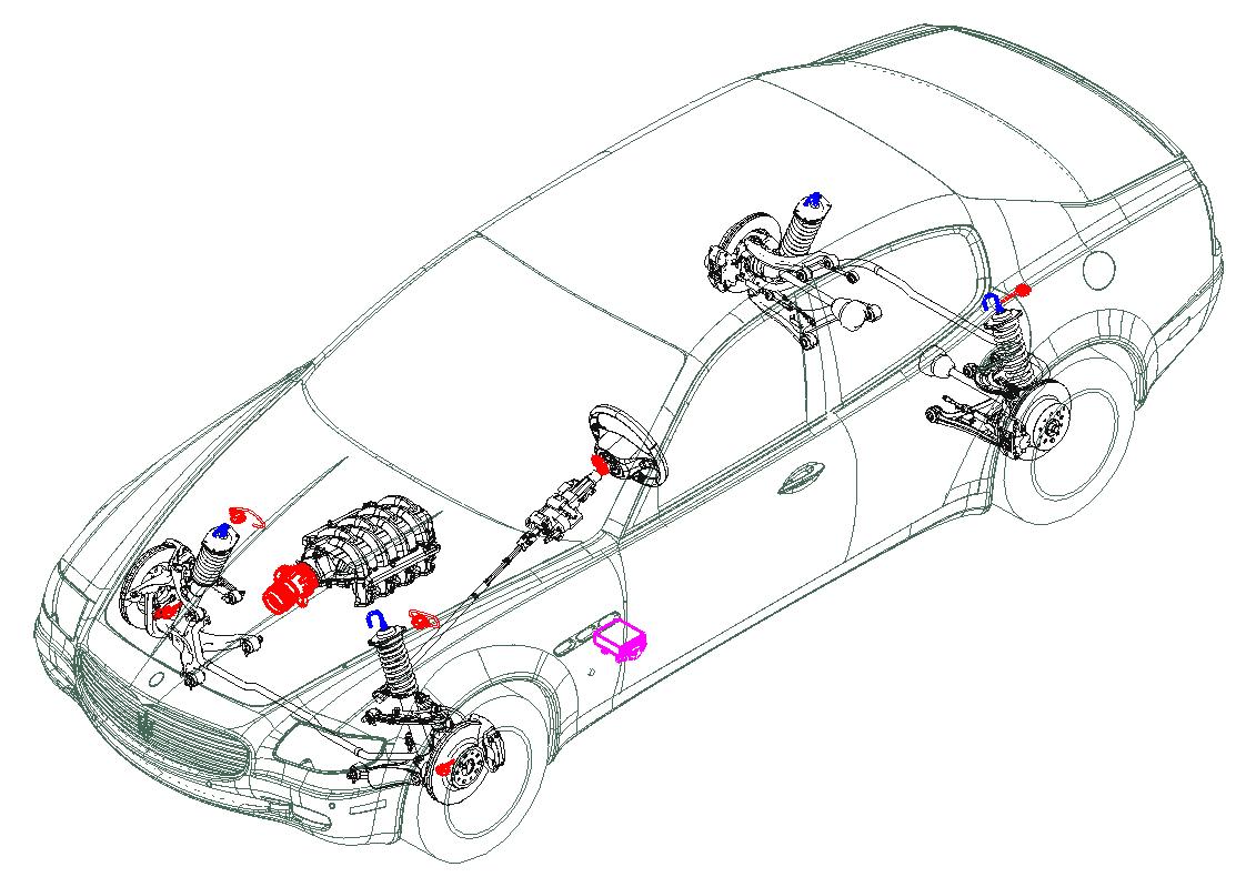
Skyhooksystem layout
1 Front shock absorbers
2 Rearshock absorbers
3 Electronic control unit(Sachs)
4 Front wheelaccelerationsensors
5 Body verticalaccelerationsensors

The Skyhooksystem isthe resultof a cooperationbetweenMaserati and Sachs and consistsof the followingcomponents:
•4 telescopicshock absorberswithintegratedCDC (ContinuousDampingControl) valve
•Electronic control unit(NCS –Nodo Controllo Sospensioni), locatedin the lefthand side floorarea and connectedtothe C-CAN line
•Twofront wheelverticalaccelerationsensors, mountedon the front hubcarriers
•Twofront body verticalaccelerationsensors, mountedon the body closetothe front suspensionstruts.
•One rearbody verticalaccelerationsensor, mountedon the rearcross member.
Each shock absorber has an integrated solenoid valve which is commanded by the Skyhook ECU (NCS). The value of the current passing through the solenoid valves changes the opening of a calibrated orificethrough which the damping fluid flows, thereby defining the damping factor and thus the shock absorber setting.
Vehiclegeometry
Whenadjustingthe vehicle’s wheelalignment, followthe sequenceasindicatedbelow:
Ride height(front and rear)
Camberrear
Toein rear
Casterfront
Camberfront
Toein front
•The vehicle’s geometry must be verified during “static load” configuration, that is, with all the fluids on level tanks, the fuel tank full (90 litres) and 75 kg on each front seats.
Caution Caution
•When verifying the vehicles geometry, it’s of most importance that the tyresare at the correct pressure and all components related to the wheel suspension are in good condition, without broken or deformed parts.
•See the workshop manual for more details and reference images.
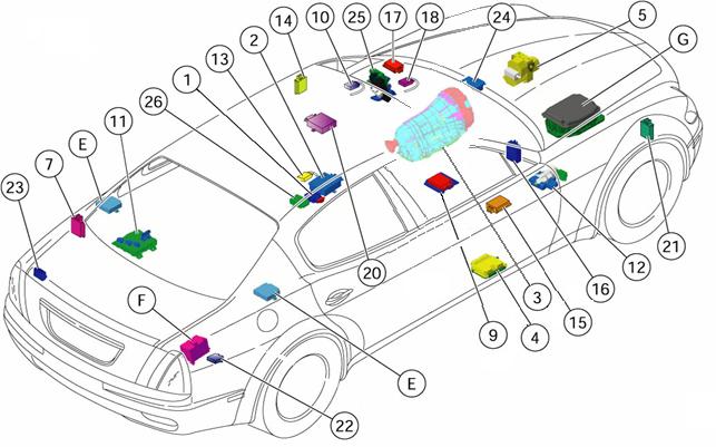
7. SafetyComponents
The Maserati Quattroporte isequippedwithtwodual-stagefront airbags, twoside airbags integratedin the front seats, twowindow bagsand pretensionersforall4 seatbelts. The system isoperatedbya centralECU whichcalculatesboththe severityand the angle of animpact on the basisof one internaldecelerationsensorand sixexternalcrash zone sensors.

Airbag control unit
The airbag ECU (NAB –NodoAirBag) manages the entire system, monitoringallitscomponents. Itis connectedtothe B-CAN line fordiagnostics. The ECU is fixed, rigidly, to the casing underneath the vehicle's central console, near the vehicle’s centre of gravity, this is necessary for the correct operation of the integrated deceleration sensor. Software is specific for USA versions with Advanced Weight Sensing system.

To guarantee the correct system management the ECUhas a number of safety devices:
•Energy storage: the ECU can operate for a few fractions of a second even in the event of a power failure or voltage drop.
•Earthfasteningcheck: The ECU checks the electric contact between the bodywork and the ECU.
•Fault memory: The ECU checks the circuit functions and all the system’s electric parts, signallingthe presence of faults by activating the “Airbag system fault” warning light on the instrument panel and memorisingthe relative error code.
•Crash memory: The ECU records information relating to impact situations which are followed by the activation of the pretensionersand the front or side airbag modules.
System operation:
Front impact:
Comparisonof the front sensors’deceleration signal with the signal from the ECU’s integrated sensor. In accordancewiththe severityof the impact measured. If the passengers are not wearing their seat belts, the airbags’intervention threshold is altered, taking this into account.
N.B : The front airbags are dual stage airbags (they can be activated in two different ways).
Side impact:
Comparisonof the side sensors’deceleration signal with the signal from the ECU’s accelerometer. Dependingon the severityof the impactmeasured and the direction of the impact, the ECU controls the activation of the safety componentson the side concerned.
IntroductiontoMaserati
Driver’s front airbag module

The module is composed of:
•a plastic cover witha leatherfinish
•a wovennylon bag,with a volume of approximately 60 litres
•a dual-stagehybridgas generator
•anexternalhousing
Operation: depending on the intensity of the impact, the ECU determines both the activation of the first stage, and the delay before the second is implemented, so optimizing the bag inflation force.
Thanks to the permeability of its fabric, the airbag is deflated in tenths of a second.
1 Fasteningbracket
2 Cover
3 Foldedbag
4 Gas generator
5 Warningplate
6 Connectors with safety lock
Clock spring
The clock springhas three cables on the steering wheel side, two of which are used to connect the airbag module (first and secondstage) and one for the connection to the steering wheel's electrical functions (horn, radio controls).

1 Connector for first stage airbag (green)
2 Connector for second stage airbag (yellow)
3 Cable for steering wheel electrical functions
4 Light switch
5 Clock spring
IntroductiontoMaserati
Passenger’s front airbag
The passenger’s side airbag module is located inside a compartment in the dashboard, just above the glove compartment.
Operation: depending on the intensity of the impact, the ECU determines both the activation of the first stage, and the delay before the second is implemented, so optimizing the bag inflation force. Thanks to the permeability of its fabric, the airbag is deflated in tenths of a second.
1 Cover
2 Connection points
3 Gas generator
4 Foldedbag
Passenger’s airbag deactivation switch (not for USA, Japan, Australia specs.)

A switch operated with the ignition key can be used to enable (ON) or disable (OFF) the passenger's airbag moduletoallowthe installingof a childseat
With the key in the OFF position, the ECU also controls the "passenger's airbag disabled" warning light locatedon the instrumentpaneland the "passenger's airbag disabled" warning lighton the roofconsole. The excessively bright warning lights is to ensure they are clearly visible to both the driver and the passenger.

IntroductiontoMaserati
Side airbag module
The side airbag modules are integrated in the backrests of the front seats and are composed of:
•a plastic housing
•a gas generator
•a permeable nylon bag with a volume of approximately 12 litres
Operation:
In response to a signal produced by the ECU, a pyrotechnic ignition charge is set off which causes the expansion of the gases contained in the generator, bringing about the bag’s inflation.
After being inflated with the gases, the airbag deflates in tenths of a second thanks to the fabric's permeability.
1 Externalcover
2 Casing
3 Electricalconnection point
4 Gas generator
5 Foldedbag
6 Warningplate
Windowbagmodule
The windowbagmodule is designed to cover the vehicle’s complete side glass area and thus offer protection to both front and rear occupants in case of a lateral impact. The module consists of:

•gas generator
•a steel pipe with calibrated holes, which diffuses the gas evenly along its length
•a bag with a volume of approximately 21 litres, made of a permeable nylon fabric
•a plastic housingwhich covers and protects the bag, and forces its inflation direction
Note: the windowbagisalwaysactivatedtogetherwiththe side airbag.
1 Fasteningmounts
2 Plastic bag container
3 Gas generator
4 Warningplate
5 Connector
IntroductiontoMaserati
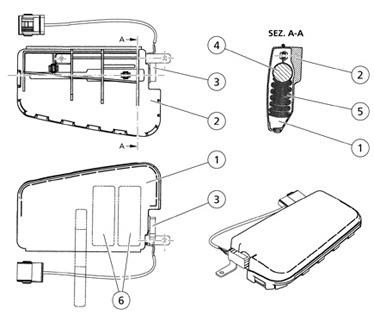
Seatbeltpretensioners
Quattroporte
The front and rear side belt winders are fitted with pyrotechnicpretensionersoperated by the airbag ECU, with a load limiting device.
Operation:
In response to the signal generated by the ECU:
•The gas generators’pyrotechnic charges (5) are set off.
•The pressure of the gas generates a force which pushes the rack piston (4) upwards.

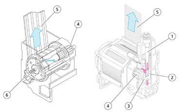
•The seat belt is wound in by a few centimetres.
1 Gearwheel
2 Gearwheel
3 Toothedbushing
4 Rackpiston
5 Pyrotechniccharge
6 Propellant
A Beforeactivation
B After activation
1 Gas generator
2 Piston
3 Rack
4 Beltwinder
5 Safetybelt
6 Torsionbar
IntroductiontoMaserati
8. ElectricalSystemsand Devices
Electronic vehicle architecture

Quattroporte
The electronic and electric functions of the various ECUsand nodes are controlled by the F.L.ORE.N.C.E system. The use of this new system, designed for CAN communication, has allowed Maserati to find immediate solutions as to communication, dimension, weight and cost problems. Each electronic control unit is positioned inthe barycentre with respect to the functions it controls, so that the system is fully optimised. The Quattroporte is the first Maserati model that employs the F.L.ORE.N.C.E. architecture.
The F.L.ORE.N.C.E. system is made up of two CAN communication networks:
• C-CAN network: dynamic control and management of the vehicle (high speed);
• B-CAN network: control of the standard bodywork functions (low speed).
The C-CAN and B-CAN networks are connected to each other by the body computer unit which is equipped with both the interfaces and hence performs the network GATEWAY function for transferring information.
The system also provides a number of serial lines used for diagnostics and other specific functions:
•K-line diagnostics for NCM / NFR / CSG / NCS / CAF
•Serial line W for immobilizer recovery
•A-BUS serial line for alarm, windscreen wiper and twilight sensor control.
Overviewof controllingmodules
Quattroporte
IntroductiontoMaserati
Diagnostics
SwitchMatrix cableharness
For use of the cable harness, it is essential that the key is turned to OFF when the SD3 is activated, until the ECU to be diagnosed has been selected. Thisis because in certain conditions, some errors may occur on the CAN lines, which would cause the warning lights on the instrument panel to flash.
ECU self-learning
Every time the battery is disconnected, a self-learningcycleis required in order to allow the correct operation of certain ECUs.
Motor-driventhrottle:
Turn the ignition switch to the ON position (Key ON) and wait for at least 30 seconds.
Central door locking system: Perform a lock/unlock operation with the remote control or the key. NIT (IT Info Node):
Reset the correct time and date using the specific NIT service menu
Sunroof:
The following initialisationprocedure must be carried out with sunroof closed and key ON:
•Rotate the selector switch fully, to the maximum tilting position (the part of the selector switch with three notches).
•Press the selector switch and, keeping it pressed, wait for the sunroof to lock mechanically.
•Releasethe selectorswitch.
•Within 5 seconds, press the selector switch again and keep it pressed.
•After a few seconds the sunroof will begin an automatic cycle (continue to keep the selector switch pressed).
•At the end of the movement, the initialisationis complete.
•Releasethe selectorswitch.