16 minute read
IntroductiontoMaserati


Post-catLambda monitoring:
The Lambda valuedown-stream of the catalyticconvertersismonitoredbyLSF type oxygensensors(two-levelsensors). TheseOxygensensorsare lessprecise thanLSU typesensors, and theyare utilisedprimarilyfordiagnosticpurposes. The Lambda valuedown-stream from the catalyticconvertersisusedto:
•Checkproperoperationof the catalyticconverters: In the eventof detection of low efficiencyof the catalyticconverters, the MotronicECU storesa DTC and illuminatesthe MIL warninglight.
•Checkproperoperationof the Oxygensensorsup-streamof the catalytic converters(plausibilitycheck).
•Providea minor contributiontothe FuelTrim.
Slow Down strategy:
•The catalyticconvertersmaybedamagedifthe temperature risesexcessively.
•A mathematicalmodel integratedin the ECU makesitpossibletocalculatedthe temperature of the catalyticconvertersin realtime.
•The parametersutilisedforthe calculationare asfollows: enginecoolant temperature, ambienttemperature, engineload, ignitionadvanceand Lambda value.
•The calculatedtemperature allowsthe ECU toprotectthe system fromserious problemsbyimplementingsuitablestrategies
•Whenthe calculatedtemperature reaches 980°C the Slow Down warninglight flasheson the dashboardtoalertthe driver tothe presenceof a criticalsituation.
•Whenthe calculatedtemperature reaches1040°C the Slow Down warninglight remainssteadilyilluminatedand the ECU switchesoff the engine. Highercatalytic convertertemperatureswoulddamagethe convertersand mayresultin a fire outbreak.
Exhaust system:
The exhaustsystem of the Quattroporte withdry sumpengine(Duoselect) iscomposedof the followingcomponents:
•Twoceramicpre-catalyticconverters, one per bank
•Two ceramic main catalytic converters
•Four Lambda sensors, two upstream (wide band) and two downstream(two level) of the pre-catalytic converters
•Centralpre-silencer
•Tworearsilencers
•Air-gaptechnology, externaldiameter: 75 mm, internaldiameter: 65mm
The system hasa specificdesign forUSA and Europespecifications. Withthe introduction of the Euro 4 anti pollutionstandard (fromMY06), the USA typeexhaustsystem wasused alsoforEuropespecificationvehicles. The Euro 4 configurationwasusedfrom MY06 in the marketswherenecessary.
Euro 4 markets:
•Europe
•USA
•Canada
•Hong Kong
•Singapore
•Korea
•Taiwan
Euro 3 markets:
•South America
•Middle East
•Japan
•Australia
•China
•Russia
•Philippines
•South Africa
•Malaysia
•Indonesia
USA and Euro 4 specifications:


Quattroporte Automatic(wetsumpengine):
Quattroporte
•Twomainmetal-core catalyticconverters
•Fouroxygensensors
•Centralpre-silencer
•Tworearsilencers
Forthe Quattroporte versionswitha wetsumpengine, the exhaustsystem isnewly designedforemissioncontrol. Modificationsmadetothe secondaryair system has allowedtoeliminate the pre-catalyticconverters. Catalytic converters in a single metal piece instead of the pre-catalytic converter solution upstream of the main catalytic converter.
The V8 is connected to an exhaust gas expulsion system which uses metal instead of ceramic catalytic converters: by means of a technology deriving from the racing world, the cell density is decreased, with consequent reduction of the section resistant to the gas flow and therefore less counter pressure upon exhaust.

2. Clutch
Quattroporte Duoselect:
All QuattroporteDuoselectmodels are fitted with a dry 215 mm twin-plate clutch. This solution significantly reduces the rotational inertia and consequently allows the engine to pick up speed more quickly. A contact-less position sensor continuously monitors the actual clutch position. See chapter 3 for more details.

•From assembly 18822 (SofastIII), a clutch actuator pressure sensor was applied.
•From assembly 21926 (SofstIII+), a new clutch with improved thermal inertia was introduced. This new clutch can be retrofitted on previous vehicles but such an operation includes replacement of the clutch housing.
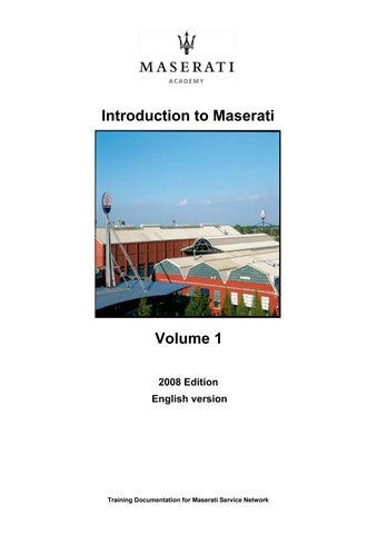
Quattroporte Automatic:
The Quattroporte Automaticisfittedwitha hydraulictorqueconverterwhichat the same time operatesasa drive-awayclutch. Seechapter3 formore details.
3. Transmission
The Maserati Quattroporte isavailablewithtodifferenttypesof transmission:
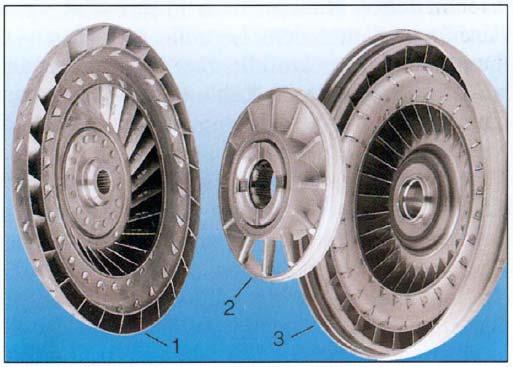
The Quattroporte Duoselecthasa transaxle configurationsimilartothe configurationof the M138 models. A robotizedmanual6-speed gearboxispositionedat the rearof the car whereitformsa sigle unitwiththe limitedslip differential. A twin-plateclutchismountedat the engineside. The propellorshaftislocatedinside a steel reactiontube whichformsa solidconnection betweenengineand gearbox.
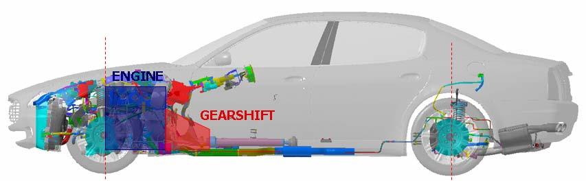
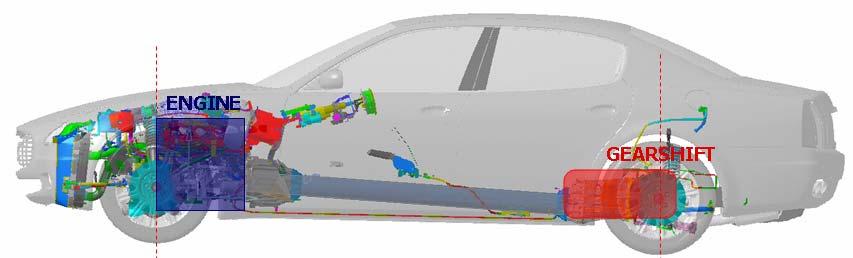
Fromthe beginningof 2007, the possibilityis offeredtocostumerstoenjoythe comfort of a traditionalautomatictransmissionin theirQuattroporte. The 6-speed automaticgearbox ismadebyZF and hasanadaptiveshiftstrategy. A new limitedslip differentialislocated at the rearside whilethe propellorshaftisof the composedtype.
The new powertrainconfigurationof the Quattroporte Automatichasalsoa certain influenceon the vehicle’s weightdistribution, witha weighttransfer fromthe reartothe front axleof approximately30kg. Total weightdistributionremainshowevernearlyperfect witha slightemphasison the rearaxle.
IntroductiontoMaserati
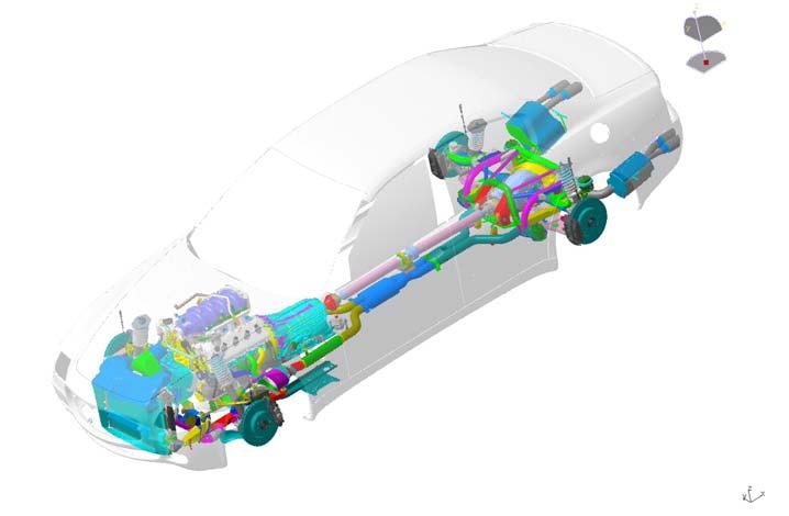
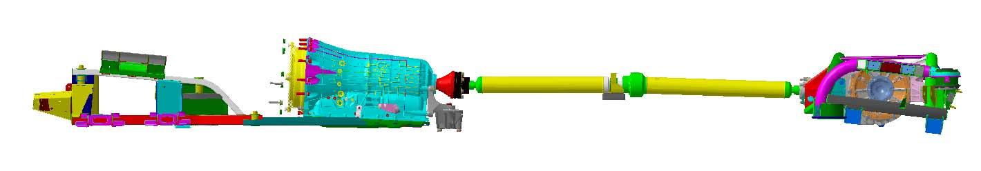
Quattroporte Duoselecttransmission

System layout:
Quattroporte
1.Steel reactiontube
2.Clutchhousing
3.Gearboxwithintegrateddifferential


4.Power unit
5.Hydraulicshiftactuator
6.High pressurelines
7.Gearboxoil cooler
IntroductiontoMaserati
Electronic gearboxcontrol
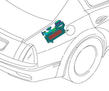
The transmissioncontrol unit(NCR –Nodo Cambio Robotizzato) islocated in the trunkcompartment, at the right handside.
System evolution:
Model launchEurope: SofastII (CFC 231)
Model lanchUSA (July’04): SofastIII (CFC301)
January’05 (fromassembly18822):SofastIII (allmarkets) longer6°gearforEU specifications
MY06 (fromassembly21926):SofastIII+(CFC 301)
Modifiedclutchwithincreasedthermalinertia Specificsoftware calibration longerfinal drive (4.18/1 insteadof 4.10/1)
Fromassembly24274: ABS/ESP Bosch 8.0 -eliminationof the specificaccelerationsensor
MY07 (fromassembly27860):No specificchanges
Seechapter3 formore detailsaboutthe varioussystem evolutions.
CAUTION!
In case of replacementor software updatingof engineor transmissioncontrol ECU’s, alwayscheckifthe correctsoftware versionisused. Itiscrucialthatenginesoftware and transmission software are matching. Note that transmissionsoftware isspecificfor variousmodel versions, model yearsand markets(EU –USA). Alwayscheckthe software versionbymeansof the vehicle assemblynumber.
Refertothe technicalpublicationsfromthe Maserati SAT departmenttoverifythe correctsoftware version.
Gearboxoperation
Gearbox operation strategies:
•‘Automatic’mode selected as default setting.
•When the key is in the ‘OFF’position, the 1st gear is selected.
•When the key is in the ‘ON’position, neutral is selected.
•In the ‘automatic’mode, the gear selected is not displayed on the instrument panel: only ‘drive’, ‘reverse gear’and ‘neutral’are indicated.
•When the engine is running, only the 1st gear, reverse gear or neutral can be selected.
•Newly designed reverse gear lever (with 1st gear engagement option).
•Gearbox controlled by means of closed loop logic.
•Newly designed gearbox ECU (NCR) is connected to the C-CAN line.
IntroductiontoMaserati
Low adherancemode (ICE): Whenthismode isselected, the vehiclestartsissecondgearand the enginespeedin eachgearwillbelimitedat 2900rpm.
Sport mode:
Ifthe “Sport”buttonispushed, the vehiclewill activatethe sport operationmode whilethe “SPORT”messagewillbeshownon the dashboard. Thiswillengagea more dynamic gearshiftstrategywithlaterupshifts. Ifsport mode and low adherancemode are selected at the sametime, low adherancemode willhavepreference.
Manualmode:
•Automatic mode is selected by default. Manual gearshift mode canbe requested by the driver with the A/M shift-button on the central console.
•By means of the controls on the steering wheel, the driver can select the gearshift (upshiftingor downshifting).
•Only the 1st gear or the reverse gear can be selected to start driving the car.
•When the Manual and Sport modes are selected at the same time, the system does not shift gears automatically when the maximum engine speed is reached.
Accousticsignals:
An accousticwarningsignalwillbe givenin the followingsituations:
When the reverse gear is engaged with key on and engine running. When you wish to park the vehicle in neutral (key on / neutral selected / key off). When automatic shift to neutral is signaled in the following conditions:
•Key on, engine running: if the accelerator and brake pedal are not pressed for at least 50 seconds.
•Key on, engine running: if the brake pedal is pressed for more than 10 minutes.
•Key on, engine running: If the door on the driver’s side is opened when the accelerator and brake pedal have not been pressed for at least 5seconds.
•During the ignition stage: If a gearbox malfunction has been detected.
IntroductiontoMaserati
Quattroporte automatictransmission
System layout:
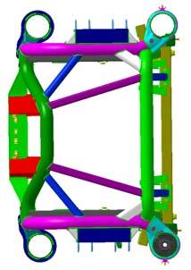
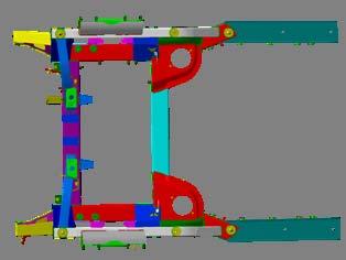
Quattroporte and modified to house this new
The QuattroporteAutomatic uses the ZF 6HP26 6-speed gearbox with hydraulic torque converter with integrated lock-up clutch. The engine/gearbox assembly is supported by a front subframewhich has been redesigned for this purpose.
The Quattroporte Automatichasa completelynew transmissionshaftwhichisof the composedtypeand usesthreeconstant-velocityjoints. Thissolutionwaschosenbecause of a notperfectalignmentbetweenthe gearboxoutput axisand the differentialinput axis. In case partsof the transmissionhavebeenremovedor replaced(gearbox, transmission shaft, differential), a shaftbalancingprocedure mustbeperformed. Thisistoavoidthe appearanceof vibrationsinside the passenger’s compartmentwhendrivingat highway speeds. Seechapter3 formore details.
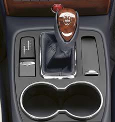
Gearshiftoperation
The automaticelectronically-controlledgearboxhassixforwardgearsand one reverse gear, in additiontoautomaticgearengagement, the driver can alsooptformanualgear engagement. The gearshiftlevercan beshiftedtothe followingpositions:
• P (park)
• R (reverse gear)
• N (neutral)
• D (drive)
• + / - (Manual)
The lever position is shown on the gear display by the illumination of the corresponding letter. This letter is also shown on the instrument panel display. The engine can only be started when the gearshift lever is in P or N.
WARNING: After starting the engine and setting off, do not depress the accelerator pedal before and while shifting the gearshift lever.This is particularly important when the engine is cold.
Shift-Lock
This safety system allows you to shift from P (PARK) to another position only if the release button on the gearshift lever and the brake pedal are depressed. This prevents the vehicle from involuntarily jumping forward or backward.
Key-Lock
This function allows you to remove the key from the ignition switch only when the gearshift lever is in P and within a maximum time of 30 seconds; when thistime has elapsed the key can no longer be removed from the ignition block. The gearshift lever can only be shifted from P when the ignition key is in MAR position and the button on the lever (A) and the brake pedal are depressed (Shift-Lock).
WARNING: In the case of an emergency, (e.g., breakdowns, battery flat, etc.) the ignition key can be removed even if the gearshift lever is not in P. To do this, turn the key to STOP, press the button F on the gearshift lever and at the same time remove the key.

Parking
When parking the vehicle, shift the lever to P. An integrated gearbox device will lock the rear wheels.
WARNING: To prevent accidental engagement, the gearshift lever can onlybe shifted from P to any other position when the button on the gearshift lever and the brake pedal are depressed.
WARNING: Shift the lever to position P only when the vehicle is stationary.
WARNING: Before getting out of the vehicle, check that the automatic parking brake is engaged. Shift the gearshift lever to P even when you need to get out of the vehicle for only a few seconds leaving the engine running.
WARNING: If you turn off the engine with the gearshift lever in a position different from P, an acoustic signal will sound for a few seconds.If the driver’s door is opened with the gearshift lever in a position different from P, an acoustic signal will sound for a few seconds.
CAUTION!
When parking on steep slopes, it is recommended to shift the lever to PARK before leaving the vehicle (whether the engine is running or not). This is recommended since the EPB system installed in the vehicle is capable of ensuring that the vehicle is properly parked and stationary when fully laden only on a gradient up to 20%
Automatic or Manual operating mode
The gearbox can be used both in fully automatic (position D) andin sequential manual (positions + or -) mode.The operating modes can be activated through the following selections:
• D Automaticgearshifting(AUTO)
• M (+ / -) Sequentialmanual gearshifting(MANUAL)
The lever can always be shifted between these two positions evenif the vehicle is moving and without depressing the brake pedal. The lever can continuously be shifted between D and M.
If automatic gearshift mode is selected, the word AUTO and the letter D will be shown on the instrument panel display, while for sequential manual gearshifting, the word MANUAL and the gear engaged will be shown.
Automaticoperatingmode
Select this position when you wish to use of all the automatic gearshift functions. With the vehicle stationary and the brake pedal depressed, shiftthe gearshift lever to D; if the gearshift lever is in P or R, also press the button A on thelever knob.
When the function is set, the letter D illuminates on the gear display and on the instrument panel.
With this function active, the ECU controls automatic engagementof the six gears. The gears will be engaged in relation to the travelling speed, engine RPM, accelerator position, speed with which the pedal is depressed, as well as the travelling conditions (uphill, downhill, curves).
The system is programmed to classify all driving styles related to the above mentioned parameters, matching them to ten different vehicle settings which go from extremely comfortable and fuel-economy driving to full racing-style driving. The setting is selected automatically.
Kick-downstrategy
This strategy is activated by rapidly and fully depressing the accelerator pedal, which causes engagement of a lower gear than the current one; this function assists the driver when maximum acceleration is required.When the pedal is released, the best gear in relation to the vehicle speed and the position of the accelerator pedal is automatically engaged.The kick-down strategy can be activated only when automatic operation has been set, with the gearshift lever in position D.
Strategiesfordownhilldriving
When the accelerator pedal is released and the transmission in “DRIVE”mode, the gearbox system detects that the vehicle is moving downhill and deactivates upshifting. When the accelerator pedal is depressed, upshifting is reactivated, however, with a delay of a few seconds.
When the brake pedal is depressed, the gearbox system downshiftsto provide enhanced engine braking power.
In other words, when driving downhill, the gearbox system operates so as to avoid upshiftingand shifting gears when the accelerator pedal is released, and delays gear engagement by a few seconds when the accelerator pedal is depressed. In addition, when the brakes are applied, it engages the lowest gear in order to provide enhanced engine braking power.
This strategy is aimed at making downhill driving safer.
Strategiesin curves
The system detects when the vehicle goes into a curve through the lateral acceleration and the steering angle. Detecting this condition with the “DRIVE”mode selected, the system deactivates both upshiftingand downshifting until the vehicle comes out of the curve. In particularly tight uphill curves the system downshifts. Gearshiftingis reactivated when the vehicle comes out of the curve at a distance that varies depending on the vehicle speed.
Manualoperatingmode
Down
Up
To engage the gears, move the gearshift lever to the following twopositions:
+ UP to engage a higher gear
-DOWN to engage a lower gear.
Gearshift paddles on the steering wheel (standard for the Sport GT, optional for other versions):in sequential manual operating mode, upshiftingand downshifting can be controlled not only with the gearshift lever but also with the two levers positioned behind the steering wheel. Also in automatic operation with the gearshift lever positioned in D (DRIVE), the driver can request a gear different from the current one by activating one of the levers. This action will temporarily switch the system to sequential manual operation. If the driver then keeps to a constant driving style (low longitudinal and lateral acceleration), the gearbox automatically switches back to automatic operation.
WARNING: Even if manual gearshiftingmode has been activated, some functions are still controlled automatically. When the engine is overrevvingor underrevving, the system automatically engages a higher or lower gear.
WARNING: If the driver requests a gearshift in conditions where the engine is overrevving or underrevving, the system will not accept the command.
WARNING: The electronic control unit is programmed to handle one gearshift at a time, therefore, fast and repeated requests will not necessarily result in a gearshift.The higher or lower gear is engaged only if the previous gearshift procedure has been completed.
Acousticsignals
If the engine is turned off with the gearshift lever in a position different from P, an acoustic signal will sound for a few seconds.
If the driver’s door is opened with the gearshift lever in a position different from P, an acoustic signal will sound for a few seconds. With the lever in R, the system emits an acoustic signal for a few seconds to warn anyone in the vicinity that you are about to reverse.
Adaptiveshiftstrategy(ASIS)
Resultingfromco-operationbetweenZF GetriebeGmbH, Robert Bosch GmbHand Maserati, a new software forelectronic transmissioncontrol hasbeendevelopped, containinga numberof usefullfunctions. The ASIS system goesmuchfurtherthana simpleadaptationof the gearshiftstrategyon the actualuphillor downhillroad gradient, as isusedbymostelectronically-controlledautomatictransmissions. Byincreasingthe interlinkingof the transmissioncontrol withothervehiclecontrol systems, suchasenginecontrol, brakes(ABS) and stabilitycontrol, a numberof signals are availablethatpermittodescribethe actualdrivingstatus. Byprocessing the information aboutlateral and longitudinalacceleration, enginespeed and torque, position and movementof the acceleratorpedal, steeringwheelangle, turning speedof the individualwheels, oil temperature,…a conclusioncan bedrawnaboutthe vehicle’s loadstatus and road topography, butalso aboutthe drivingstyle of the driver, whichisinfinitelyvariablebetweenverysporty (dynamic) and extremelyeconomicdriving. Theseinformationsare appliedtothe transmissionoperation. Thisfunctionisreferedtoas adaptivetransmissioncontrol. It recognisesthe driver’s intentions, takesnote of hisor her drivingstyle and adaptsitsselectionof gearsaccordingly. Manualinterventionbecomes thusunnecessary.
The ASIS functionscan bedividedin twogroups:
1) Evaluationof the drivingstyle and determinationof the type of driver: ASIS contains20 differentgearshiftmaps(10 forAuto Normalmode and 10 forAuto Sport mode). Foreach drivingmode the mostsuitablegearshiftmap ischosenaccordingtothe drivingstyle.
2) Selectionof the drivingmode accordingtothe drivingsituation, the topographical conditionsand the loadstatus: basedon the calculationof the road gradient, ASIS can choosebetween5 differentgearshiftmaps(one fordownhilldriving, one fordrivingon levelroadsand threegradationsof uphilldriving). The road gradientand vehicleload status can beestimatedbycomparingthe vehicle’s actualaccelerationwiththe theoretical accelerationgiventhe vehicle’s weight, selectedgearand enginetorque.
The ASIS adaptiveshiftstrategybasedon the drivingstyle comprehendsa long-term smoothingof the calculationof the driver’s drivingstyle in ordertobeabletoselectthe mostsuitablegearshiftmap.
Note: the ASIS adaptivememorycan bereset onlybyperformingthe cyclefunctionwith the SD3 diagnostictool. Thiscan benecessary, forexamplewhenthe vehicleissold toa new owner.
Note (2): the ASIS functionsdo notoperate ifthe ICE mode isselectedor ifdiagnosticor safetyfunctions(i.e. hot mode) are active.
Hot-mode strategy
In the event that the transmission oil or coolant temperature orboth are too high, the gearbox system reduces the maximum engine speed to 4000 RPM. Forthis reason, upshiftingwill occur at this limit. This strategy does not affect downhill driving, so as to always have the efficiency of engine braking together with the standard braking system.
Gearboxfailure
This message, highlighted in red, indicates a gearbox system failure, therefore, if you are travelling, the ECU that controls the device sets an emergency program. In these conditions, we recommended that you stop the vehicle and turn off the engine for at least one minute. When restarting the engine, the auto-diagnostic system may cancel the malfunction, which will in any case be recorded by the ECU. In failure conditions, the gearshift lever can however be shifted to R, N and D.When shifting to D, only a few gears will be available for shifting, depending on the malfunction found.
Automaticgearboxfailureindicationlight: depending on the message displayed it signals:
-a gearboxfailure
-a too high temperature of the gearbox oil.
Low gearboxoil levelindicationlight:
This icon indicates that the gearbox oil level is too low. If the warning light comes on, stop the vehicle. Check the gearbox oil level.
Gearshiftleveremergencyreleaseprocedure
In the event of failure of the electrical power supply system with resulting dead battery, the vehicle may only be moved after the gearshift lever has been released from the P position and moved to the N position. When there is no power, the lever can only be released using the emergency procedure.
•Remove the cover (A) in front of the gearshift lever.
•Using the screwdriver contained in the toolkit, push on the release mechanism through the holeand at the same time shift the gearshift lever to N.
•The gearshift lever has now been released.
NOTE: In order to tow the vehicle, the emergency release procedure of the EPB system must also be performed.
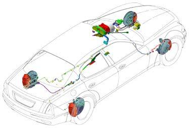
4. BrakingSystem
Characteristics:
•Hydraulicbrakecircuit, X-separated(steel flexiblebrakelineson Sport GT)
•15/16”master brakecylinderwith18+18 mm stroke
•VacuumbrakeassistanceØ8 + 9”, control ratio of 13.5
•Ventilatedfront discs, 330 x 32 mm (cross-drilledon Sport GT)
•Front brakecaliperswith4 pistons
•Ventilatedreardiscs, 316 x 28 mm (cross-drilledon Sport GT)
•Rearbrakecaliperswith2 pistons
•Drumparking brake, integratedin rearbrakediscs
•ABS / stabilitycontrol Bosch 5.7 containingthe followingfunctions: ABS, EBD, ASR, ESP, and MSR
Upgrades:
•Adaptionof the new Bosch ESP 8.0 ABS / stabilitycontrol system (fromassembly 24275 onwards)
•upgradedrearbrakes: 330 x 28 ventilateddiscsand 4 pistoncalipers(fromMY07 onwards)
•Adaptionof anelectricallyoperatedparking brake(EPB) forthe Quattroporte Automatic.
•Adoptionof the PreReleasefunctionof the EPB system forQuattroporte Automatic forMY08 (assembly34071 onwards)
•New revolutionarydual-castventilatedfront brakediscswithincreaseddiameter (360mm) and sixpistoncalipersfor the Quattroporte Sport GT S
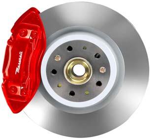
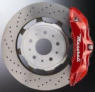
Dual-castbrakingsystem
Forthe Quattroporte Sport GT S, a new revolutionarybrakingsystem hasbeendeveloped in collaborationwithBrembo. Thisinnovative technologyusesdual-castbrakediscs(cast ironand aluminium) forthe front brakes. It isthe first time sucha technologyhasbeen employedon a road car.
Thisnew technology, togetherwiththe largerdisc diameter(360 mm) and new 6-piston calipersmakesfromthe Quattroporte Sport GT S one of the fasteststoppingroad cars (from100 km/h tostandstillin little more than35 m), whileitsreducedunsprungweight offersimportantbenefitsin termsof comfort and drivingprecision.
Note: the rearbrakesare identicaltothosefromthe Quattroporte Sport GT.
1) Cast ironfrictionring
2) Aluminiumcentralpart
The co-cast or dual-cast floating brake disc is made of two materials, cast iron and aluminium. This new disc has many advantages: reduced weight (15% lighter), greater driving comfort, less corrosion, less wear and better brake performance.
The co-cast floating brake disc has a cast-iron braking surface and an aluminium hat: ideally combining the advantages of heat-resistance and excellent friction characteristics provided by cast iron with the lightweight properties of aluminium. The innovation is in the way the two materials have been combined to a single component, and in the behaviour of the disc during operation, functioning effectively as an integral disc at low temperatures, then as a floating disc at high temperatures, when maximum performance is needed and distortion tends to occur.
Unlike an integral disc, the co-cast brake disc presents a symmetrical braking surface, favouring a more uniform temperature distribution when the brakes are applied: this means considerably less residual deformation after the brake is released (–70%). This effectively emulates the performance capabilities of a floating disc, but without the number of components needed for a floating assembly.
MSP (Maserati StabilityProgram)
The MSP system (Bosch ABS/ESP 5.7) integrates the following functions:
• ABS (Anti-lock Brake System): This system prevents the wheels from locking during hard braking or braking under low adherence conditions. ABS guarantees the controllability of the vehicle under braking conditions (controlof the longitudinal stability of the vehicle).
• EBD (Electronic Brake force Distribution): Electronic distribution of the brake force between front and rear axle.
• ASR (Anti Slip Regulation): Traction control.This systems prevents the driven wheels (rear wheels) from spinning during acceleration, improving traction in low-grip conditions. For this function, MSP interacts with the engine control system.
• MSR (Motor SchleppmomentRegelung): Electronic control of the engine brake torque under downshift conditions. This system prevents the rearwheels from locking under downshift conditions due to the high engine brake torque and thus guarantees the vehicle’s stability. Also this system interacts with the engine control system.

• ESP (Electronic Stability Program): This system monitors the vehicle’s stability during cornering. ESP can apply the four brakes independently tobring the vehicle back on track if a dangerous situation for the vehicle’s stability is detected (control of the lateral stability of the vehicle).
• Hill Holder (from ABS/ESP 8.0): this function will prevent the vehicle of moving backwards during uphill departing.
Instrumentsand controls:
IntroductiontoMaserati
MSP operationlogic:
NORMAL mode
This mode provides maximum grip and the risks related to the most diverse driving conditions are reduced. This offers the driver an invisible "safety guard", for any driving style. If losing grip or in the event of skidding, the system operates in a targeted way braking one or more wheels, thus allowing the driver to fully control the vehicle. The operation is accurately performed without involving the driver. In this way, the vehicle will continue to move in the desired direction without taking accountof the action on the accelerator pedal or the input transmitted to the braking systemby the driver, whatever the road conditions.
SPORT mode
This is the second option provided by the management system. When this mode is set, the system will continue to provide the driver with an electronic protection system that is capable of correcting possible critical situations, but at the same time it will offer more demanding drivers enhanced driving freedom. For example, the vehicle is allowed to slide sideways until reaching an angle of six degrees so as to offer the driver a sufficient handling margin to express his vehicle control skills. This modealso offers the driver the opportunity to explore the limits of the vehicle in full safety.
MSP OFF mode
If the vehicle is driven under "extreme" conditions, the ESP, ASR and MSR systems can be fully deactivated by the driver. The vehicle will perform without any safety system and the driver will have to rely only on the vehicle and his driving skills for particularly exciting driving. Even if the control system is deactivated, ABS and EBD will remain active to prevent wheels from locking.
MSP OFF is also the applicable driving mode in case snow chains are installed.
Low Adherancemode (ICE)
This mode can be used on particularly slippery road surfaces (e.g., snow, ice) and it is activated/deactivated by pressing the button on the NIT. The word ICE will illuminate on the instrument panel display. In “Low-grip" mode the system uses 2nd instead of 1st gear. This means that when y start from a stationary position with theengine running -both in automatic mode and manual mode -the vehicle will start in 2nd gear. When sequential manual mode is selected with 2nd gear engaged, a downshift request will be ignored. While driving, the system automatically switches to the upper gear if the engine reaches the pre-established speed rate (3,000 RPM). “Low-grip" mode has priority over SPORT mode and assists the MSP system.
If “ICE”mode is activated when “SPORT”mode is active, during the transition stage it may happen that both the “ICE”and the “SPORT”messages are present on the CAN line. In this case, the system will give priority to the “ICE”message, immediately showing it on the display.