2 minute read
Oil and grease specification


5- Tools
5.1 Super Seal connectors
fif
5.4 Grease guns Figur
24981
A tool with a pointed nozzle used to apply grease. Length 170 mm.
755132 Single-hand grease gun with straight discharge pipe and nozzle.
755142 Two-hand grease gun with angled discharge pipe and nozzle.
755152
Two-hand grease gun with hose and nozzle.
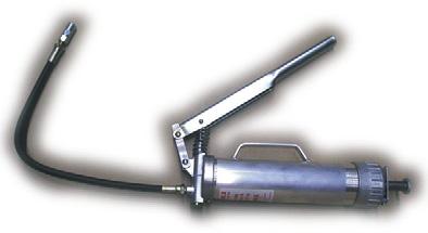

755146 Grease hose 450 mm. Grease hose 750 mm. Grease hose 1500 mm.

202154PM
Pointed nozzle for grease guns used to apply grease in recessed nipples. Fits grease guns with hose and discharge pipe. Length 125 mm.

755140 Nozzle for neck nipples. Fits grease guns with hose and discharge pipe.
5.5 Other tools

207881
Hand terminal for communication with the transistor regulator. Needed for the following uses:
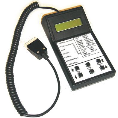
•Changing parameters.
•Uploading and downloading parameter settings.
•Display of error messages.
•Calibration.
Chassis - 0000
Support arms SP10
6- Chassis - 0000
6.1 Support arms SP10
If the bolt joint between the chassis and the support arms are to be adjusted or if the support arms are to be replaced, the bolts must be replaced with new ones. Two guides (4) should be at both position 1 and 2. Tightening is done first to 20 Nm of torque at 1 and 2 in order. Then full tightening is done in the same order to 200 Nm of torque. Finally position 3 is tightened to 200 Nm of torque.
Chassis - 0000
Support arms SP10
6.1.1 Placement of supportarms
Same supportarm can be used for different width. Check for correct measure between supportarms. To do that, check the marking for each supportarm according to the table below:
Support arms SP10S
6.2 Support arms SP10S
6.2.1 General
The truck is composed of a unit assembled so that the support arm chassis and the separate assembly points for the mast and the support arms are screwed onto the drive section.
The support arms on the support arm chassis are adjustable for different interior support arm widths from 900 mm to 1300 mm to accommodate different pallet sizes. Normally, the support arm width is only adjusted prior to delivery to a customer.
6.2.2 Main Components
6.2.3 Maintenance
If the bolt joint between the chassis and the support arms are to be adjusted or if the support arms are to be replaced, the bolts must be replaced withnew ones. Tightening of the clamp bolts (3) is done using a torque wrench set at 220 Nm.
6.2.4 Adjusting the support arm width
To adjust the distance between the support arms, proceed as follows:
•Lift up one side of the truck.
WARNING !
The truck can tip over. Do not lift up both support arms at the same time. Lift one side at a time and support it while you work.
•Loosen the locking nut and the locking screw (4) on the front of the cross bar.
•Loosen the screws and nuts of the clamp (3).
•Adjust the support arm, ensuring that the setting is the same on both sides.
•Tighten the lock.
•Insert new screws and nuts and tighten them loosely (crosswise) using a spanner.
•Loosen the lock slightly and then tighten the nuts to 220+/-12 Nm.
Chassis - 0000
Support arms SP10S
6.2.5 Replacing support arms
Replacing a support arm is a more extensive task than adjusting the width
•Lift out the battery.
•Lift up the side of the truck where the support arm is to be replaced.
•Loosen the locking bolt on the front of the cross bar (4).
•Loosen the bolts of the clamp (3).
•Pull out the support arm.
•Install the new support arm and adjust the width as per the chapter “Adjusting the support arm width”.
•Lower the truck to the floor.
•Lift in the battery.