11 minute read
Priority Valve


1. When the steering wheel is turned right until the steering cylinder reaches the end of its stroke, a further attempt to rotate the steering wheel causes the steering relief valve to open to relieve the pressure.
In this case, the oil flows through the following route.
Port CF → Orifice Cdy → Pressure chamber B → Filter → Steering relief valve → Tank
2. Under this condition, the pressure loss as the oil passes through orifice Cdy result in a pressure difference between chambers A and B, causing the spool to move to the right end. Therefore, almost all the amount of oil except the one flowing from the relief valve is available for use by the other actuator circuits.
Priority Valve
3. Troubleshooting
The problems which can generally be experienced with the priority valve are listed below with their possible causes and recommended measures to be taken.
These problems, however, may result from causes not shown here and require other measures to be taken.
Problem Cause Remedy
Hard steering
1. Dust caught in relief valve Disassemble, clean, and reassemble.
2. Spool stuck (by dust) Disassemble, clean and reassemble, or replace.
3. Orifices in plug and spool clogged Disassemble, clean and reassemble.
2. Too low control pressure Readjust control pressure. (Hard steering with engine at low idle)
Abnormal sound
1. Insufficient pump delivery rate Check pump.
3. CF piping resistance excessive Replace piping.
1. Dust caught in relief valve Disassemble, clean and reassembly.
2. Spool stuck (by dust) Disassemble, clean and reassemble, or replace.
Oil leakage
1. Insufficient plug tightening torque Retighten to specified torque.
2. Damaged O-ring Replace.
Priority Valve
4. Disassembly
Caution
Remove the dirt, dust, water, etc. from the valve surfaces prior to disassembly, taking care not to let them enter the valve.
Cleanliness is essential for disassembly and reassembly of the valve. Keep clean the work place.
1. Hold housing(1) in a vise. Use cushioning copper plates to protect the housing and avoid tightening the vise excessively.
2. Remove plug(2) for port LS and remove spring(4) and spool assy(5). Then remove plug(9). Set screw(7)(orifice Cdy) and set screw(8)(orifice Cpp) cannot be disassembled, as they are fixed in spool assy(5).
3. Remove relief valve assy(10) from port T. Valbe seat(14), screen(13), ring(12) and adjuster(15) cannot be disassembled, as they are fixed in body(11).
Priority Valve
5. Cleaning
1. Clean all the metallic parts in a clean kerosine and blow compressed air to dry them.
2. Do not grind the parts with a file or polish them with a coarse emery paper.
3. Replace all O-rings with new ones and apply grease to the O-rings.
6. Reassembly
1. Hold housing(1) in a vise. Use cushioning copper plates to protect the housing(1) and avoid tightening the vise excessively.
2. Screw the assembled relief valve assy(10) into port T of housing(1).
Tightening torque: 21N-m {15.5ft-lbf}
3. Install spool assy(5) in port LS of housing(1).
[NOTICE]
Make sure that the direction of the spool is correct. Check that the spool moves smoothly when pressed by finger.
4. Insert spring(4) from port LS side of housing.
5. Fit O-rings on plugs(2) and (9).
Screw plug•a into port LS in housing and plug(9) into the opposite end of the housing.
Tightening torque: 21N•m { 15.5ft•lbf } (both plugs)
The above completes the reassembly of the priority valve.
S-3 Orbitrol
1. Structure and functions
The orbitrol is a load sensing, dynamic signalling type oil passage switching device. It is consists of the following major components.
1.1 Housing
The housing has five piping ports, P, T, R, L and LS.
[NOTICE]
There is a case that the appearance and so on differ from the parts for this machine. Although there is not so much difference in functions and disassembly procedures, make sure of the serial number of this machine and the part sales unit described in the parts catalog before starting disassembling operations.
Thread size and tightening torque
Thread size and tightening
1.2 Spool and sleeve
1. Spool is splined to the steering wheel. When the spool turns as the steering wheel is roted, its position relative to sleeve changes, and the oil passage is switched as a result.
2. A total of three different oil passages are available from the spool and sleeve combination. Spool and sleeve are mechanically connected in two places as shown in Section C-C and D-D.
4. In the section corresponding to View D-D, spool, sleeve and drive are connected together by pin without clearance, whereas spool has slots that allow it to move on pin within a certain angle.
5. This configuration allowing spool to change its position relative to sleeve make it possible for the orbitrol to provide the three valve positional states as shown in the figure.
1.3 Drive
The drive transmits the movement of the star of rotor set via pin to sleeve.
3. In the section shown in Section C-C, springs are fitted in the slots in both spool and sleeve. When the steering wheel is in neutral position, the positional relationship between spool and sleeve is maintained in the state shown in Section C-C by action of springs.
The rotor set consists of a ring with seven internal teeth and a star with six teeth (one tooth less than the teeth of the ring), which is in mesh with the ring.
2. Operation
The orbitrol operates interacting with the priority valve. This section describes the operation of the orbitrol itself. For information on the interaction between the orbitrol and the priority valve, refer to the “Priority Valve” section.
2.1 Neutral state
The pressure oil that has entered port LS flows through the passages in the sleeve and spool into the cavity in the spool and goes through the grooves of the spool and sleeve to port T.
High pressure oil from pump
Delivery oil
Return oil
Neutral or trapped
2.2 Right steering
1. When the steering wheel is turned clockwise the spool shifts clockwise with respect to the sleeve to provide the valve positional states shown in the figure.
flowrate), and the pressure reflecting the orifice area change is guided from port LS to the priority valve for use as a signal pressure to control the oil distribution by the priority valve.
4. When the pressure oil enters a tooth space, the star is rotated in the same direction that the spool has moved so that the tooth space volume expands. Rotation of the star forces the oil in three tooth spaces (on the delivery side) to go through the oil hole in the housing, the hole of the sleeve, the groove in the spool, the hole in the sleeve, and the R port in that order and then flow into steering cylinder.
2. As a result, the pressure oil from port P does not flow into the cavity of the spool but goes through the hole in the sleeve, groove in the spool, hole in the sleeve and three of the seven oil passages in the housing to the three spaces formed by the star and ring teeth of the rotor set.
5. The oil forced out from the steering cylinder enters the L port, passes through the hole in the sleeve, the groove in the spool and the hole in the sleeve, and then returns to the T port.
6. When the star is rotated, the spline-connected drive is rotated, and the sleeve is also rotated via the pin. When the star is rotated by the pressure oil, therefore, the sleeve moves such that the displacement of the spool with respect to the sleeve is cancelled out.
3. The flowrate of the oil to port P is determined by orifice C1 in the orbitrol. Orifice C1 is provided for obtaining a pressure signal for actuating the spool of the priority valve. The orifice area varies with the steering wheel operating speed (steering
7. In other words, the sleeve moves in such a way as to follow up the displacement of the spool and continues to do so whole the steering wheel is being rotated. So the oil is continuously delivered to the R or L port.
2.3 Steering wheel turned left
High pressure oil from pump
Delivery oil
Return oil
Neutral or trapped
3. Disassembly
3.1 Rotor section
1. Lightly hold the mounting flange of the unit in a vise, the rotor side up. Use cushioning copper plates to protect the unit and avoid applying excessive force.
5. Remove O-ring from end cap.
6. Remove rotor set taking care not to allow the star in the rotor set to fall.
O-ring Star
IW184-0020E12 Spacer Rotor set
7. Remove O-ring and spacers and from rotor set.
8. Remove drive, plate and O-ring.
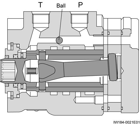
2. Remove bolts by using a 5/16”, 12-point socket wrench.
3. Remove ball from housing.
4. Remove end cap.
IW184-0020E11 O-ring End cap Bolt
Plate O-ring Drive
3.2 Control section
1. Remove housing from the vise, and place it on a clean cloth, while taking care not to give damage to the finished surface. Using a small screwdriver, raise an end of snap ring to remove the snap ring from housing.
6. Remove the spool and sleeve assembly from housing by pulling it in the opposite direction to the flange.
2. Rotate spool and sleeve to place pin in a horizontal position. Press spool and sleeve with the thumb to remove bushing from housing.
Oil seal Dust seal Bushing
3. Remove oil seal from bushing.
4. Remove dust seal from bushing by using a screwdriver. Take care not to damage bushing.
5. Remove bearing race and bearing.
7. Remove pin from the spool and sleeve assembly.
8. While pushing spool in sleeve slightly forward, carefully remove springs from spool by hand. Remove spool by slowly rotating and pulling it toward the rear of sleeve.
9. Remove O-ring from housing.
Bearing
Bearing race Bearing race
[NOTICE]
Remove the spool and sleeve assembly while slowly turning it in both directions to prevent the assembly from wedging in the housing.
4. Check
1. Check all the parts for matching surface condition. Scratched or burred parts should be replaced, as they could cause oil leaks. Clean all metallic parts in a clean kerosine and dry them with compressed air.
2. Avoid wiping the parts with a piece of cloth or paper, as lints remaining in the unit could contaminate the hydraulic system and cause functional problems. Never File or sand the parts.
3. Replace all the rubber parts with new ones, and apply grease sparingly to the O-rings.
5. Reassembly
5.1 Control section
1. Slide spool into sleeve while rotating and align their spring grooves. After assembling them, lightly hold the spline section of spool between fingers and check that it turns lightly in sleeve Some spool and sleeve sets have alignment marks. Line up the marks for such a set.
2. Place the assembled spool and sleeve upright on a flat surface, with their spring grooves aligned. To set springs in the inserting tool, place two sets of three springs back to back with the notches at both ends downward. Using spring inserting tool, fit springs in the spring grooves of both parts Raising spool slightly in sleeve will facilitates the job. IW184-002022
3. Pinch springs by fingers, and push the springs into the spring grooves in spool and sleeve while pulling the inserting tool back at the same speed.
4. After springs have been fitted in the center of spool and sleeve, line up the springs with the ends of the spool and sleeve.
5. Insert pin into the holes of spool and sleeve and adjust the position of the pin so that its both ends will be flush with the outside surface of the sleeve.
Pin
[NOTICE]
Insert the spool and sleeve assy into the housing taking sufficient care not to let it tilt and wedge in the housing. When inserting the assembly, rotate it a small amount in both directions repeatedly while maintaining pin in a level position. Be sure to insert the assembly until its rear end is flush with that of the housing, but never exceed that position. If the assembly is inserted further, the pin might drop.
After the assembly has been inserted to the correct position, make sure that it lightly rotates in the housing.
6. Insert the spool and sleeve assy into housing from its rear end.
7. Place housing on a clean flat surface and install O-ring, bearing race and bearing.
10. Fit bushing on spool while rotating the bushing. Then tap bushing with a plastic hammer down into position.
Driver Dust seal
Snap ring
Bushing
Oil seal
O-ring
11. Fit snap ring in housing, and expand the snap ring by pressing its inside diameter so that it will securely fit in the groove.
8. Fit dust seal on bushing, with its flat side in contact with the bushing.
9. Install oil seal on bushing by pressing down by finger.
5.2 Rotor section
[NOTICE]
Make sure that the spool and sleeve assembly is slightly indented from the end surface with the 14 holes of housing.
Wipe clean the end surface of the housing with a clean hand palm.
The matching surfaces of plate and rotor set should also be cleaned with a clean hand palm. Avoid using a piece of cloth or paper.
1. Hold the flange of housing lightly in a vise.
2. Fit O-ring in housing.
3. Place plate on housing and line up the bolt holes with the threaded holes in the housing.
4. Rotate the spool and sleeve assembly so that pin will be in parallel with the port end surface of housing.
Insert drive into the housing while engaging its yoke with the pin. To ensure correct positioning, draw a line beforehand with a felt pen on the spline end surface of the drive as shown in the figure.
Port end surface Drive Pin
Pin should be parallel with port end surface
5. Install O-ring on rotor set.
[NOTICE]
Check that lines A, B, C and D are in parallel with one another as shown in the figure.
6. Fit rotor set on drive with the O-ring side of the rotor set toward plate, while lining up the line across tooth roots of the star (A) with the previously marked line on drive (B).
Roots of star teeth
Drive Pin (Draw a line)
Port end
IW184-0020E29
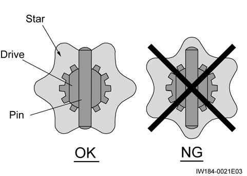
7. The position of star and the drive side pin is as shown in the following figure.
11.Place end cap on rotor set and line up the bolt holes.
[NOTICE]
This procedure is of vital importance in determining the valve timing of the unit.
8. While maintaining the drive and star engagement, line up the bolt holes in the rotor set and those in the plate and housing.
9. Install spacers in rotor set.
[NOTICE]
Fit the steering wheel in the spool and check that the spool rotates.
12.Apply oil to the threads of bolts and fit the bolts in end cap. First tighten the seven bolts to approx. 14.7(10.8ft-lbt) and then tighten them to 22.6N•m(16.7ft-lbt) in the sequence shown below.
Steering Cylinder
S-4 Steering Cylinder [NOTICE]
There is a case that the appearance and so on differ from the parts for this machine. Although there is not so much difference in functions and disassembly procedures, make sure of the serial number of this machine and the part sales unit described in the parts catalog before starting disassembling operations.
*1:
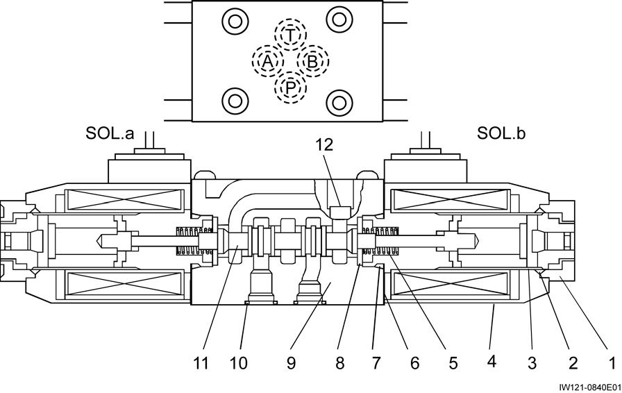
Solenoid Valve (Steering Mode)
S-5 Solenoid Valve (Steering Mode)
[NOTICE]
There is a case that the appearance and so on differ from the parts for this machine. Although there is not so much difference in functions and disassembly procedures, make sure of the serial number of this machine and the part sales unit described in the parts catalog before starting disassembling operations.
Solenoid valve assy (SoL.32)
Connector
-
IW121-0542E01
Solenoid Valve (Steering Mode)
(+) : Red
(-) : Black
IW121-032002
[NOTICE]
Adjust the flute at the end of spool(9) to plug(13) side. Adjust the slit of centering washer(10) to body(7) side.
Thread size and tightening torque
Solenoid Valve (Steering Mode)
Solenoid valve assy (SoL.30, 31)
(+) : Red (-) : Black
[NOTICE]
Spool(11) is symmetric. Adjust the slit of centering washer(8) to body(9) side.
Thread size and tightening torque
Solenoid valve assy (SoL.33)
Solenoid Valve (Steering Mode)
(+) : Red
(-) : Black
[NOTICE]
Adjust the flute at the end of spool(9) to plug(13) side. Adjust the slit of centering washer(10) to body(7) side.
Thread size and tightening torque
Tightening torque

