20 minute read
Air Dryer


1. The pressurized air from the air dryer outlet port (air tank pressurized air) travels through the passage and acts on the bottom of the governor piston.
2. When the air pressure is at or below the specified pressure, the governor piston is kept pressed down by the spring.
3. Under these conditions, the pressurized air in the control port passes through the exhaust stem and is released into the atmosphere.
2.4 Release position
1. When the outlet port air pressure (air tank air pressure) increases, and the force acting on the bottom of the governor piston becomes stronger than the force of the spring, the governor piston moves toward the spring side.
2. The exhaust stem is closed by the governor valve, and the control port air is cut off from the atmosphere.
3. When the outlet port pressure increases further, and reaches the release pressure, the governor piston moves farther to the spring side, and the governor valve is opened by the exhaust stem.
4. The pressurized air from the outlet port passes through the governor valve, and is delivered from the control port to the top of the air dryer drain valve, pressing the drain valve open.
IW232-0030E08
IW232-0030E09
5. The outlet port air pressure (air tank air pressure) gradually decreases. When it drops to the intake pressure, the governor piston is pressed back by the spring.
6. This closes the governor valve. The exhaust stem is disconnected from the governor valve, and the control port pressurized air passes through the exhaust stem to be released into the atmosphere. This closes the drain valve.
3. Precautions for handling [NOTICE]
Be certain to use the desiccant specified by NABCO (part No. 41213640010), and replace it with an amount that is within the specified range. Use of a desiccant other than that specified, or in amounts less than those specified, will not only reduce the moisture-absorption capability of the dryer, but can lead to degradation and loss of the desiccant and can greatly increase the likelihood of vehicle malfunctions.
Be aware that the desiccant used in DU-3 is of a different type than the desiccant used in DR-41, DR-42, and DU-4.
Be sure to perform tapping when inserting the desiccant.
1. If the vehicle has been parked for several hours in a cold location (-10 C (14 F) or below), wait at least 10 minutes before driving after starting the engine. (It takes time for the temperature to rise after the heater turns ON.)
2. Make sure that the unload time is 50 seconds or longer.
(If the regeneration process is not performed, the moisture-removal capability of the desiccant is decreased, and the dryer function is lost.)
3. During unloading, air is continuously discharged from the air dryer exhaust port. This is normal, and is not a problem of air leakage.
4. Replace the desiccant every 1 year or 100,000 km (62140mi) of travel, whichever occurs sooner.
5. If drainage occurs from the air tank, disassemble the dryer, and replace the desiccant if 1/5 or more of the total desiccant is seeped in oil. (If the desiccant becomes seeped in oil, its ability to absorb moisture is decreased. Because this greatly affects dryer function, be sure to replace the desiccant if this occurs.)
4. Maintenance and inspections
Warning
When performing inspections, use caution to prevent dirt from entering the eyes.
4.1 Daily inspection
1. Check for air leakage around the body, at pipe openings, and other locations.
2. To check that the air dryer is operating normally, open the drain cock on the air tank, and check that there is no drainage. (A small amount of drainage may accumulate if the temperature around the air tank has decreased by more than 17 C (62.6 F)).
3. In cases other than the above (drainage resulting from temperature change), if a small amount of drainage occurs, check the precautions for handling again.
[NOTICE]
If the desiccant becomes seeped in oil or other substance, its ability to absorb moisture is decreased. Because this greatly affects dryer function, be sure to replace the desiccant if this occurs.
It is recommended that you replace the filter at the same time as the desiccant.
4. If no abnormalities are found, disassemble the air dryer and check whether or not the desiccant is seeped in oil or other impurities. If 1/5 or more of the total desiccant is seeped in such substances, replace the desiccant.
[NOTICE]
◆ Oil (liquid oil and carbonized oil) is contained in the compressed air that enters the air dryer. This will accumulate in the compressor and dryer piping, and inside the dryer itself. Because this oil may burn, be sure to perform cleaning periodically.
5. Pay attention to the drainage from the air dryer exhaust port. If an abnormal amount of oil is drained, inspect the compressor and take steps to prevent increases in the amount of oil.
Air Dryer
6. Use the on-board air pressure gauge to check that the pressure governor is operating at the specified pressure. Also check that there is no decrease in pressure when the brakes are not in use.
Governor switching pressure:
Refer to ìPressure regulatorî in ìAir puressure setting tableî in chapter Y.
4.2 Inspection and part replacement every 1 year or 100,000 km (62140mi) of driving
1. Disassemble the air dryer. Replace the desiccant, oil filter, filter, and all rubber parts, regardless of whether or not scratches or wear is visible on these parts.
2. Check that there are no abnormalities in the piping and wiring.
[NOTICE]
Corrosion of metal parts can result in air leakage when the corrosion falls off and becomes caught in the valves.
These inspections and maintenance are to be performed when either the travel distance or installation time is reached, whichever occurs first.
3. Check all metal parts for corrosion. Repair or replace them as necessary.
5. Disassembly
5.1 Removing DU-3
1. Block the wheels without using the pneumatic circuit.
2. Open the drain cock on the air tank. Discharge the air from the brake piping.
3. Disconnect the thermostat wiring.
4. Disconnect all the wires (IN, OUT, CONTROL) from the air dryer.
5. Loosen the three bolts to remove the UD-3.
5.2 Disassembly of cartridge
1. Anchor the DU-3 body-1 in a vise. Unscrew the bolts and washers that fasten the purge chamber to the body, and remove the purge chamber.
2. When the purge chamber is removed, cartridge assy through containing the desiccant is exposed. Directly remove the cartridge assy upward by hand.
Caution
Keep pressing on the case cover with your hand until all screws and washers have been removed.
The case cover can be extremely dangerous if the set spring inside causes the cover to jump up and strike a person in the face or other body part.
3. Use your hand and press from above on the case cover attached to the desiccant case. At the same time, use a Phillips screwdriver to unscrew and remove the 4 screws and washers.
4. Remove set spring, filter plate B, filter, desiccant, filter and filter plate A from above the case.
Set spring
Filter plate B
Filter plate A
Case cover Set spring Screw and Washer
Purge chamber Bolt and Washer
Purge chamber Desiccant
Body
IW232-0011E12
Filter
Purge chamber Absorbent Filter
6. Press the cover with your hand, and lift the case up to remove it. Remove the oil separator filter that is inside.
IW232-0030E11
5. Use a 4 mm hex wrench to unscrew and remove the 4 hexagon socket head bolts and washers.
6. Reassembly [NOTICE]
With the exception of rubber parts and the desiccant, wash all disassembled parts well with clean oil and wipe off all adhering substances.
Warning
Be certain to use the specified NABCO desiccant (41213640010).
Use of a desiccant other than that specified is extremely dangerous. It can result in the desiccant deteriorating and being lost, with pieces blocking the brake piping and preventing normal brake operation.
The desiccant used is different than that used for NABCO DR-41, DR-42, and DU-4. Be careful not to use the wrong type.
6.1 Cartridge (lower)
1. Install the oil separator filter in the center of the cover, and install the O-ring into the groove.
3. Insert filter plate A and the filter into the case. Insert the filter so that the soft surface is on top.
soket
4. Insert the specified amount of desiccant. The specified amount is 590 - 619 cm3 (3637.8in3) [480g (1.06lb)]. Insert the entire bag of desiccant that was purchased for use with the repair kit.
DANGER
If less than the specified amount of desiccant is used, the desiccant may deteriorate and be lost, with pieces blocking the brake piping and preventing normal brake operation. Be sure to insert the specified amount.
5. Next insert the second filter, this time with the soft surface on the bottom. Then place filter plate B in position and perform tapping.
2. Place the case in position, and use a 4 mm hex wrench to tighten the hexagon socket head bolts and washers.
Tightening torque: 2.0 - 3.9 N-m (1.5 - 2.9 ft-lbf)
6.2 Tapping
Danger
When tapping is not performed, the desiccant may deteriorate and be lost, with pieces blocking the brake piping and preventing normal brake operation.
Be sure to follow the procedure below when performing tapping.
[NOTICE]
When tapping, place 2, 3 sheets of shopcloth or other soft cloth on top of one another at the tapping location to prevent the cover from being scratched.
6.3 Cartridge (upper)
[NOTICE]
Applying grease to the raised part of the check valve will allow it to be inserted more easily. Use NABCO grease (grease pack 45499030090, grease weight: approximately 10 g (0.022lb).
1. Fit the check valve into the case cover by pressing on the center bulge with your thumb.
2. Install the O-ring onto the case, then insert the set spring. Tighten the screws and washers while pressing down on the case cover with your hand. Tightening torque: 2.0 - 3.9 N-m (1.5 - 2.9 ft-lbf)
Check valve purge chamber
Set spring
Absorbent
Case cover O-ring Filter plate
Screws and washers Cover IW232-0030E14
Case
1. While pressing on filter plate B with both hands, lift the entire case up approximately 10 cm (4in).
2. Next, gently tap the raised case against the workbench. At this time, do not let go, and lower your hands with the case.
3. Repeat steps 1 and 2 approximately 30 times. Check that the position of filter plate B is 4 - 6 mm (1.5 ñ 2.4in) below where it was initially. When this is verified, the work is complete.
7. Troubleshooting [NOTICE]
Be sure to perform daily inspections and periodic maintenance, as described in 4. Maintenance and Inspections.
If any of the below symptoms or malfunctions occur, follow the remedy procedures listed below to inspect and correct the problem
Symptom Probable cause Remedy
Condensate flows out from the air tank.
The amount of oil increase in the compressor is abnormally large. 1/5 or more of the desiccant is seeped in oil and its ability to absorb moisture has decreased.
Because the amount of desiccant is too little, its ability to absorb moisture is insufficient.
Because the type of desiccant is wrong, its ability to absorb moisture is insufficient.
The amount of air consumed is too large, and has exceeded the moisture-absorbing capability range of the desiccant.
Replace the desiccant. Also take steps to prevent the increase of oil.
Insert the specified amount of desiccant. (Specified amount: 590 - 610 cm3 (36 - 37.2in3))
Insert the specified type of desiccant. (Be aware that the type is different than that used with DR-41, DR-42, and DU-4.)
Reduce the amount of air consumed in 1 loading/unloading cycle.
{The maximum amount of air that can be processed for moisture-removal is 93 L [25gal(us)] /cycle.} ï Disassemble and inspect the valve operation parts. Remove any foreign substances that are found. ï If the drain valve is frozen, check for a open circuit in the heater, thermostat failure, missing wire, or other problem. Replace parts or connect wires securely.
The drain valve is not opening, and regeneration of the desiccant is not being performed.
Check the governor discharge pressure. If it differs from the specified value, adjust or replace the governor.
If the dryer inlet temperature is higher than 60°C (140 F), moisture absorption will be insufficient.
If the desiccant has not been replaced for a long time, and 1/5 or more is seeped in oil, its ability to absorb moisture will decrease.
Make arrangement to reduce the inlet temperature to less than 60 °C (140 F).
Replace the desiccant every 1 year or 100,000 km (62140mi) of travel, whichever occurs sooner.
Symptom Probable cause Remedy
Condensate flows out from the air tank.
If the purge time is too short, the desiccant regeneration capability will be reduced.
If the pressure in the purge chamber is too low, the desiccant regeneration capability will be reduced.
Inspect the check valve and O-ring. (Purge time should be approximately 35 seconds from 890 kPa (129psi) to 0 kPa (0psi).)
Check the governor discharge pressure. If it is different from the specified value, adjust or replace the governor.
No condensate is discharged from the exhaust port.
The drain valve is frozen and will not open.
If there is an open circuit in the heater, replace the heater. (Check the continuity with a tester.)
ï If there is a thermostat failure, replace the thermostat.
(Leave at 0 C (32 F) or less, then check the continuity with a tester.)
ï Check that no wires have been disconnected.
ï If left for a long time in a cold environment, time will be required for the temperature to rise after the heater is turned ON.
(Approximately 15 - 20 minutes to rise -20 C0 C (-4 F - 32 F.)
If the governor discharge pressure is 490 kPa (71psi) or less, the drain valve will not open.
A foreign substance (carbonized oil) has entered during the valve operation, preventing valve operation.
The drain valve is frozen and will not close.
Check the governor discharge pressure. If it differs from the specified value, adjust or replace the governor.
Disassemble and inspect the valve operation parts. Remove any foreign substances that are found.
If there is an open circuit in the heater, replace the heater.
ï If there is a thermostat failure, replace the thermostat.
ï Check that no wires have been disconnected.
ï If left for a long time in a cold environment, time will be required for the temperature to rise after the heater is turned ON.
A foreign substance has been caught in the valve, preventing it from sealing.
Disassemble and inspect the valve, and remove any foreign substances. If the valve seal surface is scratched, replace the valve component or valve body.
Air Dryer
Symptom Probable cause Remedy
Main tank pressure drops abnormally when the compressor is unloaded.
If the air dryer outlet check valve fails to function, the air in the main tank flows backwards and out through the air dryer.
Disassemble and inspect the air dryer outlet check valve. If necessary, replace the check valve.
Reducing Valve
T-6 Reducing Valve [NOTICE]
There is a case that the appearance and so on differ from the parts for this machine. Although there is not so much difference in functions and disassembly procedures, make sure of the serial number of this machine and the part sales unit described in the parts catalog before starting disassembling operations.
1. Structure
The reducing valve is for maintaining delivery pressure always at a content level by reducing the supply pressure to a certain level. BA
IW204-011001
4. By closing and opening the flow passage with valve assembly, the pressure at the delivery port is maintained at a set level below the input level.
3. Dismounting
1. Dismount the valve after immobilizing the vehicle and discharging the compressed air from the reservoir by opening the drain cock.
4. Disassembly
1. Loosen locknutï10 and back off adjusting boltï9 fully.
2. Remove screwsï14, spring cageï1, springï3 and spring seatï2.
3. Extract cotter pinï13, remove castle nutï12, diaphragm plateï4, diaphragmï5, diaphragm washerï11 and packingï18.
2. Principle of operation
1. Incoming compressed air enters the valve through the supply port and leaves it through the delivery port. When the pressure at the delivery port is higher than the preset level, the diaphragm pushes up the spring inside the valve.
2. This lifts up the valve assembly, closing the flow passage in the body and stopping the entry of air through the supply port.
3. When the pressure at the delivery port drops below the set level, spring overcomes the pneumatic pressure pushing up the diaphragm and pushes down valve assembly allowing air to enter.
4. Remove capï17 and take out valve assemblyï7. IW204-0010E02
Reducing Valve
5. Cleaning and checking
1. Cleaning
Wash all metal parts and plastic parts in clean kerosine, and dry. Clean rubber parts with dry cloth.
2. Checking
Check all parts for marked deterioration, damage, etc. Check the spring for cracks, corrosion and distortion. Check all the rubber parts and if swollen, deteriorated or otherwise defective, replace them. Replace all those parts considered unusable.
6. Reassembly
1. Install O-ringï16 on valve assemblyï7, apply grease (silicone grease G40M or equivalent) to the valve periphery and O-ring.
4. Install springï3 and spring seatï2, and install spring cageï1.
5. Adjust the pressure setting in accordance with the instruction under ìTESTî.
7. Test
7.1 Operation test
1. Connect accurate pressure gauges to the supply and delivery lines.
2. Supply compressed air through the supply port and read the pressure gauge on the delivery line closes.
3. If the reading is not the specified valve ± 29.4kPa(0.3 kg/cm2), adjust with adjusting bolt.
7.2 Air leak test
With the inlet pressure changed between 0 and 833kPa(8.5 kg/cm2), and outlet pressure between 0 and set pressure, leakage must be completely absent from any part.
8. Maintenance standards
1. 1000-hr or 6-month check
Connect a pressure gauge to the delivery line and check the closing pressure of valve assíy. If out of the specified range, readjust.
2. 2000-hr or 1-year check
Disassemble the valve and clean all parts. Replace rubber parts if damaged or set. Test as specified under ìTESTî.
2. Insert valve assemblyï7 in bodyï6, and tighten capï17 with packingï8.
3. Install packingï18, diaphragm washerï11, diaphragmï5, and diaphragm plateï4 on the stem of valve assemblyï7 in this sequence, clamp them with castle nutï12, and lock with cotter pinï13.
T-7 Brake Chamber [NOTICE]
There is a case that the appearance and so on differ from the parts for this machine. Although there is not so much difference in functions and disassembly procedures, make sure of the serial number of this machine and the part sales unit described in the parts catalog before starting disassembling operations.
2. Function
1. When compressed air is introduced behind the diaphragm, it pushed the diaphragm, and the push rod to release the brake.
2. When the compressed air is freed to the outside air, the push rod is pushed back by a strong return spring, puling the brake lever to effect the parking brake.
Danger
Never attempt to disassemble without using the special jig. Doing so is extremely dangerous.
The spring is powerful. Be sure to use the special jig to pull the push rod out approximately 5 mm before disassembling.
3. Disassembly
[NOTICE]
Mark the clamp bolts, non-pressure plate, and pressure plate with alignment marks before disassembling, so that they can be aligned correctly during reassembly.
IW576-0020E03 against the pressure plate by a spring.
2. In order to neutralize this force, use the special jig to first pull out the push rod by approximately 5 mm (0.2in) and fix it in place.
3. Remove bolts by unscrewing two clamp ring nuts, and remove clamp ring by expanding.
Nut
Bolt Clamp ring
IW576-0020E04
4. Gradually loosen the nut of the special jig to unload the spring, and remove push rod and spring from non-pressure plate.
4. Cleaning and checking
4.1 Cleaning
1. Wash all parts in kerosine thoroughly, and dry them by blowing with compressed air.
2. Donít wash the diaphragm, but wipe it with dry cloth, and then, blow with air.
4.2 Checking
1. Pressure plate
Check for deformation (dents, etc.) and damage, and replace if excessive defects are found.
2. Diaphragm
Replace it after using for one year. When it has not been used one year, check it for cracks, breaks and excessive wear, and replace it if these defects are found.
3. Spring
Replace, if broken or rusted substantially.
4. Other parts
Check all the parts for breaks and other defects, and replace all defective parts.
Brake Chamber
5. Reassembly
1. Set push rod vertically on a flat bench, with its end up.
2. Put spring and non-pressure plate over the push rod.
3. Tighten the nut of the special jig to compress spring, and keep it compressed.
4. Hook clamp ring on the edge of non-pressure plate by expanding the ring, and align the marks.
5. Align diaphragm and pressure plate to non-pressure plate, hook clamp ring on the edge of the pressure plate by expanding the ring, and align the marks.
6. Clamp clamp ring with clamp bolts and nuts just sufficient to stop air leaking.
Tightening torque: 9.8 - 14.7 N-m (7.2 - 10.8 ft-lbf)
7. Loosen the nut of the special jig, and remove the rod, nut, and the adapter.
6. Test
6.1 Air leak test
1. Apply soapy water to the entire surface of the pressure plate, and to the gaps between the clamps, non-pressure plate, and push rod.
2. Apply compressed air at 0.5 - 0.8 MPa (72.5116psi) to the inlet port, and check for air leakage.
7. Maintenance standards
7.1 2000-hour or 1-year check
1. Disassemble the spring chamber, and replace damaged or cracked parts.
2. Replace the diaphragm. Conduct the air leak test, as described above.
Solenoid Valve(Air)
T-8 Solenoid Valve (Air)
[NOTICE]
There is a case that the appearance and so on differ from the parts for this machine. Although there is not so much difference in functions and disassembly procedures, make sure of the serial number of this machine and the part sales unit described in the parts catalog before starting disassembling operations.
1. Structure
Solenoid Valve(Air)
Brake (Parking Brake)
T-9 Brake(Parking Brake)
[NOTICE]
There is a case that the appearance and so on differ from the parts for this machine. Although there is not so much difference in functions and disassembly procedures, make sure of the serial number of this machine and the part sales unit described in the parts catalog before starting disassembling operations.
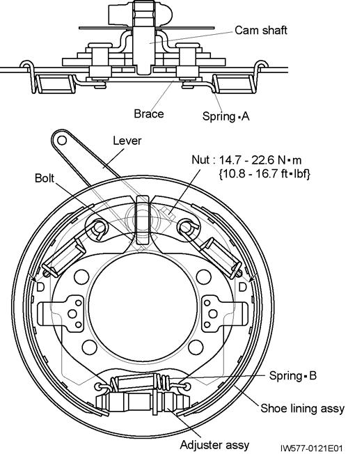
1. LEver is tilted right in this figure; it is tilted left on certain modelsbecause of the brake chamber position.
2. Apply grease to the sliding sections (*1 and *2) when assembling the brake.
Brake (Parking Brake)
2. Disassembly
2.1 Removing the brake shoes
1. Jack up the crane, and compress the spring chamber by air pressure to the end of its stroke.
2. Disconnect the spring chamber and lever, so that the brake drum can be turned. Then remove the brake drum.
3. Make marks on the parts of the shoe lining assy and adjuster assy to ensure that they are replaced in their original positions when reassembled.
4. Remove springsïA (2 springs), and remove the brace.
2.2 Removing the cam shaft
1. Make sure that the alignment marks are present at the connection between cam shaft and lever. Put the marks if they are unclear.
2. Remove bolt to remove lever from cam shaft.
3. Remove waved washer from cam shaft and remove the cam shaft from support plate assy.
NOTICE]
To remove the shoe lining assy, more the brake shoe outward until the anchor end of the shoe comes off the anchor pin.
5. Remove shoe lining assy and adjuster assy from support plate assy.
Brake (Parking Brake)
3. Check [NOTICE]
Before checking, remove worn lining powder, mud, and any other dirt form all parts. Also wipe away deposited oils (lubricants).
3.1 Checking shoe lining assy
1. Replace the lining if it is worn to a point where its surface is less than 0.8mm (0.031in) from the rivet head.
2. Replace the lining if the cam shaft contacting surface of the shoe wave is excessively worn.
3. Replace the lining if it is contaminated with oil or grease.
3.2
Checking adjuster assy
Repair or replace the adjuster assy if a damaged or crushed threads are evident.
3.3 Checking cam shaft
A damaged or excessively worn cam shaft should be replaced.
3.4 Checking springs
Replace springs if they are excessively worn or have gaps between coils when they are free.
3.5 Checking support plate assy
An excessively worn, deformed or cracked support plate assy should be replaced.
3.6 Checking brake drum
1. Check for wear and deformation.
2. Inside diameter of brake drum
Assembly standard: Φ 254 ~ 254.3 mm (10 ~ 10.01in)
Usable limit: Φ 256 mm(10.08in)
4. Reassembly [NOTICE]
When assembling, apply grease to the sliding parts (marked with *1 and *2 on page 1.)
1. Install adjuster assy on both shoe wave ends.
2. Move the brake shoes in such a way as to place the anchor ends of the brake shoes one upon the other, and install springïB in the holes of the shoe waves.
3. Install shoe lining assy on support plate assy.
4. Move the anchor ends of the brake shoes outward and install camshaft.
5. Fit wave washers on the ends of cam shaft, and install lever, while lining up alignment marks. Secure the lever by tightening nut.
6. Install brace on the anchor pins.
7. Fit one end of springïA in the hole of the shoe wave. While elongating the spring, hook the other end on the head of the anchor pin.
Brake (Parking Brake)
5. Adjustment
5.1 Adjusting the brake [NOTICE]
Perform the brake adjustments before the brake is connected to the spring chamber.
1. Jack up the crane, and rotate the brake drum and align the adjustment hole of the drum with the star wheel of adjuster assy.
2. Use a screwdriver inserted into the adjustment hole to expand the brake shoes until resistance is felt when the drum is rotated.
3. Under these conditions, back off the star wheel by 8 teeth. The clearance between the lining and brake drum is now adjusted to 0.23 mm(0.009in).
Proper clearance: 0.1 - 0.25 mm (0.004 - 0.01in)
5.2 Connecting the spring chamber
1. Keep the parking brake lever at the 0 point (center of lever play).
2. Compress the spring chamber to the end of its stroke (stroke end when extended by air pressure). At the stroke end, connect the chamber and brake lever.
3. Now check that there is no friction between the drum and lining, and lock in position with the nut.
U-1 Suspension System
1. General
Hydraulic Circuit for Suspension
Suspension System
1. Leaf springs are employed for both the front and rear axle suspensions.
2. The suspension lock function is either activated or released by the four spring lock cylinders installed between the carrier frame and front/rear axles. These four spring lock cylinders are hydraulically controlled by the solenoid valve (spring lock) and the solenoid valve (spring lock check release). These solenoid valves are switched according to the outputs from the multiplex data transmitter (lower).
3. There are two kinds of pressure controlling valves in the spring lock hydraulic circuit, namely a relief valve and a pressure reducing valve. The relief valve limits the highest pressure in the circuit, and the pressure reducing valve supplies the pilot pressure to the solenoid valve (spring lock) and the solenoid valve (spring lock check release).
Spring Lock Cylinder (Front)
U-2 Spring Lock Cylinder (Front)
[NOTICE]
There is a case that the appearance and so on differ from the parts for this machine. Although there is not so much difference in functions and disassembly procedures, make sure of the serial number of this machine and the part sales unit described in the parts catalog before starting disassembling operations.
1. Structure
*1: Face the notch or the lip toward the pressurized side. Thread size and tightening torque
Spring Lock Cylinder (Rear)
U-3 Spring Lock Cylinder (Rear)
[NOTICE]
There is a case that the appearance and so on differ from the parts for this machine. Although there is not so much difference in functions and disassembly procedures, make sure of the serial number of this machine and the part sales unit described in the parts catalog before starting disassembling operations.
*1: Face the notch or the lip toward the pressurized side.
Thread size and tightening torque
Pilot Check Valve (Spring Lock Cylinder)
U-4 Pilot Check Valve (Spring Lock Cylinder)
[NOTICE]
There is a case that the appearance and so on differ from the parts for this machine. Although there is not so much difference in functions and disassembly procedures, make sure of the serial number of this machine and the part sales unit described in the parts catalog before starting disassembling operations.
Solenoid Valve (Spring Lock Check Release)
U-5 Solenoid Valve (Spring Lock Check Release)
[NOTICE]
There is a case that the appearance and so on differ from the parts for this machine. Although there is not so much difference in functions and disassembly procedures, make sure of the serial number of this machine and the part sales unit described in the parts catalog before starting disassembling operations.
1. Structure
1.Solenoid valve (DC24V)
2.Body
3.Plug
4.O-ring
Thread size and tightening torque Tightening torque
Solenoid Valve (Spring Lock Check Release)
1.
