8 minute read
Winch System


The remote control valve is connected to the hydraulic pilot control valve at the two points having the same symbols such as "a2" and "b2". For a "1M1D"-specification crane without the auxiliary winch, seven portions "*2" are plugged.
1. The main winch is controlled by the hydraulic pilot method. The pilot pressure from the remote control valve controls the hydraulic pilot control valve.
2. The maximum pressure in the main winch hydraulic circuit is regulated by the relief valve (main winch, auxiliary winch).
3. The overload relief valve (down) regulates the maximum pressure in the hoist-down circuit for the main winch. This valve suppresses the surge pressure that may occur in a sudden hoist-down operation so as to assure a smooth hoist-down movement. In case of sudden stoppage of hoist-down movement, the relief valve integrated in the counterbalance valve operates to protect the hydraulic motor for the main winch.
4. Circuit for remote control pressure vent
In this hydraulic circuit, the hydraulic valve (pilot pressure) controls the pilot pressure to the remote control valve (main winch) and the hydraulic valve (winch brake release).
F-2 Winch [NOTICE]
There is a case that the appearance and so on differ from the parts for this machine. Although there is not so much difference in functions and disassembly procedures, make sure of the serial number of this machine and the part sales unit described in the parts catalog before starting disassembling operations.
1. Structure
Thread size and tightening torque
52. Plug
2. Reassembly [NOTICE]
Apply ThreeBond 1104 to the mating surfaces of the gear caseï1 and seat packingï19, and the mating surfaces of the case coverï2 and seat packingï19.
Apply ThreeBond 1104 to the mating surfaces of the gear caseï1 and coversï10,ï11,ï12,ï13, andï14.
Apply ThreeBond 1303 to the screw threads of the hexagon socket head boltï28. After tightening, mark with yellow paint.
When installing the spacerï9, bearingï24, drum gear Dï6, spacer ï8, and bearingï23 to the drum shaftï7, tighten the bearing nutï37 to apply axial force to the spacerï9.
At this time, install the 30 -tapered part of spacerï9 into the drum.
Hydraulic Motor (Winch)
F-3 Hydraulic Motor (Winch)
[NOTICE]
There is a case that the appearance and so on differ from the parts for this machine. Although there is not so much difference in functions and disassembly procedures, make sure of the serial number of this machine and the part sales unit described in the parts catalog before starting disassembling operations.
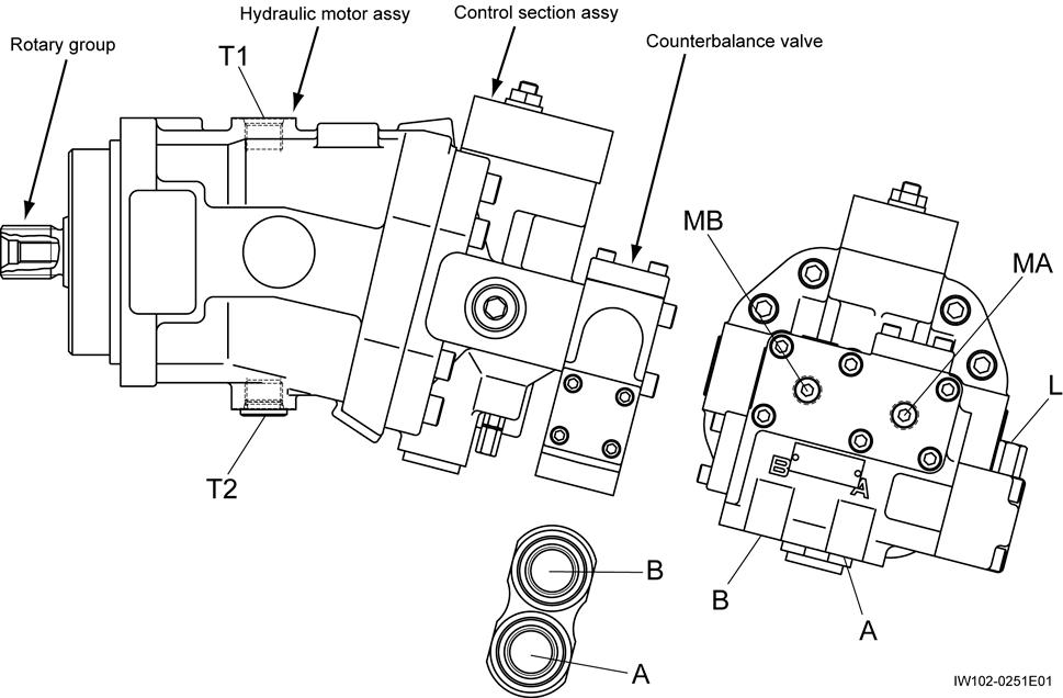
1. Structure
Hydraulic symbols
Thread size and tightening torque
Hydraulic Motor (Winch)
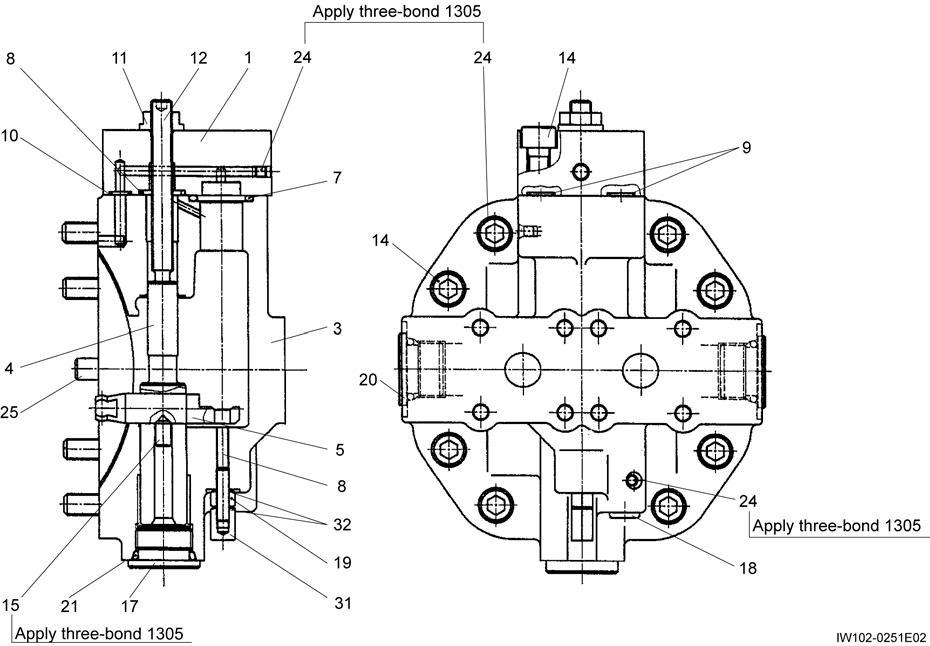
1.2 Control section assy
Hydraulic Motor (Winch)
Thread size and tightening torque
Hydraulic Motor (Winch)
2. Functions [NOTICE]
The construction shown below may differ from the parts of the actual equipment, however there are no major differences in function or disassembly procedure. Use the contents below for reference.
1. The direction of drive shaft rotation is determined by the inlet and outlet ports of the supplied oil.
Rotation direction (viewed from shaft side) Port A Port B
Left (hoist-up) Inlet Outlet
Right (hoist-down) Outlet Inlet
2. The drive shaft is supported in the housing by bearings A and B. 7 pistons are attached to the shaft end, and rotate together with the cylinder block. The cylinder block rotates and slides on a control plate that contains 2 oil channels. The control plate slides on the control section sliding surface. The sliding surface contains oil channels, which are connected to the inlet and outlet ports.
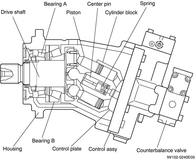
3. The position of the cylinder block is maintained by the center pin. When operating with no load, the cylinder block is pressed against the control plate by means of a spring. When the pressure increases, the hydraulic pressure results in the formation of the necessary lubricating oil film on the sliding surfaces. The resulting oil leakage is extremely small, and high volumetric efficiency is maintained at all times.
4. Hydraulic pressure moves the piston from the bottom dead center position to the top dead center position, turning the drive shaft. Hydraulic pressure then acts on the other pistons, turning the drive shaft, and moving this piston from top dead center position to bottom dead center. This pushes the oil inside the cylinder block out to the outlet port.
5. The axis center of the cylinder block is inclined at an angle to the axis center of the drive shaft. This generates the piston stroke, and determines the discharge rate for 1 rotation of the drive shaft.
Hydraulic Motor (Winch)
3. Disassembly
[NOTICE]
These are precision parts. Be sure to perform disassembly and assembly in a clean environment, and use sufficient care in handling the parts. Handle parts carefully to avoid dropping them or striking them on other objects. While working, using excessive force to strike or pry parts can cause burrs or damage that will prevent assembly or decrease performance. Use caution. For the hydraulic motor, after plugging all ports beforehand and cleaning with kerosene, make alignment marks on all mating surfaces. When replacing the rotary group and control section assy, replace the entire assy.
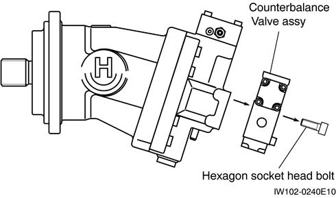
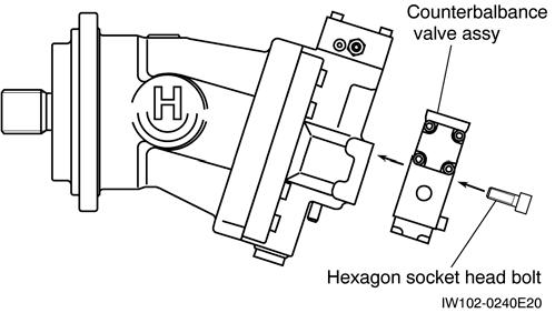
3.1 Removing the counterbalance valve
1. Remove the hexagon socket head bolt.
2. Remove the counterbalance valve assy.
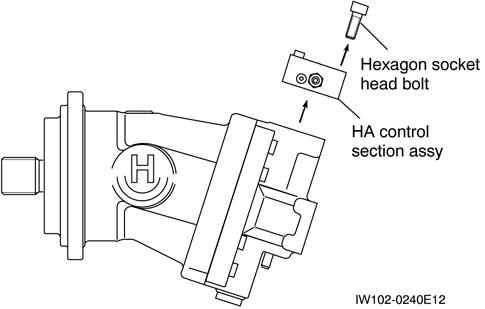
3.3 Removing the control section assy
1. Remove the hexagon socket head bolt.
2. Remove the HA control section assy.
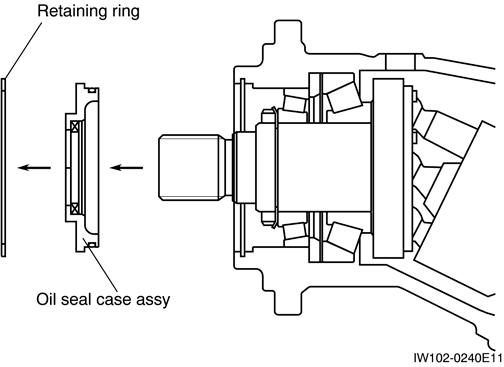
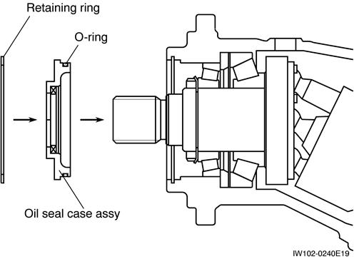
3.2 Removing the oil seal case
1. Remove the retaining ring, then remove the oil seal case assy.
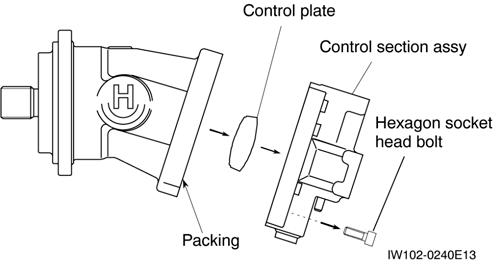
3. Remove the hexagon socket head bolt.
[NOTICE]
Be careful not to allow the cylinder block to fall.
4. Remove the control section assy, control plate, and packing.
5. To prevent the cylinder block from falling, fix it in place with a rubber disc and hexagon socket head bolt (M8).
Rubber disk
Hexagon socket head bolt
Cylinder block
Hydraulic Motor (Winch)
4. Reassembly [NOTICE]
Be sure to thoroughly clean all parts. Check carefully that there are no dropped parts or parts with scratches on them. Replace the O-ring and packing with new parts. To prevent them from falling off, apply grease before installing.
When assembling, be careful that no foreign objects become included with the parts.
After assembling, leave for 12 hours to allow the adhesive to harden.
4.1 Installing the control section assy
1. As shown in the figure, use square lumber to stand the housing upright.
2. Apply sealant (ThreeBond 1215 or equivalent) to the mating surfaces of the housing and control section assy.
[NOTICE]
When installing the control plate, be careful to install it facing in the correct direction (as shown in the figure below).
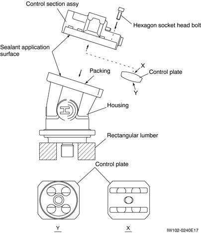
3. Apply grease to the control plate, and install the control plate onto the control section assy.
4. Remove the rubber disc and hexagon socket head bolt that were used to prevent the cylinder block from falling.
5. Install the packing and control section assy. Tighten with the hexagon socket head bolt. (Be careful not to allow the control plate to fall.)
4.2 Installing the oil seal case
1. Install the O-ring onto the oil seal case assy.
2. Install the oil seal case assy into the housing. Install the retaining ring.
4.3 Installing the counterbalance valve
1. Install the counterbalance valve assembly. Tighten with the hexagon socket head bolt.
Counterbalance Motor (Winch)
F-4 Counterbalance Valve (Winch)
[NOTICE]
There is a case that the appearance and so on differ from the parts for this machine. Although there is not so much difference in functions and disassembly procedures, make sure of the serial number of this machine and the part sales unit described in the parts catalog before starting disassembling operations.
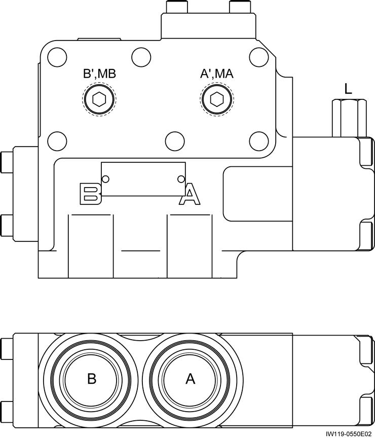
1. Structure
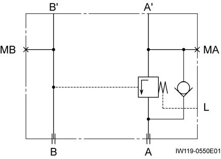
Hydraulic symbols
Counterbalance Motor (Winch)

Counterbalance Motor (Winch)
Thread size and tightening torque
*1:Apply LOCTITE 242
Hydraulic Valve (Winch Brake Release)
F-5 Hydraulic Valve (Winch Brake Release)
[NOTICE]
There is a case that the appearance and so on differ from the parts for this machine. Although there is not so much difference in functions and disassembly procedures, make sure of the serial number of this machine and the part sales unit described in the parts catalog before starting disassembling operations.
Hydraulic symbols
Winch Brake Band
F-6 Winch Brake Band [NOTICE]
There is a case that the appearance and so on differ from the parts for this machine. Although there is not so much difference in functions and disassembly procedures, make sure of the serial number of this machine and the part sales unit described in the parts catalog before starting disassembling operations.
1. Structure
23.
34.
35.
37. Bolt
27.
29.
30.
31.
38.
39.
40.
41.
42.
43.
Winch Brake Band
Thread size and tightening torque
2. Principle of operation
2.1 Automatic braking when the control lever is in the neutral position
[NOTICE]
Support A, the rod, and pin A (indicated by shading) are non-movable parts that are fixed to support B.
2.2 Automatic braking cancellation during hoisting or free-fall operation
1. When the control lever is in the neutral position, the oil in the automatic brake cylinder is directed to the tank.
2. The automatic brake cylinder is pressed by spring A, and moves to the right, pressing upon support C.
3. Support C moves the brake band, generating braking force.
1. During hoisting or ìfree-fallî operation, brake release pressure is directed from the accumulator to the automatic brake cylinder.
2. The brake cylinder moves to the left, and compresses spring A. The spring force that was acting on support C disappears, and the brake band is pulled back by spring B, releasing the brake.
Winch Brake Band
2.3 Braking by foot brake during free-fall operation
Braking
3. Disassembly and reassembly [NOTICE]
Compress the cylinder spring before performing disassembly / reassembly work. To compress the spring, screw a hex. socket head bolt (fully threaded M8× 45 bolt) into section. Do not allow brake oil or other vegetable oils to contact the cylinder.
Accumulator pressure Brake pressure
Support C (Master cylinder)
IW528-0110E04
1. The automatic brake cylinder moves to the left, as described in the previous item.
2. When the winch brake pedal is depressed, brake pressure is directed from the master cylinder to the brake cylinder on the right side.
3. Force is applied to the right-side cylinder, acting toward the right. The cylinder moves support C and the brake band, generating braking force.
3.1 Reassembly of cylinder sections
1. Apply a thin coat of lithium base grease (Daphhe Colonex Grease EP1 or equivalent) to the inside surfaces of cylinders (G1 section) before reassembly. (Hereinafter, ìgreaseî refers to the same grease as the above-mentioned one.)
2. Apply grease generously to the outer surfaces of pistons (2 places) before reassembly.
3. Apply grease generously to the sliding sections (G2, G3, and G4 sections).
4. Adjustment
4.1 Adjustment of shim
1. Screw a hex. socket head bolt (fully threaded M8 45 bolt) into section A until dimension X becomes zero.
2. Push supportïA to the right until dimension C becomes zero.
3. Measure dimension B. Determine the shim stock thickness using the following formula and select and install shim(s) corresponding to the obtained thickness. Shim thickness = (B - 10) ± 0.3 mm [(B-0.4)±0.01in]
4. Remove the hex. socket head bolt.
4.2 Adjustment of stroke
[NOTICE]
Adjust the stroke after adjusting by shims.
1. Adjust the adjusting bolt so that distance L is 18 mm. (0.7in)
2. Supply hydraulic pressure to the cylinder to move it until dimension X becomes zero. Make sure that the hydraulic pressure is 20.6 MPa (2987psi) or less.
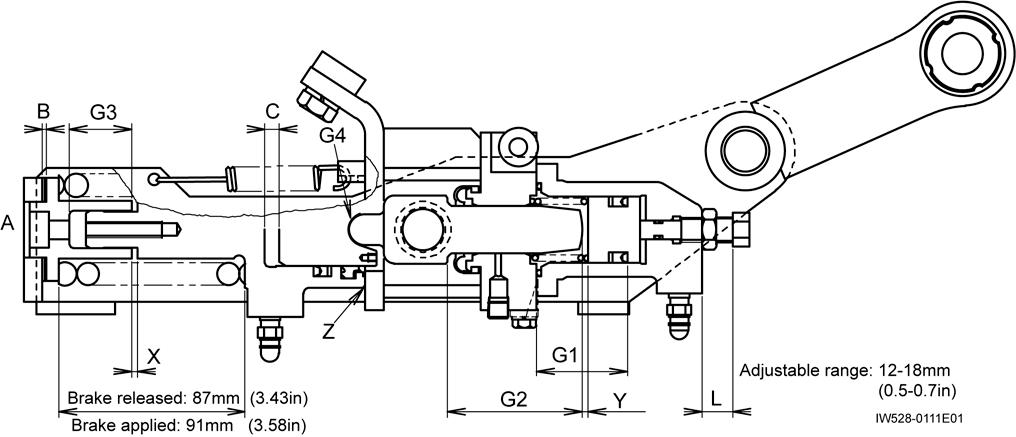
[NOTICE]
Be careful not to screw the bolt in too far. A gap will be produced at portion Z.
3. Screw in the adjusting bolt until dimension Y becomes zero and lock it with lock nut.
4. Measure distance L. Check that it is within the range 15 ± 2 mm. (0.6±0.08in)

