12 minute read
Hydraulic Circuit for Outrigger


1. The outrigger controls use the solenoid control valve to select between extension or retraction for each cylinder. The solenoid valve selects between operation of the extension cylinder and the jack cylinder.
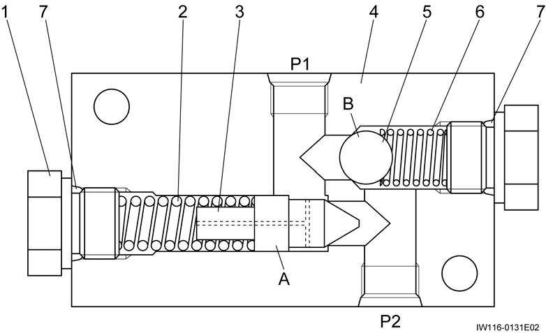
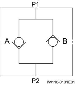
2. During outrigger extension, the pressure oil from the pump passes through the solenoid control valve and solenoid valve to enter the cylinders.
3. At this time, back pressure is generated in the return oil by the pilot check valve. The return oil then passes through the solenoid control valve and returns to the tank.
4. During outrigger retraction, the pressure oil passes through the solenoid control valve and pilot check valve, and operates on the retraction side of the extension and jack cylinders. Only the circuit of the cylinder selected by the solenoid valve retracts.
5. The maximum puressure in the outrigger hydraulic circuit is regulated by the relief valve.
Outrigger System
1. The solenoid valve (extending/retracting) and the four solenoid valves (slide/jack) are switched according to the outputs from the multiplex data transmitter (lower). The outputs to the four solenoid valves (slide/jack) are transmitted via the relay RF3.
Jack Cylinder
C-2 Jack Cylinder [NOTICE]
There is a case that the appearance and so on differ from the parts for this machine. Although there is not so much difference in functions and disassembly procedures, make sure of the serial number of this machine and the part sales unit described in the parts catalog before starting disassembling operations.
1. Structure
Pilot Check Valve (Jack Cylinder Retracting Prevention)
C-3 Pilot check Valve (Jack Cylinder Retracting Prevention)
[NOTICE]
There is a case that the appearance and so on differ from the parts for this machine. Although there is not so much difference in functions and disassembly procedures, make sure of the serial number of this machine and the part sales unit described in the parts catalog before starting disassembling operations.
Structure
Extension Cylinder
C-4 Extension Cylinder [NOTICE]
There is a case that the appearance and so on differ from the parts for this machine. Although there is not so much difference in functions and disassembly procedures, make sure of the serial number of this machine and the part sales unit described in the parts catalog before starting disassembling operations.
1. Structure
Solenoid Valve (Slide/Jack) (UCHIDA)
C-5 Solenoid Valve (Slide/Jack) (UCHIDA)
[NOTICE]
There is a case that the appearance and so on differ from the parts for this machine. Although there is not so much difference in functions and disassembly procedures, make sure of the serial number of this machine and the part sales unit described in the parts catalog before starting disassembling operations.
Solenoid Valve (Slide/Jack) (TOKIMEC)
C-6 Solenoid Valve (Slide/Jack) (TOKIMEC)
[NOTICE]
There is a case that the appearance and so on differ from the parts for this machine. Although there is not so much difference in functions and disassembly procedures, make sure of the serial number of this machine and the part sales unit described in the parts catalog before starting disassembling operations.
Note: Install the centering washer (10) with its slit directed toward the body
Thread size and tightening torque
Solenoid Valve (Slide/Jack) (NACHI)
C-7 Solenoid Valve (Slide/Jack) (NACHI)
[NOTICE]
There is a case that the appearance and so on differ from the parts for this machine. Although there is not so much difference in functions and disassembly procedures, make sure of the serial number of this machine and the part sales unit described in the parts catalog before starting disassembling operations.
Thread size and tightening torque
Check Valve (Outrigger Extending Prevention)
C-8 Check Valve (Outrigger Extending Prevention)
[NOTICE]
There is a case that the appearance and so on differ from the parts for this machine. Although there is not so much difference in functions and disassembly procedures, make sure of the serial number of this machine and the part sales unit described in the parts catalog before starting disassembling operations.
1. Structure
Thread size and tightening torque
D-1 Swing System
1. General Hydraulic Circuit for Swing
Swing System
Swing System
[NOTICE]
The remote control valve and the solenoid control relief valve are connected to the hydraulic pilot control valve at the two points having the same symbols such as “a6” and “b6”.
1. The swing operation is controlled by the hydraulic pilot method. The pilot pressure from the remote control valve controls the hydraulic pilot conrtol valve.
2. The maximum pressure in the swing circuit is regulated by the relief valve. In cace of sudden stoppage of swing movement, the overload relief valve (high pressure) in the circuit with unusually high pressure operates to protect the hydraulic motor for swing operation.
3. Circuit for swing automatic stop
The right swing proportional control valve and the left swing proportional control valve serve to automatically stop the swing movement. These valves control the swing operation according to the output from the AML.
4. Circuit for swing brake release
In this hydraulic circuit, the solenoid valve (swing brake release) controls the pilot pressure to the brake release port of the hydraulic motor for swing operation.
5. Circuit for remote control pressure vent
In this hydraulic circuit, the solenoid valve (remote control pressure vent) controls the pilot pressure to the remote control valve.
Swing Assembly
D-2 Swing Assembly
[NOTICE]
There is a case that the appearance and so on differ from the parts for this machine. Although there is not so much difference in functions and disassembly procedures, make sure of the serial number of this machine and the part sales unit described in the parts catalog before starting disassembling operations.
1. Structure
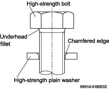
1.Bolt
2.Plain washer
[NOTICE]
Apply torque control agent to the threaded sections of the bolts. Place the high-strength plain washer orienting its chamfer to the underhead fillet as shown below.
Thread

2. Swing bearing mounting bolt
2.1 Bearing lnner ring bolts
Swing Assembly
1.Bolt (L=90mm) 2.Pain
[NOTICE]
Install the bearing inner ring with the “S” mark facing the rear of the carrier.
Apply torque control agent to the threaded sections of the bolts. (1 and 3)
Place the high-strength plain washer orienting its chamfer to the underhead fillet as shown below.
Thread size and tightening torque
2.2 Bearing outer ring bolts
Swing Assembly
1.Bolt (L=110mm)
2.Plain washer (28points)
3.Bolt (L=100mm)
4.Pin
[NOTICE]
Install the bearing inner ring with the “S” mark facing the rear of the carrier.
Place the high-strength plain washer orienting its chamfer to the underhead fillet as shown below.
Thread size and tightening torque
Tightening torque Sign / portThread size N-m
1 (9 points)
3 points)
Hydraulic Motor (Swing)
D-3 Hydraulic Motor (Swing)
[NOTICE]
There is a case that the appearance and so on differ from the parts for this machine. Although there is not so much difference in functions and disassembly procedures, make sure of the serial number of this machine and the part sales unit described in the parts catalog before starting disassembling operations.
1. Structure
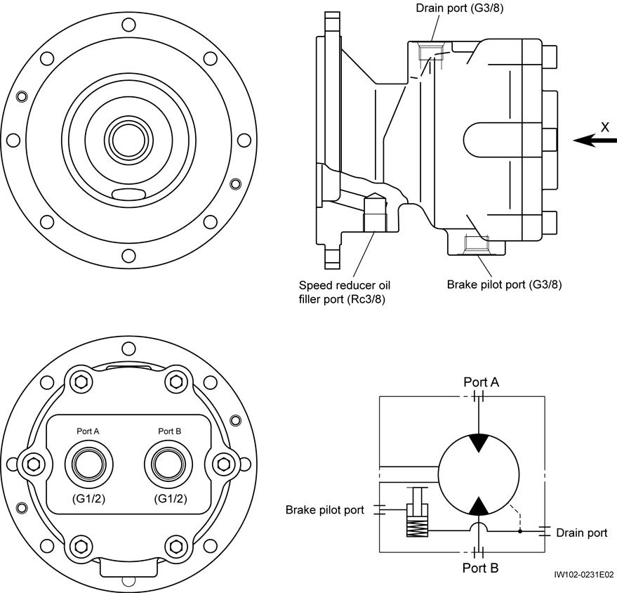
Hydraulic Motor (Swing)
Retaining ring
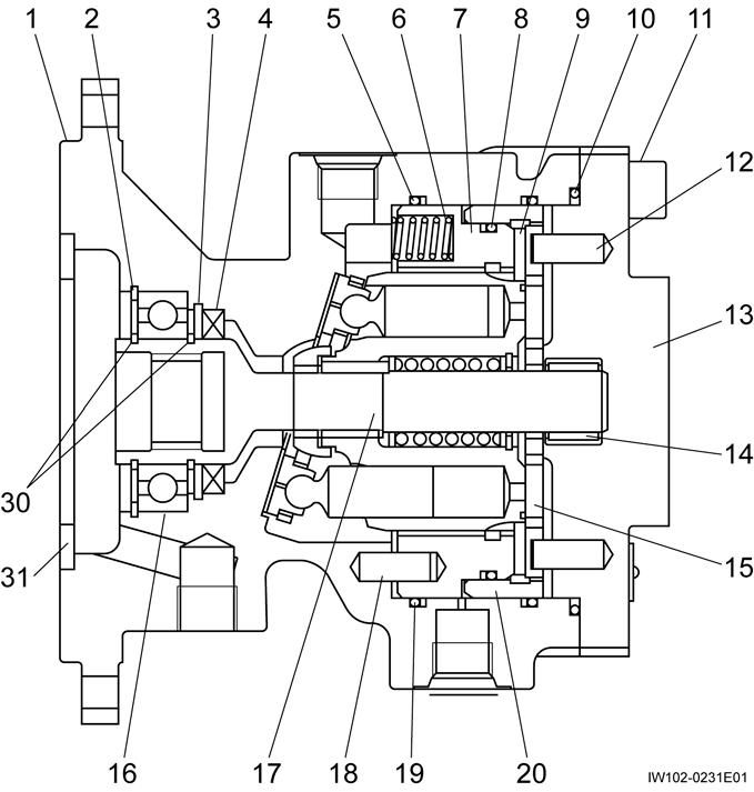
2. Functions
Hydraulic Motor (Swing)
1. The hydraulic motor is rotated by supplying a high pressure fluid from port A and discharging a low pressure fluid from port B, or vice versa.
2. When a high pressure fluid is supplied from port B instead of port A, the only difference that will result from this change is the rotating direction of the motor. The following explanations assume the case in which the hydraulic fluid flows from port A to port B.
3. The high pressure fluid (pressure PA) supplied from port A flows into piston chamber A in the cylinder block. As the piston is moved by the fluid pressure, the internal state of the motor continuously changes from the one represented by the upper half of figure to the one represented by the lower half of the figure, allowing the fluid to move toward port B.
4. The piston then moves from the position represented by the lower half of the figure to the one represented by the upper half of the figure, while discharging low pressure fluid through port B.
5. The piston presses the piston shoe with a force proportional to the pressure PA, and the rectangular component F1 of its reactionary force F causes the motor to generate a torque.
Hydraulic Motor (Swing)
6. There are a total of 9 pistons, the four or five of which are involved in performing the function described in 5. above at the port A side.
7. Figure shows a state where the brake is released. The spring in the brake piston always presses the brake piston to the right, keeping the piston pressed against the brake disc.
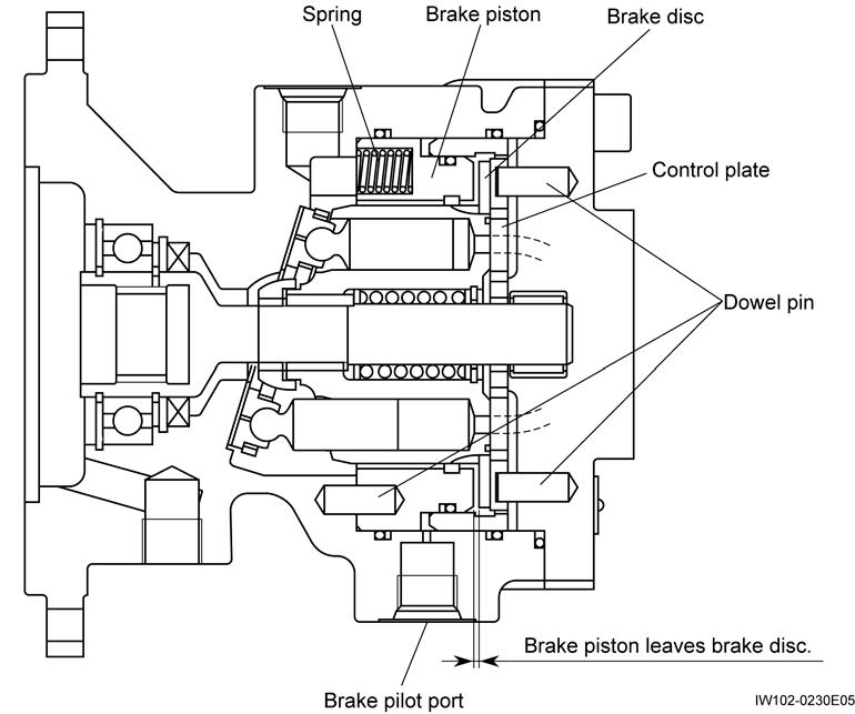
8. The brake disc is splined to the cylinder block. The braking action occurs when the brake disc is pressed against the control plate (fixed to the cover by dowel pins) by the force of the brake piston.
9. Figure shows a state where the brake is released by the hydraulic pressure applied through the brake pilot port. The pilot hydraulic pressure moves the brake piston back to the left, freeing the brake disc to release the brake.
Hydraulic Motor (Swing)
3. Disassembly [NOTICE]
Avoid using a copper hammer. Copper particles could enter the motor. Be extremely careful when handling the inner parts of the motor. Most of them are quite sensitive to damage such as dents and scratches. Place the removed parts in good order for ready reassembly. Try to maintain their original assembly relationships.
The sealing parts, once removed, must not be reused. Always install new sealing parts after coating with grease.
3.1 Jig for disassembling
Unit of dimension is “mm” (1 mm=0.039 in)
1. For removal of brake piston and ring
Round or square of 15 to 25 mm diameter or width
3.2 Disassembly
1. Put a mark across housing•1 and cover•13.
IW102-023010
2. Loosen hexagon socket head bolts•11 that secure cover•13.
IW102-0230E06
2. For installation of oil seal 10 20
Produced from a one-piece material
IW102-023011
Nut
Produced by using a bolt (M12 or equivalent size) 100 150 7
IW102-0230E07
3. For removal of oil seal
3. Remove cover•13.
IW102-023012
Hydraulic Motor (Swing)
4. Insert a blade screwdriver into the slot formed in the cover and lever up control plate•15 to remove.
7. Insert screwdriver blades into the internal circumferential groove of the brake piston•7. Lever the piston up using the drive shaft end as a fulcrum.
8. Place the jig on the drive shaft end to have a raised fulcrum and lever the piston up to remove.
9. Insert screwdriver blades into the internal circumferential groove of the brake piston ring•20. Remove the ring using the same procedure as for the brake piston•7.
IW102-023013
5. Remove brake disc•9.
IW102-023016
[NOTICE]
IW102-023014
6. Remove cylinder block•26. Piston assy•24 and dowel pins•25 (3 pieces) will remain in the motor.
There are 3 of the dowel pin•25. Be careful with them as they are easy to lose.
10. Remove the piston assy•24, retainer•21, guide•22, and dowel pins•25 (3 pieces).
IW102-023017
IW102-023015
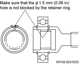
11. Remove retaining ring•2.
Hydraulic Motor (Swing)
12. Lightly tap the rear end of the drive shaft with a plastic hammer, and remove the shaft•17.
15. Remove the retaining ring•3 so that the oil seal•4 can be removed.
13. Remove retaining ring•30 (at the shaft end).
16. Hold a screwdriver with bent blade against oil seal•4 and tap it with a hammer.
[NOTICE]
Use the bearing removing jig.
14. Tap the drive shaft end with a plastic hammer to remove the bearing.
17. Remove plate•23.
Hydraulic Motor (Swing)
4. Reassembly
4.1 Installation of oil seal
1. Fit the oil seal•4 on the oil seal installation jig. Fill the space between lips of the oil seal with grease.
Inject grease
2. Fit retaining ring•30.
Oil seal Installing Direction
IW102-0230E25
2. Tap the jig with a hammer to force the oil seal into housing•1.
3. Install the shaft in the housing.
4. Fit retaining ring•2 in position.
5. Apply grease to both sides of plate•23 and fit the plate in place in the housing.
IW102-023047
3. Fit retaining ring•3 in position.
4.2 Reassembly of shaft section
1. Tap bearing•16 with a plastic hammer to install it on shaft•17.
Plate Installing Direction Housing side (reverse side)
Piston assembly side (front side)
IW102-0230E29
Hydraulic Motor (Swing)
6. Apply grease to O-ring•5 and fit the O-ring in the brake portion of housing•1.
[NOTICE]
Exercise care to prevent the three pins from falling off.
3. Install the combination of guide•22, retainer•21 and piston assemblies•24 in cylinder block•26. Before installation, apply grease to the spherical surface of the guide and the cylindrical surfaces of the piston assemblies.
4.3 Reassembly of rotary assembly
[NOTICE]
Be careful to assemble in the correct direction.
1. Install piston assemblies•24 in retainer•21
Chamfered Spherical
4. Install the rotary assembly in the housing.
[NOTICE]
Install the pins in the locations where the spline teeth are omitted (3 places).
2. Apply grease to pins•25 (3 pieces) and install the pins in cylinder block•26.
5. Check that the rotary assembly is in the correct position.
Location where there are no spline teeth.
Hydraulic Motor (Swing)
4.4 Installation of brake piston
1. Put a mark at the position that is in line with dowel pin•18.
[NOTICE]
Exercise care to prevent the springs from falling off.
5. Align the alignment marks on the brake piston and housing, and insert the piston.
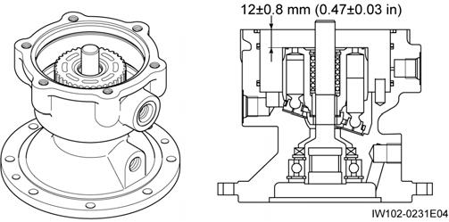
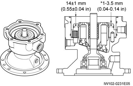
2. Put a mark on brake piston•7 at the position that is in line with dowel pin.
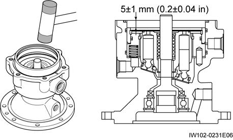
6. Make sure that the brake piston is in the correct position. Check the dimension marked * at least.
3. Apply grease to the entire circumference of the O-ring•8, then install the O-ring onto the brake piston.
4. Apply grease to springs•6 and install the springs in the brake piston.
Hydraulic Motor (Swing)
4.5 Installation of brake cover
1. Install the brake disc so that its portions with omitted internal teeth with the notches (3 places) on the outer circumference of the cylinder block.
4. Install O-ring•10 on the housing at the surface that joins with the cover.
5. Align the alignment marks that were made when the cover was disassembled, and attach the cover onto the housing.
2. Install brake ring•20 by tapping it with a plastic hammer. ammer.
6. Tighten the hexagon socket head bolts•11 (M10×30) diagonally and evenly.
Tightening torque: 48.1 ~ 61.8 N•m (35.5 ~ 45.6 ft•lbf)
5.
Test
[NOTICE]
Completely fill the housing with hydraulic oil by venting air, before starting.
[NOTICE]
The position and direction are determined by two dowel pins.
3. Apply grease to both sides of the control plate•15, then attach it to the cover•13.
5.1 Operation tests
1. Start the hydraulic motor and let it run at a low speed under no load for 10 to 15 minutes. Make sure that there are no abnormal sounds, vibration, etc.
2. If there are no abnormalities, apply load and proceed to high-speed operation. In the same way, check that there is no abnormal noise or vibration.
Swing Speed Reducer
D-4 Swing Speed Reducer [NOTICE]
There is a case that the appearance and so on differ from the parts for this machine. Although there is not so much difference in functions and disassembly procedures, make sure of the serial number of this machine and the part sales unit described in the parts catalog before starting disassembling operations.
1. Structure
1. This reducer is two-stage planetary-gear speed reducing mechanism.
2. The rotation power of the hydraulic motor is transmitted in the following order.
Motor output shaft Sun gear(28) planetary gear(25) carrier-A(5) Sun gear(14)
Planetary gear(8) carrier-B(21) reducer output shaft(16)
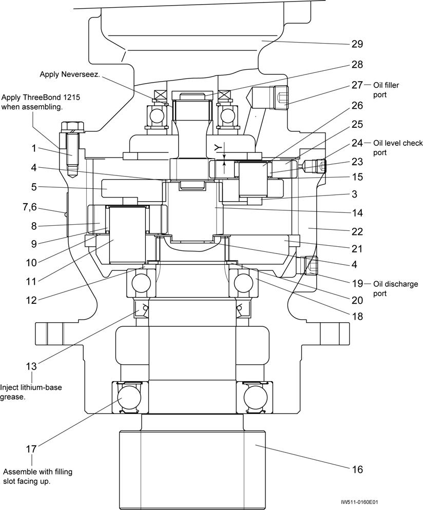
1.Bolt
Swing Speed Reducer
9.Needle bearing
10.Plate
11.king pin (B)
12.Spacer
17.Ball bearing
18.Ball bearing
19.Hexagon socket plug
20.Snap ring
25.Planetary gear
26.King pin (A)
27. Hexagon socket plug
28.Sun gear
5.Carrier (A)
6.Name plate
7.Rivet
8.Planetary gear
13.Oil seal
14.Sun gear
15.Plate
16.Output shaft (super gear)
21.Carrier (B)
22.Casing
23.Needle bearing
24.Hexagon socket plug
Thread size and tightening torque Tightening
2. Removing of hydraulic motor
[NOTICE]
After fixing the swing frame, remove the hydraulic motor and the reducer to prevent the swing frame from self-rotating.
1. Before disassembly, mark to each mating surface
2. Drain oil from the hydraulic motor and the reducer.
3. After removing bolts(1) (eight places) securing the hydraulic motor, remove the motor by using pulling-out screw (2-M8) on the motor flange.
29.Hydraulic motor assy
3. Disassembly of reducer
[NOTICE]
Disassembly and assembly should be always performed in a clean place caring dust and so on. Careful work is necessary. Do not beat and lever to prevent burrs and breakages that cause impossible assembly and performance deteriorations.
1. Take out parts from sun gear(28) to carrier-B(21).
[NOTICE]
King pins(11), (26) are fitted by shrinkage fitting, space(3) is fitted by caulking.
2. Remove snap ring(20), and remove output shaft(16) from casing (22) by using a press.
Swing Speed Reducer
4. Assembly of reducer
1. Press-fit ball bearing(17) on output shaft(16).
2. Press-fit oil seal(13) into casing(22).
[NOTICE] lithium type grease on the inner of oil seal(13).
3. Install output shaft(16) in casing(22).
4. Press-fit ball bearing(18) into output shaft(16), place in spacer(12), and fix it with snap ring(20).
5. Hereafter, assemble carrier B(21) to sun gear(28) in reverse order of "Disassemly of reducer."
[NOTICE]
Confirm sun gear(28) turns lightly by your hand. Secure clearance Y=0.15 to 2.32 mm (0.006 to 0.09 in) shown in figure of previous page when mounting the hydraulic motor.
5. Installation of hydraulic motor
1. Tighten hydraulic motor by bolt(1).
[NOTICE]
Apply THREE BOND 1215 on the mating surface between the hydraulic motor casing and the swing reducer.
2. Supply gear oil into the reducer via plug(27). (about 0.5L (30.5 in3))

