5 minute read
Hydraulic Power Generating System


1. The hydraulic oil provided from the pumps is controlled (onloaded/unloaded) by the solenoid valve. This solenoid valve for automatic stop is switched by the AML output to control the vent ports of the relief valve (elevating, telescoping) and the relief valve (main winch, auxiliary winch). When the PTO switch is turned on, the solenoid valve for automatic stop is shifted from the middle position to the AML vent position, making the condition of this circuit onloaded.
2. The pressurized oil delivered through the P1 port of the rotary joint is supplied to the circuits for the main winch and the auxiliary winch.
Circuits for swing, elevating, telescoping, main and auxiliary winches. Circuit for pilot pressure, air conditioner
The pressurized oil delivered through the P2 port of the rotary joint is provided to the circuits for elevating and telescoping. This oil, however, is supplied to the circuits for the main winch and the auxiliary winch while neither elevating nor telescoping operation is done. The pressurized oil delivered through the P6 of the rotary joint is provided to the circuit for swing.
1. The pressurized oil delivered through the P3 port of the rotary joint is supplied to these circuits. Pressurized oil reduced by the hydraulic valve(pilot pressure) is supplied to the circuit for the pilot pressure.
2. The pilot pressure is supplied to the swing brake release circuit, main winch brake release circuit, auxiliary winch brake release circuit, and pilot circuits for crane operations.
3. The pressurized oil delivered through the hydraulic valve(pilot pressure) is supplied to the circuit for the air conditioner.
Hydraulic Pump (Double Variable Displacement Pump)
B-2 Hydraulic Pump (Double Variable Displacement Pump)
[NOTICE]
There is a case that the appearance and so on differ from the parts for this machine. Although there is not so much difference in functions and disassembly procedures, make sure of the serial number of this machine and the part sales unit described in the parts catalog before starting disassembling operations.
1. Structure
Hydraulic symbols
This pump is a variable displacement piston pump.
The angle of the swash plate is controlled by the regulator.
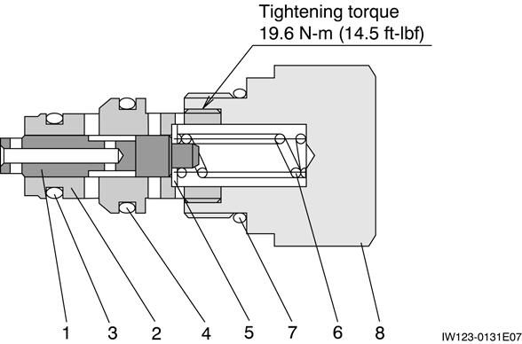
Thread size and tightening torque
Hydraulic Pump (Double Variable Displacement Pump)
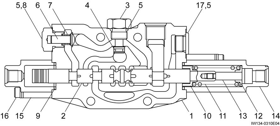
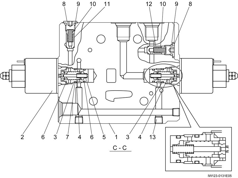
1.3 Control section (LV, front)
Hydraulic Pump (Double Variable Displacement Pump)
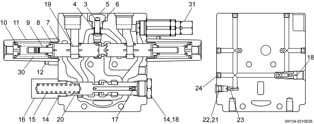
1.4 Control section (LV, rear)
2. Air bleeding procedure
Refer to ìAir Bleeding Procedureî in chapter Y.
B-3
Hydraulic Pump (Double Gear Pump)
B-3 Hydraulic Pump (Double Gear Pump)
[NOTICE]
There is a case that the appearance and so on differ from the parts for this machine. Although there is not so much difference in functions and disassembly procedures, make sure of the serial number of this machine and the part sales unit described in the parts catalog before starting disassembling operations.
2.
Hydraulic Pump (Gear Pump, Emergency Steering)(Option)
B-4 Hydraulic Pump (Gear Pump, Emergency Steering) (Option)
[NOTICE]
There is a case that the appearance and so on differ from the parts for this machine. Although there is not so much difference in functions and disassembly procedures, make sure of the serial number of this machine and the part sales unit described in the parts catalog before starting disassembling operations.
Hydraulic Valve (Emergency Steering) (Option)
B-5 Hydraulic Valve (Emergency Steering) (Option)
[NOTICE]
There is a case that the appearance and so on differ from the parts for this machine. Although there is not so much difference in functions and disassembly procedures, make sure of the serial number of this machine and the part sales unit described in the parts catalog before starting disassembling operations.
The arrow in Figure shows the flow of the oil at the emergency pump operation.
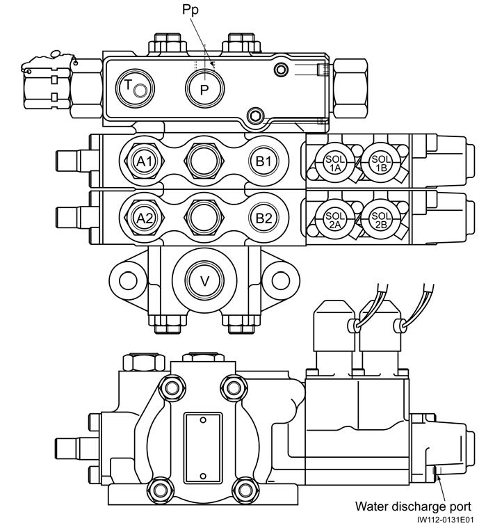
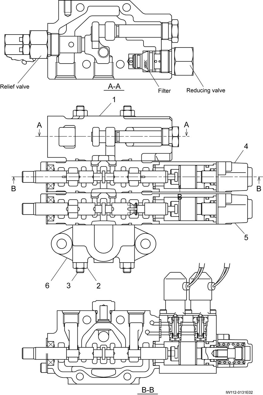
Solenoid Control Valve (Outrigger, Suspension)
B-6 Solenoid Control Valve (Outrigger, Suspension)
[NOTICE]
There is a case that the appearance and so on differ from the parts for this machine. Although there is not so much difference in functions and disassembly procedures, make sure of the serial number of this machine and the part sales unit described in the parts catalog before starting disassembling operations.
1. Structure
Hydraulic symbols
Solenoid Control Valve (Outrigger, Suspension)
Solenoid Control Valve (Outrigger, Suspension)
1.7 Reducing valve
Thread size and tightening torque
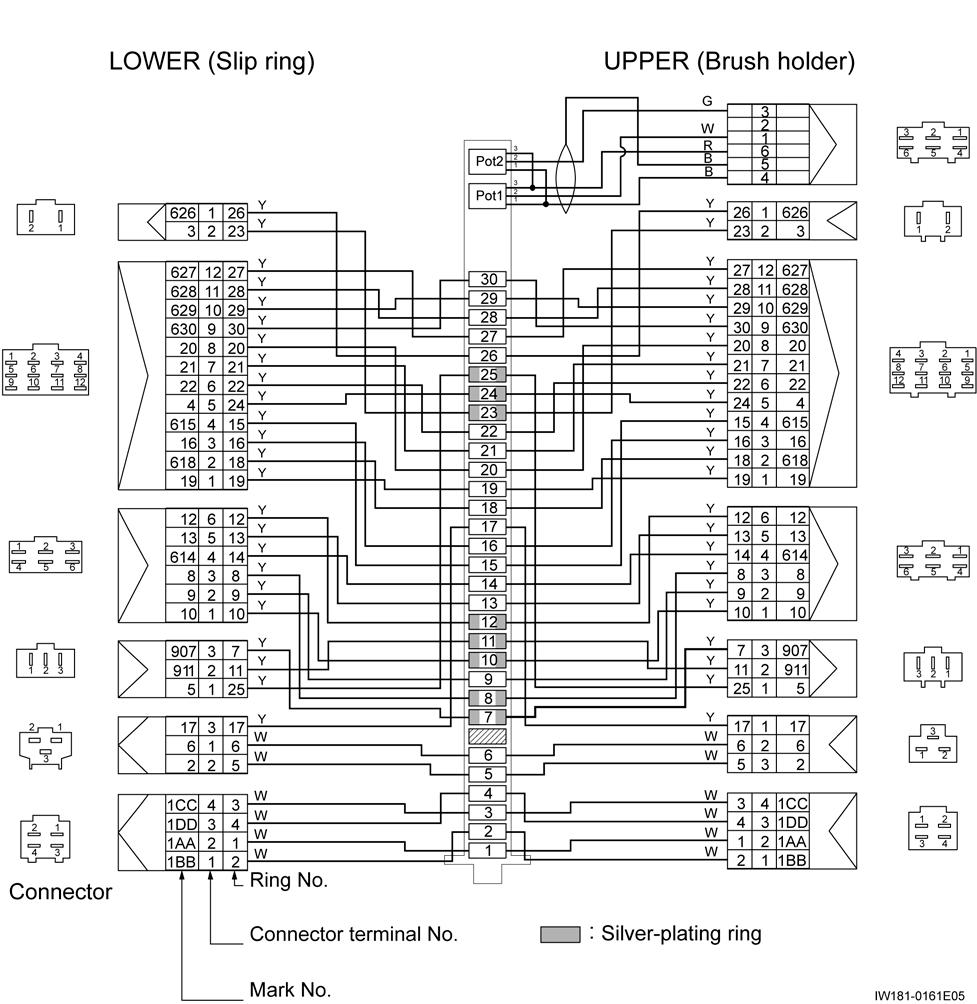
Rotary Joint
B-7 Rotary Joint [NOTICE]
There is a case that the appearance and so on differ from the parts for this machine. Although there is not so much difference in functions and disassembly procedures, make sure of the serial number of this machine and the part sales unit described in the parts catalog before starting disassembling operations.
1. Structure
1.1 General view
Rotary Joint
Thread size and tightening torque
Rotary Joint
Thread size and tightening torque
Rotary Joint
*1 : Apply Loctite 496 (Strong quick-bonding adhesive) to the screw threads.
2.1 Adjustment of potentiometer resistance [NOTICE]
The adjustment procedure is for the slip-ring assy single unit.
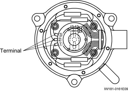
After soldering wires with terminals on the potentiometer [20], coat the terminals with an epoxy adhesive (3M DP-420 or equivalent). (to insulate terminals from each other)
1. Secure the potentiometer [20] to the support [14] with the machine screws [30] (3 places). Apply Loctite-496 (strong instanteneous adhesive) to the screw head of the machine screws [30].
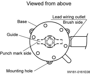
2. Orient the punch mark of the guide [18] to the direction shown in the figure below, and position the guide [18].
3. Attach the lever [23] to the potentiometer [20] temporarily.
4. Install the potentiometer-assy in the base [15]. At this time, orient the hole of the guide [25] to a direction which facilitates to install.
5. By using a flat-blade screwdriver, turn the top of the potentiometer to adjust the resistance between the upper terminals 1 and 2 (CPU1 side) so that the minimum resistance becomes between 1-ohm and 15-ohm.
[NOTICE]
Check that the clearance between the machine screws [30] and lever [23] is 0.5 mm (0.02 in).
6. Remove the previously installed potentiometer-assy from the base. Then fix the lever [23] securely which has been attached temporarily at the step 3.
7. Install the potentiometer-assy in the base [15] following the same procedure of step 4.
8. Orient the guide [18] following the same procedure of step 2. Then measure the potentiometer's resistance again, and make sure that it is 15 ohms or less.
9. Rotate the guide right and left and check that resistance varies within 3 ohms.
B-8
B-8
Hydraulic Pilot Control Valve (Swing, Elevating, Telescoping, Winch)
B-8 Hydraulic Pilot Control Valve (Swing, Elevating, Telescoping, Winch)
[NOTICE]
There is a case that the appearance and so on differ from the parts for this machine. Although there is not so much difference in functions and disassembly procedures, make sure of the serial number of this machine and the part sales unit described in the parts catalog before starting disassembling operations.
1. Structure
Hydraulic Pilot Control Valve (Swing, Elevating, Telescoping, Winch)
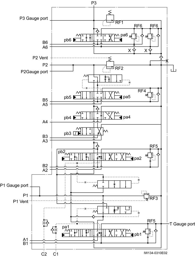
1.1 Hydraulic symbols
Thread size and tightening torque
B-8
1.4
B-8
Hydraulic Pilot Control Valve (Swing, Elevating, Telescoping, Winch)
B-8
B-8
Hydraulic Pilot Control Valve (Swing, Elevating, Telescoping, Winch)
1.5 Telescoping selection assy
Thread size and tightening torque
Hydraulic Pilot Control Valve (Swing, Elevating, Telescoping, Winch)
Hydraulic Pilot Control Valve (Swing, Elevating, Telescoping, Winch)
Thread size and tightening torque
B-8
B-8
Hydraulic Pilot Control Valve (Swing, Elevating, Telescoping, Winch)
Hydraulic Pilot Control Valve (Swing, Elevating, Telescoping, Winch)
1.11
B-8. B-8. Hydraulic Pilot Control Valve (Swing, Elevating, Telescoping, Winch)
Thread size and tightening torque
Thread size and tightening torque
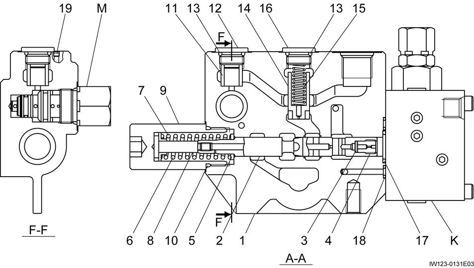
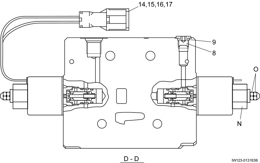
Hydraulic Valve (Pilot Pressure)
B-9 Hydraulic Valve (Pilot Pressure)
[NOTICE]
There is a case that the appearance and so on differ from the parts for this machine. Although there is not so much difference in functions and disassembly procedures, make sure of the serial number of this machine and the part sales unit described in the parts catalog before starting disassembling operations.
1. Structure
Hydraulic symbols
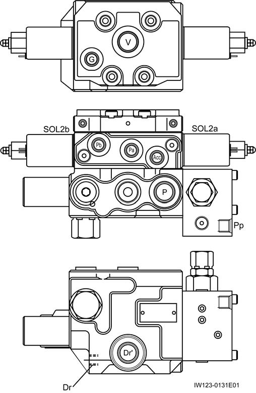
1.1 General view (external view)
Hydraulic Valve (Pilot Pressure)
Thread size and tightening torque
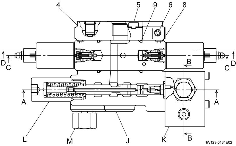
1.2 General view (section view)
1.3 Supply section assy
Hydraulic Valve (Pilot Pressure)
Thread size and tightening torque
Hydraulic Valve (Pilot Pressure)
Thread size and tightening torque
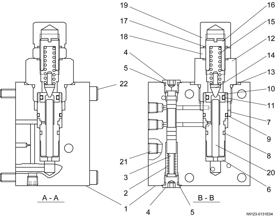
Hydraulic Valve (Pilot Pressure)
1.6 Pressure reducing valve
Hydraulic Valve (Pilot Pressure)
Check Valve (Gauge Isolator)
B-10 Check Valve (Gauge Isolator)
[NOTICE]
There is a case that the appearance and so on differ from the parts for this machine. Although there is not so much difference in functions and disassembly procedures, make sure of the serial number of this machine and the part sales unit described in the parts catalog before starting disassembling operations.
1. Structure
Hydraulic

