13 minute read
Assembly Adjustment (Traveling Device)

from Tadano Faun GR-300EX-2 Rough Terrain Crane (Circuit Diagrams and Data) Service Manual SN 561384

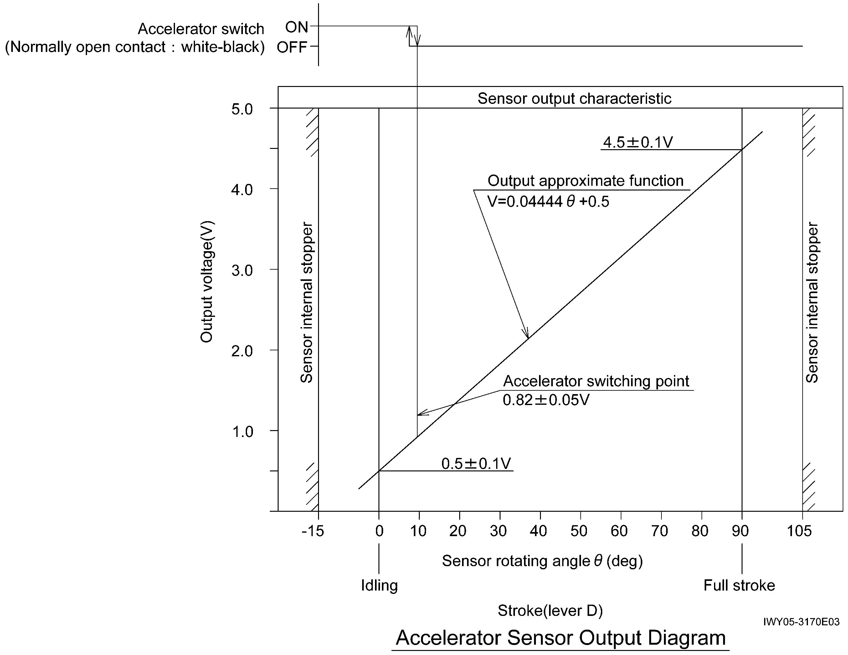
Accelerator sensor output diagram
Advertisement
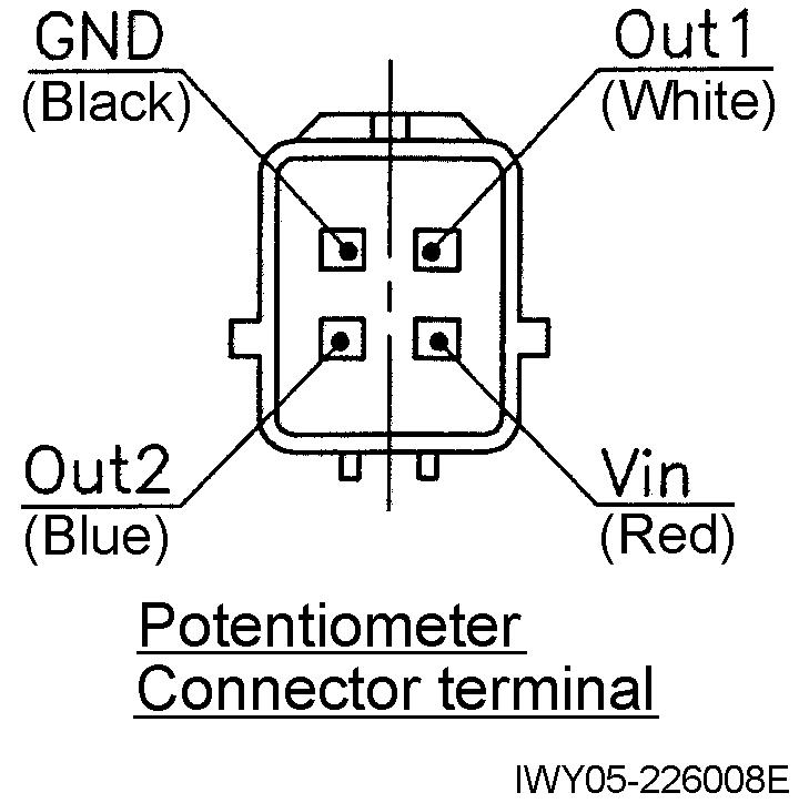
Accelerator sensor handling note
1. Force must not be applied to the sensor internal stopper when you adjust the nut for the sensor shaft fixation.
(Do not receive turning effort with the stopper when you turn the nut in the direction of the stopper from the state that the shaft stops with the stopper.)
2. Do not touch the terminal directly because the static electricity tolerance of the sensor is weak. (Execute it after removing static electricity as it touches other metal parts when it is necessary to touch the terminal.)
Assembly Adjustment (Traveling Device)
3. Parking brake adjustment
3.1 Connecting the parking brake and brake chamber
(1) Shift the rod of the brake chamber to the end of its stroke. (Use air pressure to move it to the end of its extension stroke.) Then adjust the position of end, connect the chamber and brake lever.
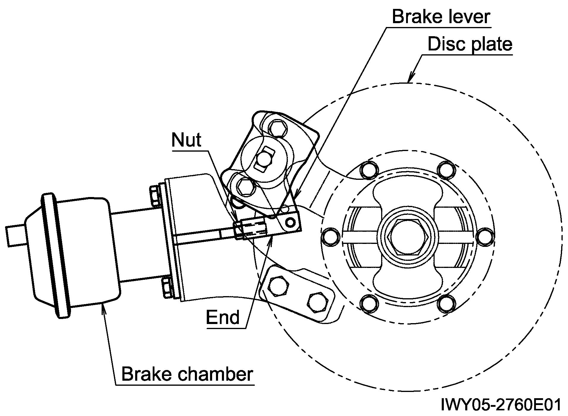
(2) After connecting, check that the clearance between the pad and disc plate becomes approx. 0.2 mm (0.008 in) per side. Then lock in place with the nut.
* Operating stroke of the brake lever: 16 to 20 mm (0.63 to 0.79 in)
4.2 Adjusting the steering angle
1. Jack up the vehicle. Operate the steering cylinder 2 to 3 times with 4-wheel steering (to bleed air out from the cylinder).
2. Before adjusting the steering angle, use a side-slip tester to check that the amount of tire side-slip is no more than ±5 mm (±0.197 in) for both the front and rear tires.
3. If it is more than ±5 mm (±0.197 in), loosen the bolts that fasten the left and right tie-rod ends. Then rotate the tie-rod and adjust the toe-in.
4. Jack up the vehicle on a level road surface so that the height of the left and right tires is the same. Use the steering angle m easurement jig to adjust the steering angle in direction A to [θ] at stopper bolt X, and in direction B to [θ] at stopper bolt Y.
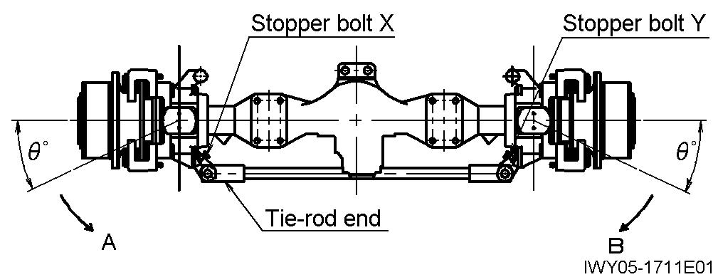
5. Adjust the rear wheels as the procedures of the front wheels.
4. Tire and steering angle adjustment
4.1 Tire air pressure
Unit: kPa (kgf/cm 2) {psi}
Spec. No.: GR-350-2 and GR-300E-2
Tire size θ (°)
20.5×25-24PR 22
445/95R25 26
Assembly Adjustment (Traveling Device)
5. Engine speed (and governor setting)
[NOTICE]
Before checking the engine speed, run the engine to warm it up. (Light weight grease should reach approximately 50°C (122°F).)
1. No-load Max. speed
• PTO - OFF : 2665 ± 50 min-1
• PTO - ON : 1900 min-1
2. Idling speed : 700 ± 50 min-1 (PTO - OFF)
3. Stall speed
(1) Set the switches and levers as described below.
• PTO switch : OFF
• Shift lever : 2nd gear
• Drive speed selector switch : 4WD High
• Service brake : ON
(2) Depress the accelerator pedal all the way. Check the speed when the engine speed has stabilized. Max. speed standard when stalled: Approx. 2010 min-1
6. Torque converter and transmission
6.1 Maximum allowable speed
[NOTICE]
Engine speed: 2500 min-1
Check the meter indication.
Pay attention to the tachometer and do not overrun the engine. (Max. 2740 min-1)
Drive-speed selection must be done with the vehicle at a complete stop and with the brakes not applied.
The mechanism does not allow 2WD selection in Lo position.
6.2 Adding oil to the torque converter and transmission
[NOTICE]
When checking the oil level, turn PTO OFF and turn the air conditioner OFF. Check at an oil temperature of 50°C (122°F), once the oil level has stabilized after the engine is started.
Do not add too much or too little oil. Do not allow dust or water to enter when adding oil.
1. W ith the engine stopped, add oil to the oil injection port in the top of the T/C, to the prescribed level on the T/M oil level gauge.
2. Put the T/M in neutral and start the engine. While idling (700 min-1), continue to add oil. Check that the oil level has stabilized within the range indicated by the * mark on the T/M oil level gauge.
Total oil volume: approx. 33 L (8.7 gal)
Assembly Adjustment (Traveling Device)
7. Braking force
7.1 Parking brake force
1. The parking brake force must be 20% or more of the vehicle weight. Check that both the front and rear braking forces.
Spec No.
GR-350-2
GR-300E-2
Required braking force 53.9 kN {5500 kgf} (12128 lbf) or more
7.2 Service brake force
1. The service brake force must be 25% or more of the vehicle weight. Check that the front service braking force.
Spec No.
GR-350-2
GR-300E-2
Required braking force 67.4 kN {6875 kgf} (15159 lbf) or more
Required front brake force (for reference) 33.4 kN {3410 kgf} (7519 lbf)
Required rear brake force (for reference) 34.0 kN {3465 kgf} (7640 lbf)
Check that the difference in braking force between the left and right wheels is 9.2 kN {940 kgf} (2073 lbf) or less.
8. Adjusting the headlight light axes
(1) Turn the switch to the high beam side.
(2) Use a tester and adjust as follows.
Left-right direction: 0° ± 0.5°
Up-down direction: 0.5° ± 0.2° (downward)
(3) Check that the brightness of 15,000 cd is achieved when measured by a tester.
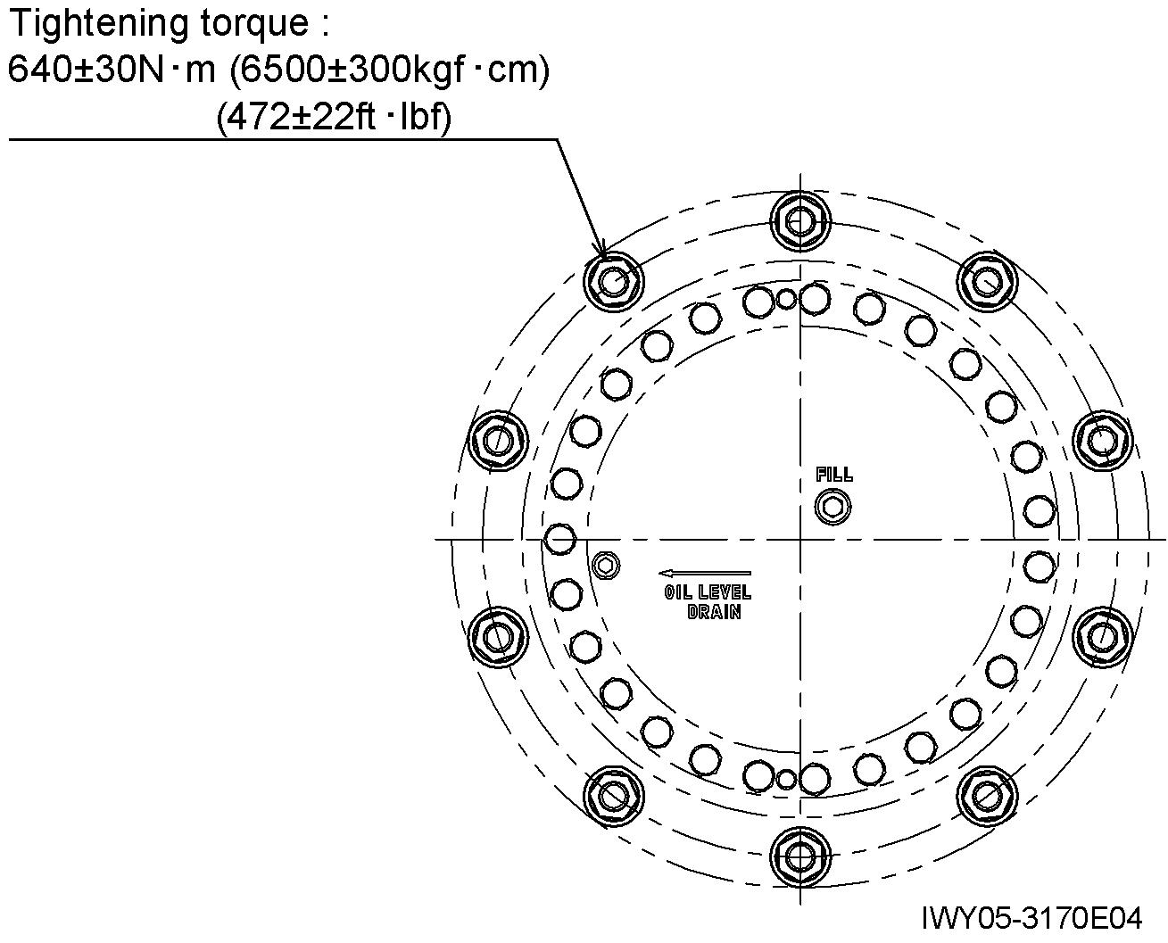
9. Retightening the hub nuts
• Retighten the hub nut with the tightening torque of 640 ± 30 N m {6500 ± 300 kgf cm} (472 ± 22 ft lbf)
• Retighten hub nuts after checking the brake force (See the section 7.), and before shipment. (The hub nuts must be settled before retightening. When the load is applied to the wheel mounting sections during braking force check, the nuts settle.)
• Put the retightening torque for the hub nuts (the torque of the latest tightening) on the hub nut torque check record.
Operation Check (Crane Operation)
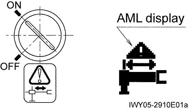
Y - 8 Operation Check (Crane Operation) 1. Outrigger status indicator
Main switch : ON
PTO : ON
Shift lever : Not in N position
Operate the outrigger extension/retraction switch.
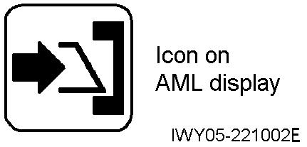
Icon flashes on the AML display.
Press all outrigger control switch.
Outriggers do not operate.
Main switch : ON
PTO : ON
Shift lever : N position
Operate the outrigger extension/retraction switch.
Icon flashes on the AML display.
Press all outrigger control switch.
Outriggers operate.
Operation Check (Crane Operation)
2. Hoisting [Condition]
• Load : None
• Engine speed : Approx. 700 min-1 to medium speed
[Procedure]
1. Shift the boom telescoping lever to full stroke first.
2. Make sure that the main winch moves slowly while the auxiliary winch lever is slightly operated.
3. Make sure that the main winch does not move while the auxiliary winch lever is operated to full stroke.
3. Backward stability control
[NOTICE]
Extend the outrigger, and set up the machine horizontally.
1. Select the on-rubber for outrigger set status on the AML.
2. The boom raising operation must be stopped at 71° automatically.
3. The boom lowering must be available.
4. Outrigger emergency setting
5. Jib
1. Make sure that the overwind (two-blocking) function does not work while the jib set status is registered.
2. Check the jib lock indicator lamp.
• Make sure that the lamp is lit when the jib is in “set state” (the jib stowed detection switch (CN572) is not activated).
1. Turn the switch of the upper right panel in the cab ON.
2. Icon flashes on the AML display.
3. Check that the extension width smaller than the detected value can be registered on AML manually.
• Make sure that the lamp is not lit when the jib is in “stowed state”
Operation Check (Crane Operation)
6. Boom Telescoping Control
[Boom length: 9.7 - 31.0 m (31.8 - 101.7 ft)]
S1: Emergency telescoping switch for 3rd to top boom sections
S2: Emergency telescoping switch for 2nd boom section
S7: Extension switch for 3rd to top boom sections
L7: Full-retraction detection limit switch for 3rd to top boom sections
Extension
9.7 m (31.8ft) boom (base)
Telescoping possible only for 2nd boom section.
Boom length: 16.65 m (54.6 ft)
Switch S7 : OFF
Retraction
Approx. 24.38 m (80.0 ft) boom
3rd to top boom sections retract.
Switch L7: ON
2nd boom section retracts. (Even if stroke remains for the 3rd to top boom sections at this time, the hydraulic valve orifice causes them to fully retract.)
Emergency telescoping
9.7 m (31.8 ft) boom (base)
Turn the AML override key to the emergency side, and turn PTO switch to “OVER RIDE” side.
2nd boom section can be moved to the stroke ends.
(AML works on the basis of performance with 16.8-m boom.)
Switch S7: ON Extension is possible of 3rd to top boom sections.
(When switch L7 turns OFF, AML begins to work on the basis of performance with 24.38-m boom.)
With switch S1 pressed, extend the 3rd, 4th, and top boom sections by approximately 1m (3.3ft) each.
With switch S2 pressed, fully extend the 2nd boom section.
At this time, check that the error contents are as follows until the boom length reaches 16.4 m (53.8 ft).
With switch S2 pressed, retract the 2nd boom section and reduce the boom length to 15.8 m (51.8 ft) or less. At this time, because the No. 2 cylinder is connected to the tank through the hydraulic valve orifice, the 3rd to top boom sections may also retract.
With switch S1 pressed, retract the 3rd to top boom sections.
Operation Check (Crane Operation)
7. Suspension lock [NOTICE]
Condition
• Crane status for check : On-rubber configuration : Boom forward (over-front)
• Engine speed : Approx.700 min-1
• Vehicle speed : 0 km/h
• Shift lever : N position
[NOTICE]
While PTO is disengaged (OFF), suspension can be locked and unlocked. While PTO is engaged (ON), suspension can be locked but cannot be unlocked.
[Procedure]
1. Press the suspension lock switch to the lock side.
2. Check that after 1 second, the indicator lamp begins to flash.
3. Check that the lamp stops flashing and remains lit 6 seconds after it starts flashing. Then release the switch.
4. Stop the engine. Check that the suspension lock cylinders are fully retracted (4 locations).
5. Restart the engine. (At this time, check that the indicator lamp is lit)
6. Press the suspension lock switch to the unlock side.
7. Check that after 1 second, the indicator lamp is not lit.
8. Stop the engine. Check that the suspension locks are released (4 locations).
Operation Check (Crane Operation)
8. Warning [NOTICE]
For the location of the buzzers, refer to "Z-11 Electric Parts Location Diagram (Upper), 1. Inside cab "
Item Warning buzzer Sound Checking procedure
AML limit Buzzer 3 (CN818)
Overwind (two-blocking) warning Buzzer 4 (CN817)
Outrigger operation switch detection
Buzzer 1 (CN815, CN816)
• 280Hz
• Continuous low tone
• 2300Hz
• Continuous high-low tones
• 2300Hz • Intermittent beeping
9. Rope run-out detection check
Occurs at 100% when main switch is ON and PTO switch is ON. (Intermittent low tone sound occurs at 90% and above.)
Occurs when the overwind (two-blocking) switch contact of either the main or auxiliary winch is turned OFF by winch hoist-up operation.
Sounds when either the outrigger extension/retraction or jack slide selector switch has been left in any position other than neutral 10 seconds after operation is completed.
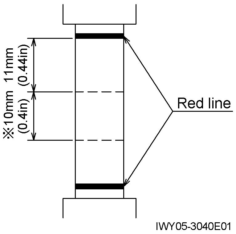
Check that the rope run-out detection activates and the winch stops when the wire rope on the winch drum decreases close to 3 wraps.
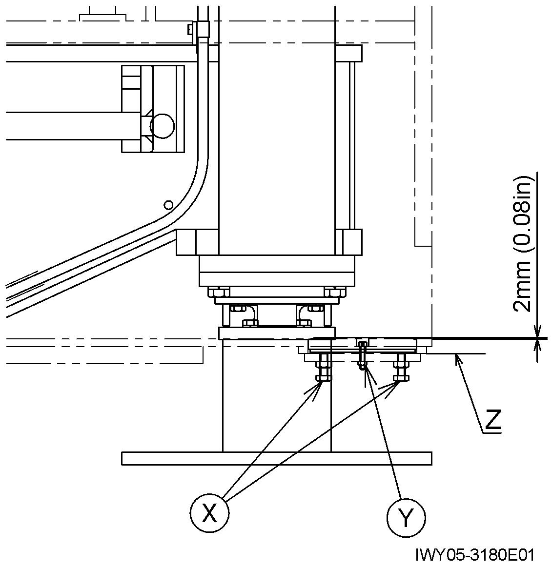
10. Outrigger slide plate adjustment
1. With the outriggers fully retracted, install the slide plate and the plate into the outrigger box.
2. Adjust the slide plate with the bolt X so that the slide plate is 2mm (0.08 in) away from the upper surface of outrigger box bottom plate.
3. If the slide plate is 2 mm (0.08 in) or more away, make sure that the bolt X does not protrude beyond the plane Z.
4. Tighten the bolts of Y slightly to fix the slide plate. Then tighten the nuts of Y hard.
5. Tighten the nut of X.
Operation Check (Crane Operation)
11. Eco mode operation check
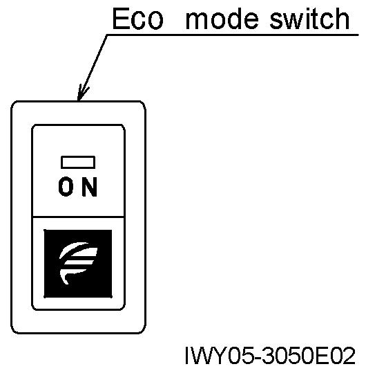
While the PTO is engaged, select the Eco mode 1 and Eco mode 2, and depress the accelerator pedal fully. Then check that the maximum engine speed lowers while the respective mode is selected.
Eco mode Max. engine speed (min-1)
OFF Approx. 1900
1 Approx. 1550
2 Approx. 1350
Use the AML to select the Eco mode 1 or Eco mode 2. The maximum engine speeds above listed are for reference.
Operation Check (Traveling Device)
Y - 9 Operation Check (Traveling Device)
1 Exhaust brake (EXB)
1. Turn on the EXB brake, and keep the engine idling. (The pilot lamp remains lit.)
2. Check pattern
[NOTICE]
Check whether EXB is operating or not from the engine noise and from the movement of the air cylinder.
Engine speed does not exceed 1200 min-1 by adjustment of the idle volume. The lock up is engaged when the gear position is in 2nd or above, the engine speed is 1100 min-1 or above and EXB is ON.
Seq. Operation EXB
Release the accelerator pedal and move the shift lever into the N position.
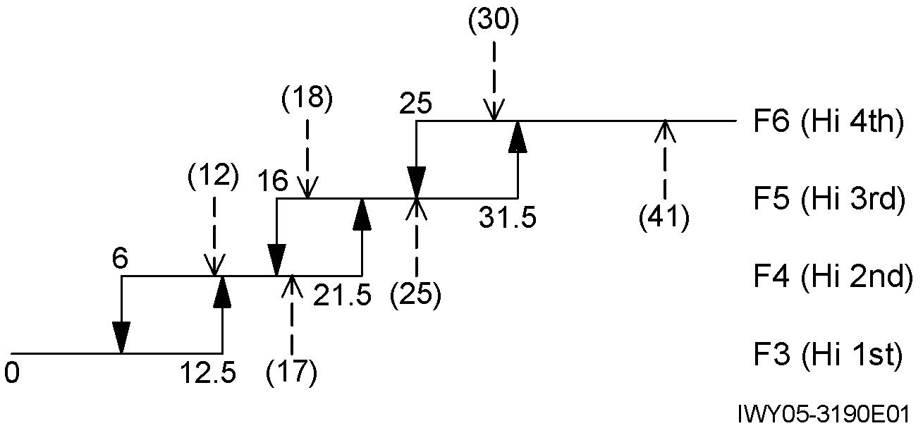
2. Automatic transmission [1 km/h = 0.6214 MPH]
[NOTICE]
Numbers indicate speedometer readings (units: km/h)
( ) Indicates lock-up ON and OFF values.
[High position]
1
Adjust the engine speed to 1,000 min-1 or higher using the idle volume.
(The pilot lamp illuminates.)
Return the engine speed to idling and move the shift lever from N to D.
Manual shift
2
Adjust the engine speed to 1,000 min-1 or higher using the idle volume.
3 Depress the accelerator pedal. OFF
4 Release the accelerator pedal. ON
5 Adjust the engine speed to 1,000 min-1 or lower using the idle volume OFF
6 Adjust the engine speed to 1,000 min-1 or higher using the idle volume.
7 Return the engine speed to idling, and move the shift lever to N. OFF
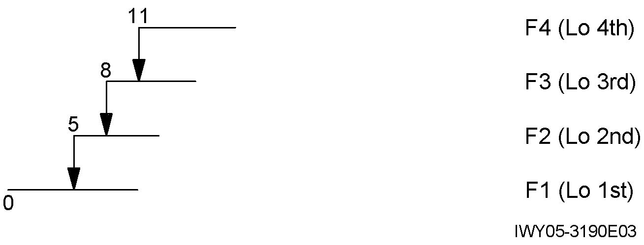
[Low position]
[NOTICE]
No automatic shift in Low position.
Operation Check (Traveling Device)
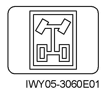
3. Steering mode change
Change the steering mode switch to 4- wheel or crab steering. Turn the steering wheel, and check the steering.
4. Emergency switch
Check that the lamp in the right bottom of the instrument panel is ON, except when rear wheels are out of straight-ahead condition.
Make the rear wheels in the straight-ahead condition.
Check that the lamp is OFF.
Push the 2-wheel steering mode selector switch.
1. Emergency gear shifting procedure
After turning the emergency transmission switch to ON, make sure that gear shift lever position “D”, “3”, “2” and “1” are assigned to the 4th gear, 3rd gear, 2nd gear and 2nd gear respectively for traveling.
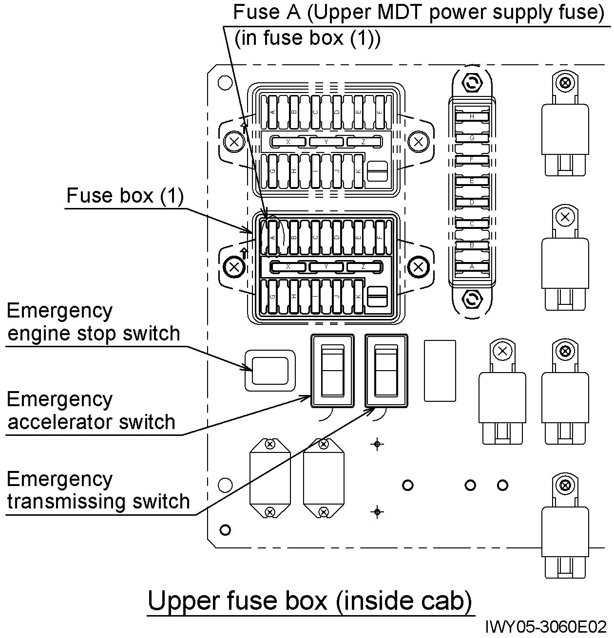
2. Emergency accelerator
With the starter key in the “OFF” position, disconnect the fuse A (upper MDT power supply fuse).
Turn the emergency accelerator switch to ON and start the engine. Make sure the engine revolution rises to maximum when the accelerator pedal is depressed even slightly.
3. Emergency engine stop
Make sure that the engine stops when the emergency engine stop switch is pulled.
Operation Check (Traveling Device)
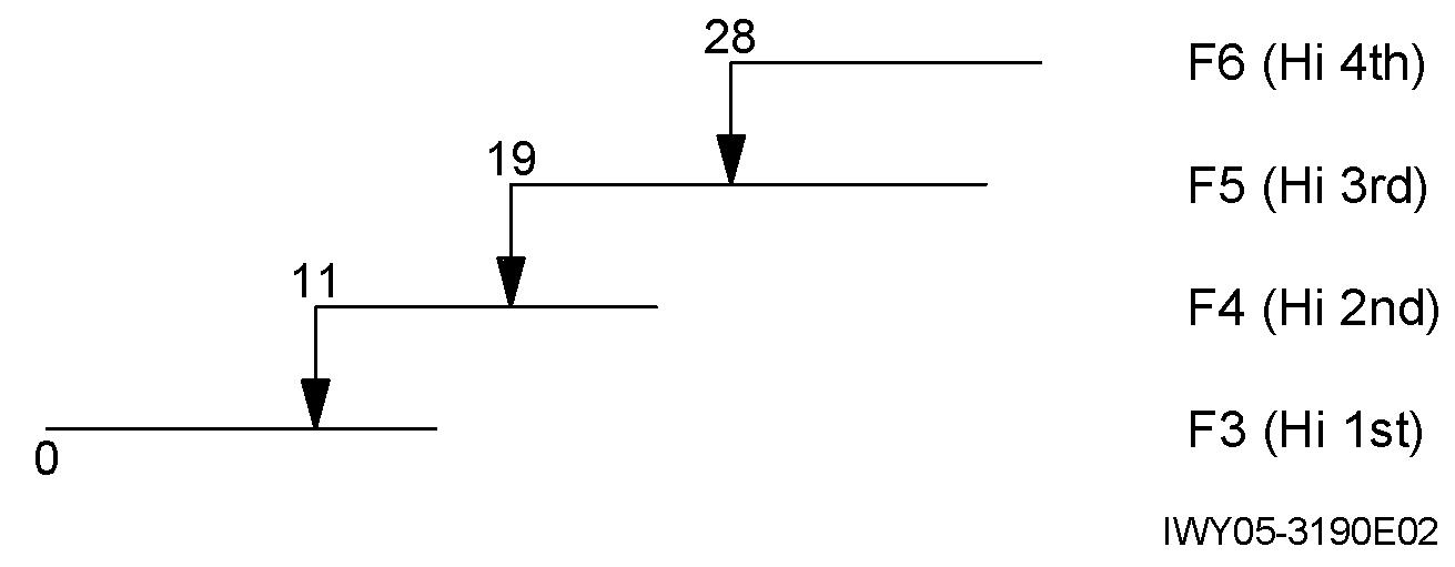
5. Overshift prevention [1 km/h = 0.6214 MPH]
[NOTICE]
Jack up the vehicle and shift to 4WD High position. Perform the operations below and check the shift position with the combination meter.
1. Move the shift lever to “D” and increase speed to 32 km/h or more. Check that transmission shifts to 4th gear (display: D).
2. Gradually reduce speed. Maintain a speed of 30 km/h. Move the shift lever to “3.” Check that transmission does not downshift (display: D).
3. Gradually reduce speed. Check that transmission downshifts to 3rd gear when the speed is 28 km/h (display: 3).
4. Maintain a speed of 21 km/h. Move the shift lever to “2.” Check that transmission does not downshift (display: 3).
5. Gradually reduce speed. Check that transmission downshifts to 2nd gear at 19 km/h (display: 2).
6. Maintain a speed of 13 km/h. Move the shift lever to “1”. Check that transmission does not downshift (display: 2).
7. Gradually reduce speed. Check that transmission downshifts to 1st gear at 11 km/h (display: 1).
Operation Check (Traveling Device) 6. Warning [NOTICE]
For the location of the buzzer, refer to "Z-11 Electric Parts Location Diagram (Upper), 1. Inside cab " [1 km/h = 0.6214 MPH]
Low air pressure and parking brake applied buzzer 1 (CN815, CN816)
Engine overrun buzzer 1 (CN815, CN816)
• 2300 Hz
• Continuous beep
• 2300 Hz
• Intermittent beeping
Buzzer does not sound when the following conditions are met. It sounds at all other times.
1. Air pressure is 540 kPa (5.5 kgf/cm 2) (78.3 psi) or less. From parking OFF, main switch is turned ON.
2. Parking is ON, and shift lever is out of N position.
The mechanism sounds at engine speed of 2740 min-1. There is not need to check it. Turns OFF at 2600 min-1
Check is unnecessary because you cannot attach a step-up gear.
[Reference]
Speed warning buzzer 1 (CN815, CN816)
• 2300 Hz
• Continuous and intermittent sounds
During accelerating:
Speedometer reading 62 km/h: Intermittent sound
68 km/h: Continuous sound
Torque converter low pressure buzzer 1 (CN815, CN816)
2WD/4WD select buzzer 1 (CN815, CN816)
7. Speedometer
• 2300 Hz
• Continuous beep
• 2300 Hz
• Continuous beep
During decelerating:
Speedometer reading 59 km/h: Intermittent sound
56 km /h: OFF
Buzzer sounds if the torque converter pressure is 1.0 MPa (10.2 kgf/cm 2) (145 psi) or less while the parking brake is OFF.
Sounds if vehicle speed exceeds 1.0 km/h when 2/4-wheel switch condition disagrees with 2/4-wheel indication in the meter panel.
(1 km/h = 0.6214 MPH)
When the actual traveling speed of the vehicle is V2, the reading of the speedometer (V1) shall meet the following formula:
0 V1 -V2 V2 / 10 + 6
Ex. Case of a vehicle of [45km/h < Vmax 55km/h]
V1 shall be 80% of Vmax. V1 = 40 km/h
When the speedometer reading is 40 km/h, the tester speed V2 shall be as follows:
30.91 km/h V2 40 km/h
Inspection and Maintenance
Y - 10 Inspection and Maintenance
1. Refer to “Inspection and Maintenance” in “Operation and Maintenance Manual” of its applicable crane.
2. Maintenance of Line Filter
[NOTE] For the location of the parts, see "Z-1.1 Comparison table of hydraulic parts (Part No., Part name and Location)”, "Z-7 Hydraulic Parts Location Diagram (Upper)" and "Z-8 Hydraulic Parts Location Diagram (Lower)" in the chapter Z.
Boom Connecting Pin and Thread Size Table
Y - 11
Boom Connecting Pin and Thread Size Table
Note: “ ” means that more than one spec. No. are applicable.
(Unit: mm) (1 mm = 0.039 inch)
Applicable spec. No