3 minute read
Air Bleeding Procedure

from Tadano Faun GR-300EX-2 Rough Terrain Crane (Circuit Diagrams and Data) Service Manual SN 561384

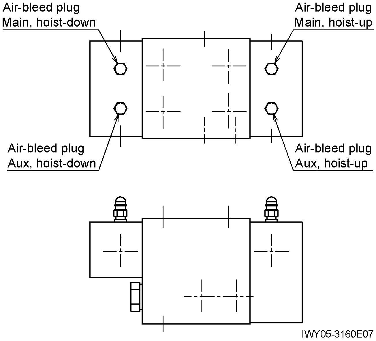
7. Positive control circuit
While any of the crane operations described in 6 is performed, loosen the air -bleed plug near the lower pump to bleed the positive control circuit You can bleed the circuit at the same time with pilot circuit bleeding.
Advertisement
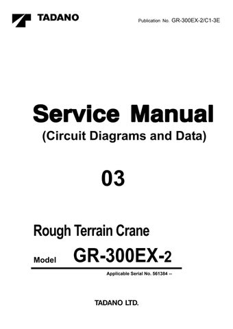
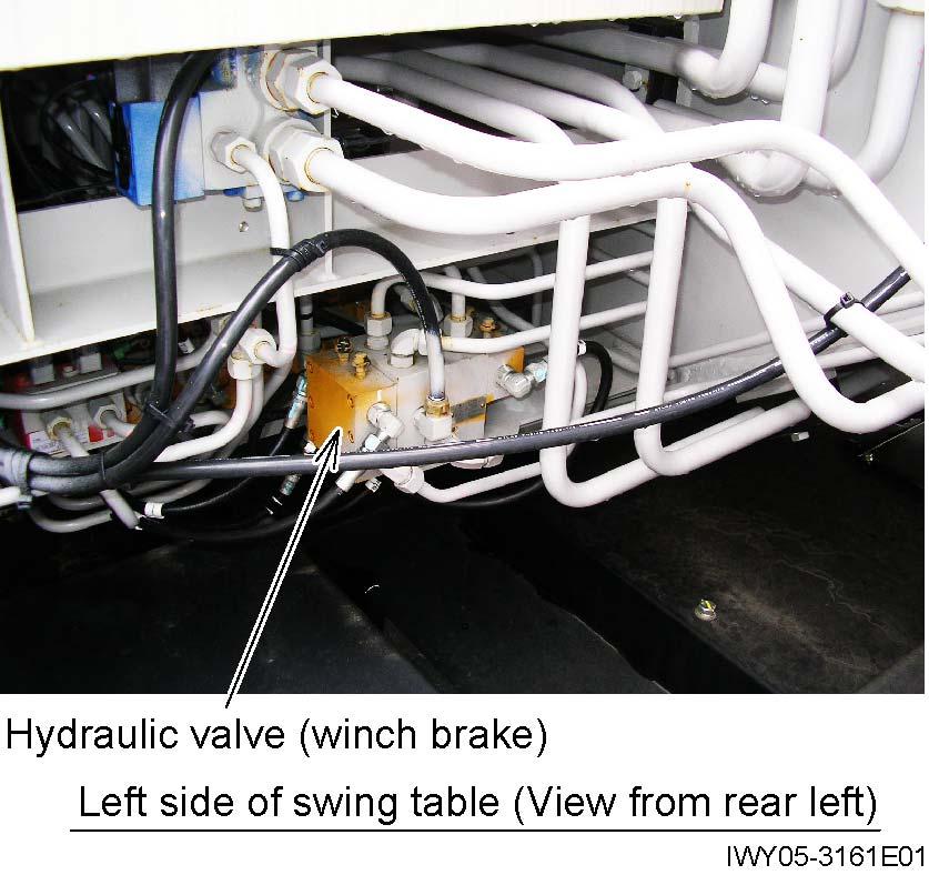
8. Hydraulic valve (winch brake)
[NOTICE]
Bleed this valve after the pilot circuit (hydraulic pilot control valve) (See the section 6.) and the positive control (See the section 7.) are bled.
Conditions
Engine speed : Idling (700 min-1)
PTO : ON
1. Open the air-bleed plug and move the winch lever fully to the end of its stroke in the direction corresponding to the plug.
2. When there are no more bubbles in the oil that flows out, tighten the plug while the oil continues to flow. Then return the lever to the neutral position.
Adjusting Procedure (Electric)
Y - 5 Adjusting Procedure (Electric)
1. 3rd / top boom full retraction detection switch (CN859)

Adjust the switch position so that its contact is shifted (opened/closed) when the top boom section is extended/retracted beyond the position where it is 5 to 8 mm (0.2 to 0.31 in) longer than its fully retracted length.
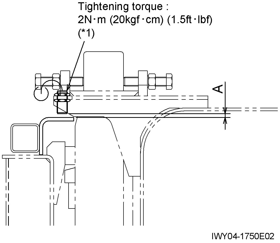
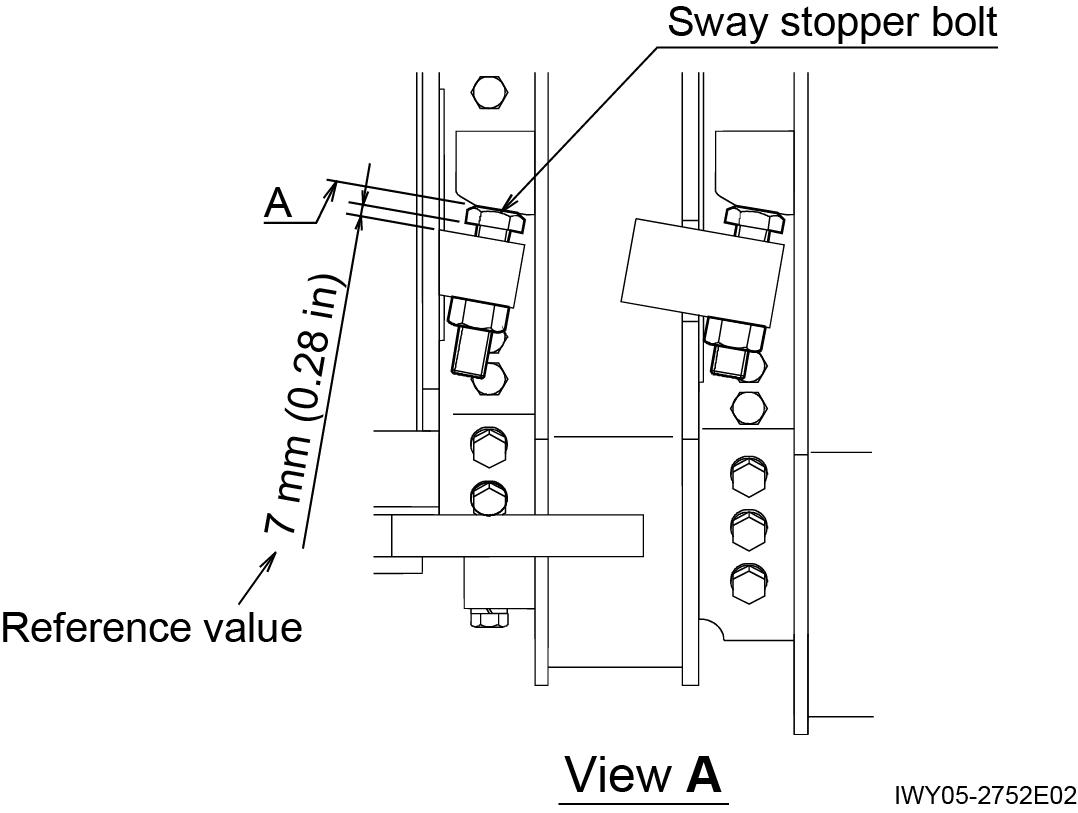
2. Jib stowed detection switch (CN572)
Adjust the switch position so that the dimension A becomes 7 mm (0.28 in) with the jib stowed.

(*1): Apply the screw locking agent (Three-Bond 1401 or the equivalent).
[NOTICE]
Make sure that the green LED lights up when the switch is activated.
Adjusting Procedure (Electric)
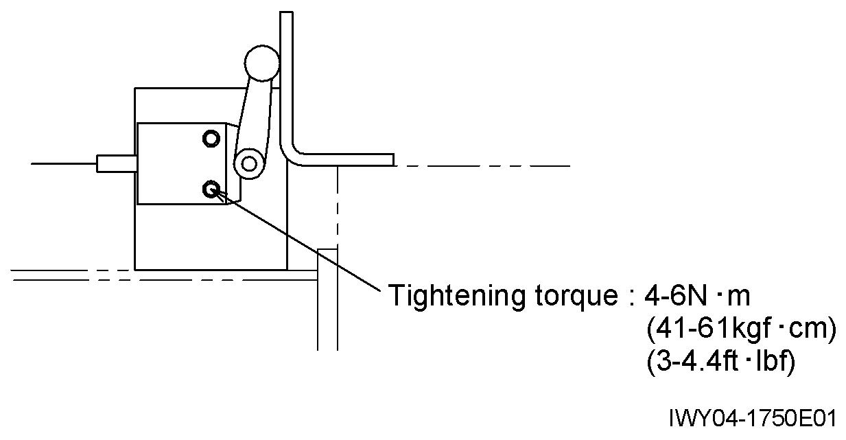
3. Main winch drum rotation detection switch (CN591)
Adjust the switch position so that the dimension A becomes 2.5 ± 0.5 mm (0.1 ± 0.02 in)
(*1): Apply the screw locking agent (Three-Bond 1401 or the equivalent).
[NOTICE]
Make sure that the green LED lights up when the switch is activated.
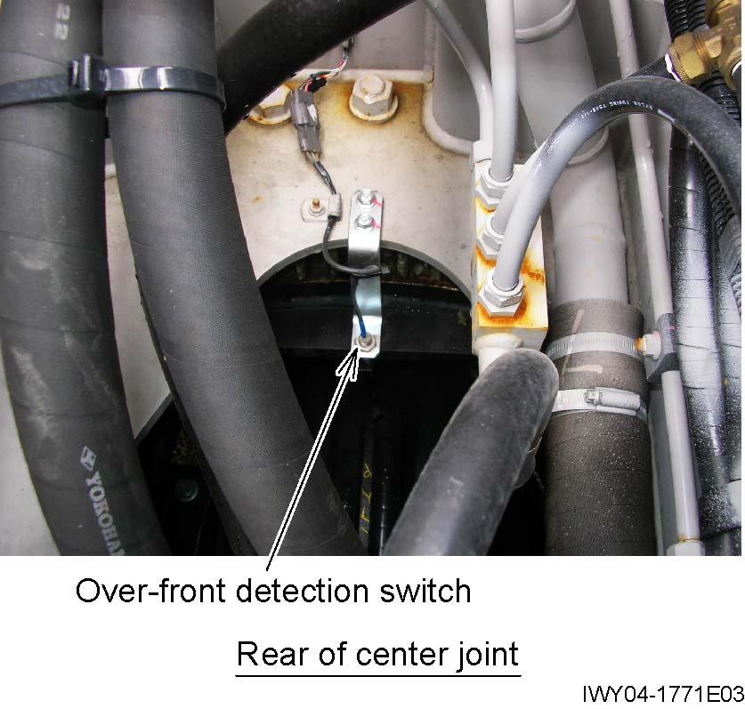
5. Over-front detection switch (CN521)
Fully retract the boom and swing it to the over-front. Insert the swing lock pin and set the boom angle to 0°. Then, adjust the switch position so that the dimension A becomes 2.5 mm (0.1 in).
(*1): Apply the screw locking agent (Three-Bond 1401 or the equivalent).
[NOTICE]
Make sure that the green LED lights up when the switch is activated.
4. Aux. winch drum rotation detection switch (CN592)
Follow the same procedure as that in MAIN WINCH DRUM ROTATION DETECTION SWITCH (CN591).


Adjusting Procedure (Electric)

Before the adjustments below, reduce the clearance B to minimum, and adjust switch position so that the dimension A becomes 2.5 mm (0.1 in).
(*1): Apply the screw locking agent (Three-Bond 1401 or the equivalent).
Set the rear wheels in a straight-forward position, and adjust the switch position so that the dimension A becomes 3 mm (0.12 in).
(*1): Apply the screw locking agent (Three-Bond 1401 or the equivalent).

[NOTICE]
Make sure that the green LED lights up when the switch is activated.
Adjusting Procedure (Electric)
8. Wire rope run-out detection switch (main (CN595) and aux. (CN596))
△ 0 344-446-90000
△ 0 344-447-00000
Adjust the roller assy position by the bolt so that the dimension A becomes 5 mm (0.2 in), and lock the bolt with a nut.
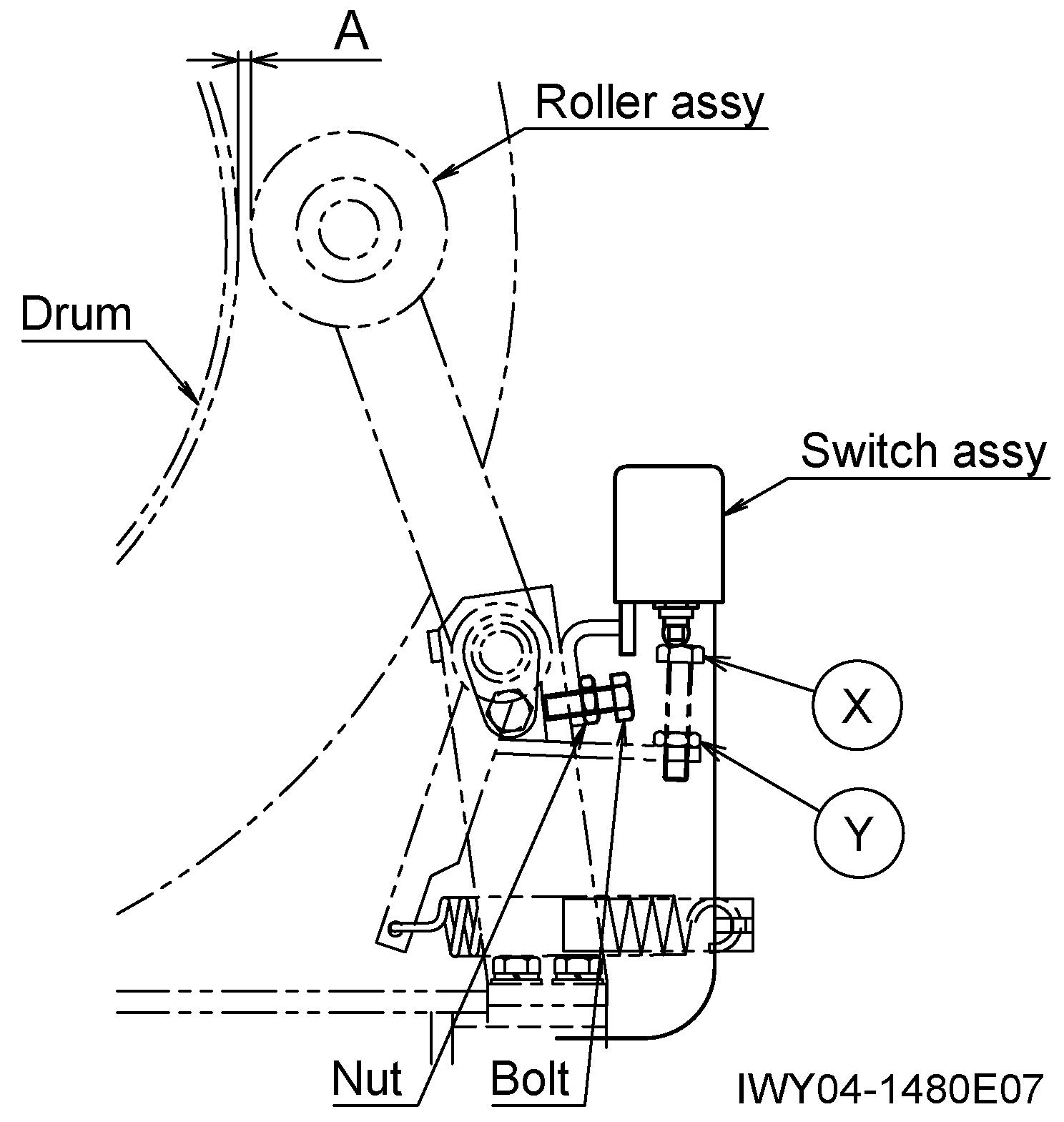
Squeeze the roller assy of switch upward further by 1.5 mm (0.06 in) after the switch’s contact is shifted (opened/closed).
(One turn of X bolt makes the switch move upward or downward by 1.5 mm (0.06 in).) Then lock X bolt with Y nut.
(Note)
• Make the head surface of X bolt flat beforehand
• Use X bolt and Y nut of roller assy.
Assembly Adjustment (Crane Operation)
Y - 6 As sembly Adjustment (Crane Operation)
1. Adjusting boom telescoping wire ropes
1. After assem bling each boom section and adjusting the slide plate by adding or removing shims, retract the boom fully. (Keep the wire rope free.)
[NOTICE]
Sheave at the head of the 3rd boom section
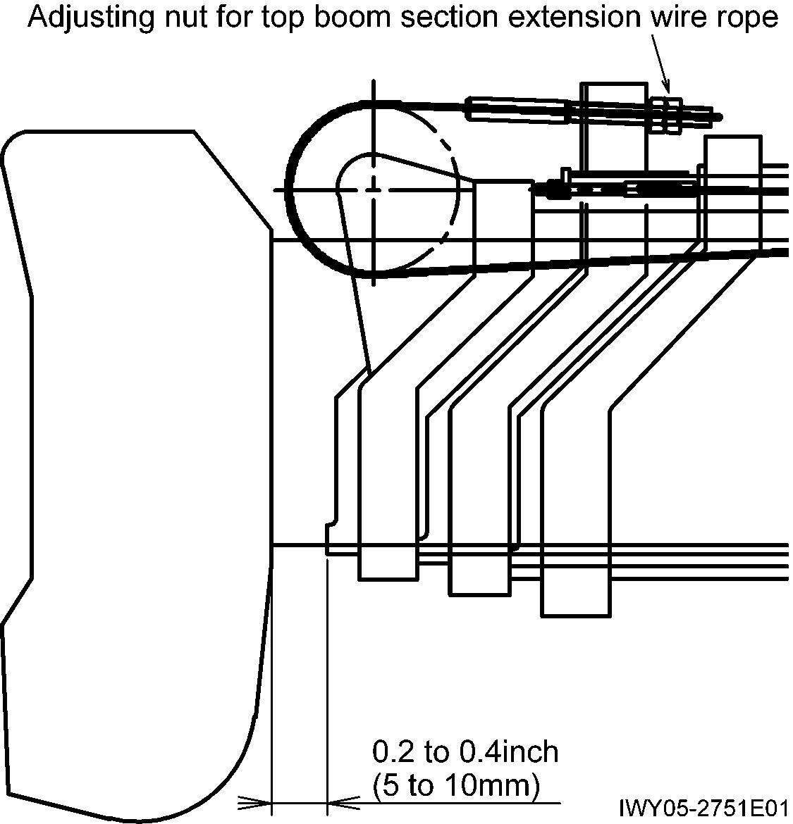
Top boom section extension wire rope
Fix at the head of the 2nd boom section
Top boom section retraction wire rope
Fix at the rear end of the top boom section
Sheave at the rear end of the 3rd boom section
Top boom 3rd boom 2nd boom Base boom
Loosen the sway stopper bolt on the bottom of each boom section until it is out of contact with the support. IWY05-0590E02
2. Tighten the right and left adjustment nuts for the top boom section extension wire rope alternately. Pull out the top boom section for 5 to 10mm (0.2 to 0.4in).
Assembly Adjustment (Crane Operation)
3. Tighten the adjustment nut for top boom section retraction wire rope until the top boom section stopper seats against the 3rd boom section head. IWY05-0590E05
Adjusting nut for top boom section retraction wire rope
4. After checking the contacting condition of stopper for each boom section, fix adjuster section for each extension and retraction wire rope with two nuts.
5. Adjust the sway stopper bolt for each boom section.
[NOTICE]
Apply thread locking agent to the sway stopper bolts, tighten them. Let the bolts touch the surface A lightly, and then lock the bolts with nuts.