1 minute read
Assembly Adjustment (Traveling Device)

from Tadano Faun GR-300EX-2 Rough Terrain Crane (Circuit Diagrams and Data) Service Manual SN 561384

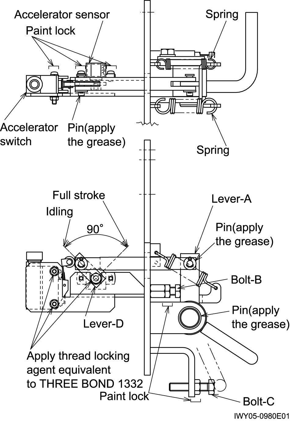
2.2 Accelerator sensor assembly and adjustment
[NOTICE]
Advertisement
Do not touch the terminal directly because the static electricity tolerance of the sensor is weak. Force must not be applied to the sensor internal stopper when you adjust the nut for the sensor shaft fixation.
(Do not apply turning force to the stopper when the nut is turned toward the stopper from the condition that the sensor shaft is halted by the stopper.)
1. Installation of lever D
Press-fit it in the thrust at the time of tightening the nut for the lever fixation so that the load is not applied in the direction of thrust of the sensor axis.
2. Installation of spring
Before installing the spring, secure the lever A using the bolt B. Otherwise, the sensor may go to the stroke end while the spring is installed and excessive force may be applied to the stopper inside the sensor. (When installing the bolt, make the bolt head protrude further than the regular position, that is, to allow the accelerator pedal to be depressed further.)
3. Positioning of lever A
Adjust with bolt B and lock with the nut so that lever A becomes vertical.
4. Positioning of idle side sensor
Adjust the position of the sensor so that each sensor output (Out1 (white-black) and Out2 (blue-black)) becomes 0.5 ± 0.1 V when 5±0.1 V is impressed to VIn (red-black).
5. Positioning of accelerator switch
Adjust the installation position of the accelerator switch so that accelerator switch change at the position in which each sensor output (Out1 (white-black) and Out2 (blue-black)) becomes 0.82 ± 0.05 V when 5 ± 0.1 V is impressed to VIn (red-black).
6. Positioning of full stroke side stopper
Adjust the position of the sensor with bolt C and lock with the nut so that each sensor output (Out1 (white-black) and Out2 (blue-black)) becomes 4.5 ± 0.1 V when 5 ± 0.1 V is impressed to VIn (red-black).
[NOTICE]
Adjust the bolt so that excessive force should not act on the sensor internal stopper when the sensor reaches the stroke edge.
7. Lock six places shown in Figure with paint after adjustment is finished