3 minute read
Assembly Adjustment ( Traveling Device)

from Tadano Faun GR-250N-2 Rough Terrain Crane (Circuit Diagrams & Data) Service Manual SN FB4745 - PDF

4. Tire air pressure and steering angle adjustment
4.1 Adjusting the steering angle
[NOTICE]
Tire size : 385/95 R 25 170E
Air pressure : 900 kPa {9.00 kgf/cm2} (130.5 psi)
1. Jack up the vehicle and select 4-wheel steering mode. Turn the steering wheel 2 to 3 times to bleed the steering cylinders.
2. Before adjusting the steering angle, use a side-slip tester to check that the amount of tire side-slip is within 3 mm (0.12 in) for both the front and rear tires.
3. If it is out of 3 mm (0.12 in), loosen the bolts that fasten the left and right tie-rod ends. Then rotate the tie-rod and adjust the toe-in.
4. Jack up the vehicle on the level surface (so that the height of the left and right tires is the same). Use the steering angle measuring jig to adjust the steering angle in direction A to 35° ° using stopper bolt A, and the one in direction B to 35° ° using stopper bolt B.
5. Perform the same adjustment for the rear wheels.
5. Torque converter and transmission
5.1 Maximum allowable speed
6. Braking force [NOTICE]
The braking force to be checked is the difference between the measured value when the brake pedal is depressed and the one when the pedal is not depressed.
6.1 Parking brake force
[NOTICE]
Engine speed: 2700 min-1
Check the meter indication.
Pay attention to the tachometer indication and do not overrun the engine. (Max. 2900 min-1)
Drive selection must be done with the vehicle at a complete stop and with the brakes not applied.
The mechanism does not allow 2WD selection in Low-speed drive.
5.2
Adding oil to the torque converter and transmission
[NOTICE]
When checking the oil level, turn OFF the PTO and air conditioner. Check at an oil temperature of 50°C (122°F) when the oil level settles after the engine is started.
Do not add too much or too little oil. Prevent dust and water from entering when adding oil.
1. With the engine stopped, add oil through the oil filler port on the top of the T/C to the prescribed level on the T/M oil level gauge.
2. Put the T/M in neutral and start the engine. While idling (600 min-1), continue to add oil. Check that the oil level settles within the range indicated by the mark on the T/M oil level gauge.
1. Must be 20% of the vehicle weight at least. Check that the front and rear braking forces are 50.2 kN {5120 kgf} (11290 lbf) or more.
6.2 Service brake force
1. The difference in the braking force between the right and left wheels must be 8% of the axle load or less
Check that it is not greater than 7.5 kN {770 kgf} (1698 lbf)
2. Check that the sum of the braking force is 40% of the vehicle weight at least. Check that the front braking force is 63.4 kN {6475 kgf} (14277 lbf) or more.
Check that the rear braking force is 39.9 kN {4080 kgf} (8996 lbf) or more.
6.3 3rd brake force
1. Check that the sum of the braking force of the 3rd brake is 35% of the vehicle weight at least. Front + rear = 87.8 kN {8960 kgf} (19757 lbf)
Assembly Adjustment ( Traveling Device)
7. Adjusting the headlight light axis
[NOTICE]
Before adjusting the headlight light axis, always operate the suspension to make the vehicle level.
The following describes the case of 3-m test. Measure with the A/C OFF.
[NOTICE]
Luminous intensity (4-lamp configuration)
High beam: 10000 cd or more per 1 lamp
225000 cd or less as sum of 4 lamps
Low beam: Not less than 6000 cd, and not more than 14400 cd
7.1 Adjusting the HR-7
1. Turn the switch to the high beam side.
2. Mask the 3 lights other than the one to be adjusted.
3. Adjust so that the maximum brightness is achieved at a position 0.5° D-V from the lamp center when measured by a tester. Horizontal direction: On the vertical plane that includes the lamp center Vertical direction: 0.5° below the horizontal plane that includes the lamp center.
4. Perform the above adjustments for the left and right lights.
7.2 Adjusting the HCR-200
1. Turn the switch to the low beam side.
2. Mask the HCR-200 other than the one to be adjusted.
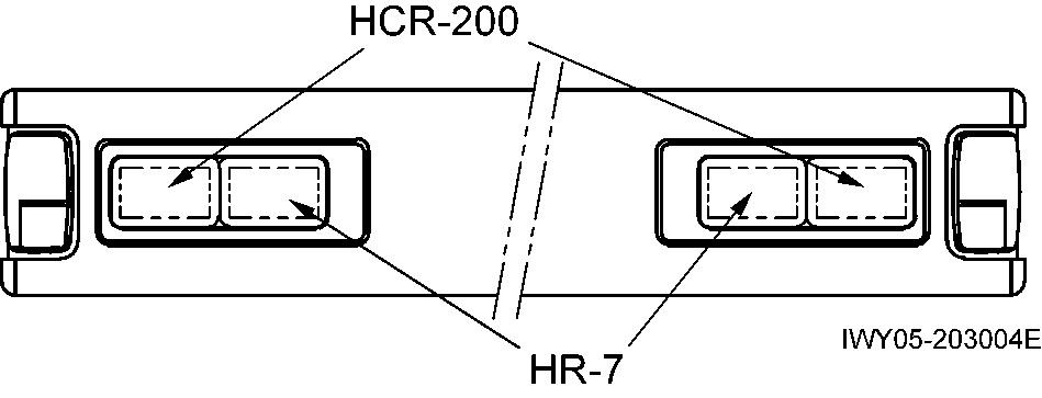
3. Adjust so that the maximum brightness is achieved at a position 1.9° D-2.2° L from the lamp center when measured by a tester.
1.9° ± 0.5° lower than horizontal
2.2° ± 0.5° to the left
4. Perform the above adjustment for both the left and right lamps.