11 minute read
Assembly Adjustment ( Traveling Device)

from Tadano Faun GR-250N-2 Rough Terrain Crane (Circuit Diagrams & Data) Service Manual SN FB4745 - PDF

8. Hydraulic suspension
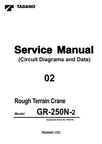
8.1 Releasing pressure in the accumulators for hydraulic suspension
When disassembling the components and pipings in the hydraulic suspension, release pressure in the accumulators beforehand in the method described below.
1. Perform vehicle height increasing operation of the crane in on-rubber operation configuration. After the suspension is extended to its stroke end, lock the suspension.
2. Extend the outrigger jacks to make the 4 wheels clear of the ground.
3. After setting the outrigger extension/retraction selector to the neutral, press the suspension free switch.
[NOTICE]
Before proceeding to the next step, wait at least 20 seconds after you press the switch.
4. Loosen the clasp of the hoses connected to the retraction port of each of 4 suspension cylinders carefully and slowly. If no pressure remains, you can remove the clasps. If pressure remains, repeat the step 3.
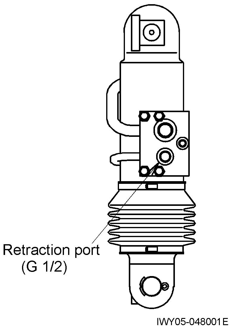
9. Retightening the hub nuts
・ Retighten the hub nut with the tightening torque of 640 ± 30 N•m {6500 ± 300 kgf•cm} (472±22ft lbf)
・ Retighten hub nuts after checking the brake force (See “6. Braking force”.), and before shipment. (The hub nuts must be settled before retightening. When the load is applied to the wheel mounting sections during braking force check, the nuts settle.)
・ Put the retightening torque for the hub nuts (the torque of the latest tightening) on the hub nut torque check record.
Operation Check (Crane Operation)
Y-8 Operation C h eck (Crane Operation)
1. Outrigger status indicator
Main switch : ON
Shift lever : Out of N position
2. Winch
1. Conditions Load : No load
Engine speed : Idling to medium speed
2. Pattern Move the telescoping lever all the way to the end of its stroke.
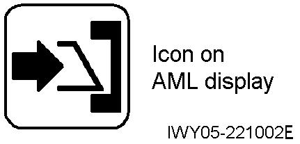
Operate the outrigger extension/retraction switch.
• With the auxiliary winch lever operated slightly, the main winch must move when it is operated with a partial lever stroke.
Icon flashes on the AML display.
Press the all outrigger control switch.
Outriggers do not move.
• When the auxiliary winch lever is moved to the end of its stroke, the main winch must not move even when its controls are operated.
3. Backward stability
1 Set the outrigger status on the AML to on-rubber status.
2 Raise the boom starting from this configuration, and check that the boom stops automatically when the boom angle reaches 80°.
3 Check that the boom lowering is available.
Main switch : ON
Shift lever : N position
4 Perform the above steps with the PTO ON.
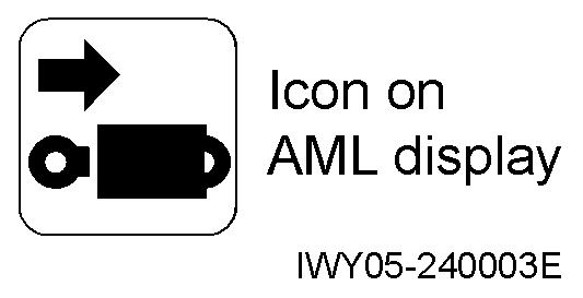
Operate the outrigger extension/retraction switch.
Icon flashes on the AML display.
Press the all outrigger control switch.
Outriggers move.
Operation Check (Crane Operation)
4. Jib side-up function
1. Automatic stop by overwind (two-blocking) must not occur while the jib set status is registered.
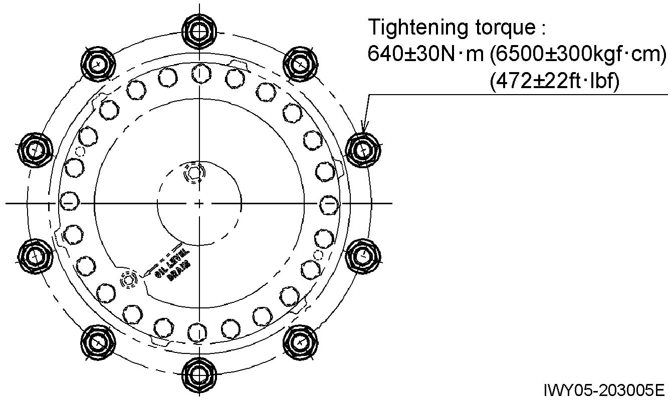
2. While the jib is mounted, check that the jib stowing (by retracting the cylinder) is not available when the jib connection pin is not inserted.
3. Check the jib lock icon (indicating that the jib lock pin is inserted).
• When the jib is secured on the bottom face of the boom, the icon shown below appears.
• After jib side-up stowing operation is completed, check that the symbol goes out.
4. Check that the jib raising (by extending the jib tilt cylinder) is not available when the jib lock pin is inserted.
5. Check that the jib raising (by extending the jib tilt cylinder) is not available when the jib lock pin is engaged.
6. Check the jib drop prevention function. Register the jib set status and perform the following check.
• While the jib lock pin is inserted and jib connection is not inserted (assuming the condition that the jib is swung from the bottom face of the boom to the front of the boom during jib mounting), check that you cannot extend the boom when the boom angle is less than 73°.
• While the jib lock pin and jib connection pin are inserted (assuming the condition that the jib is secured on the bottom face of the boom and going to be stowed by side-up), check that you cannot extend the boom when the boom angle exceeds 5°.
7. Checking indication of jib full retraction
• While the jib lock pin is not inserted (assuming the condition that the jib is suspended vertical toward the ground and going to be secured on the bottom face of the boom during jib stowing), the icon appears when the jib tilt cylinder is fully retracted.
• Check that the icon goes out when the jib tilt cylinder extends by 30 mm (1.2 in)
• After the check, always retract the jib tilt cylinder fully and stow the jib.
Operation Check (Crane Operation)
5. Warning [NOTICE]
For the location of the buzzers, refer to “Z-10 Electric Parts Location Diagram(Upper), 1. Inside cab”. Item Warning buzzer Sound Check conditions
AML limit Buzzer3 (CN818)
Overwind (Two-blocking) warning Buzzer4 (CN817)
Outrigger control switch detection
Buzzer1 (CN815,CN816)
• 280 Hz
• Continuous low tone
• 2300 Hz
• Continuous tremolo tones
• 2300 Hz
• Intermittent beeping
6. Eco mode operation check (FB6217--)
Occurs at moment of 100% when main switch is ON and PTO switch is ON. (Intermittent low tone sound occurs at moment of 90% and above.)
Occurs when the overwind (two-blocking) switch of either the main or auxiliary winch is turned ON by hoist-up operation.
Sounds when either the outrigger extension/retraction or jack slide selector switch has been left in any position other than neutral 10 seconds after operation is completed.
While the PTO is engaged, select the Eco mode 1 and Eco mode 2, and depress the accelerator pedal fully. Then check that the maximum engine speed lowers while the respective mode is selected.
Eco mode Max. engine speed (min-1)
Approx. 1,900
Approx. 1,550
Approx. 1,350
Use the AML to select the Eco mode 1 or Eco mode 2. The maximum engine speeds above listed are for reference.
Operation Check (Traveling Device)
Y-9 Operation Check (Traveling Device)
1. Exhaust brake (EXB)
1. Turn on the EXB brake, and keep the engine idling. (The pilot lamp remains lit.)
2. Check pattern
Seq. EXB
1
Release the accelerator pedal. With the shift lever in the N position, turn the EXB switch ON. (The pilot lamp illuminates.) OFF
2 Move the shift lever from the N position to the D position. Increase the vehicle speed to 1 km/h (0.6214 MPH) or above. ON
3 Depress the accelerator pedal. OFF
4 Release the accelerator pedal. ON
5 Use the service brake to reduce the vehicle speed to 1 km/h (0.6214 MPH) or less. OFF
6 Release the brake pedal and increase the vehicle speed to 1 km/h (0.6214 MPH) or above. ON
7 Move the shift lever to the N position. OFF
[NOTICE]
Check whether EXB is operating or not from the engine noise and from the movement of the air cylinder.
2. Retarder
1. After jacking up the vehicle and setting the drive mode to 4WD, turn ON the retarder switch (by setting the lever in the Hi or Low position). (The pilot lamp illuminates.)
2. Move the shift lever out of N into D, and depress the accelerator pedal.
→When the accelerator pedal is released, the retarder works.
→When the accelerator pedal is depressed again, the retarder stops working.
(Check the operation sound of the valve to judge whether the retarder is working.)
3. Accelerator OFF
→When the vehicle speed is lower than 1 km/h (0.6214 MPH), the retarder does not work.
Operation Check (Traveling Device)
3. Automatic transmission [NOTICE]
Numerals indicate speedometer readings
( ) Indicates lock-up ON/OFF point.
Indicates downshift points when the accelerator position is 90% or above. (These do not need to be checked.)
(★) Indicates the lock-up OFF point when the accelerator position is 90% or above. (These do not need to be checked.)
4. Rear steering lock
4.1 Operation check A
Operation Check (Traveling Device)
Turn the rear steering lock switch to "Release". (The lamp turns on.)
Lamp is on. Lamp is off.
Check that the lamp is on.
Switch to 4-wheel, crab, or rear steering.
Switch to 4-wheel, crab, or rear steering.
2-wheel steering lamp remains on and the 4-wheel, crab, or rear steering lamp flashes.
Check that the lamp is on. (4-wheel, crab, or rear steering)
With the steering release switch pressed, slowly turn the steering wheel left and right.
Check that the lamps are ON.
Turn the steering wheel and check the steering.
After checking that the lamp turns off and on, turn the steering wheel to a position where the lamp is on.
Turn the rear steering lock switch to "Lock".
If the pin does not engage, adjust the position of the detector cam so that the detector switch activates when the pin can be inserted.
Check that the lamps are OFF.
4-wheel, crab or rear steering lamp flashes. Switch to 2-wheel steering, and check that 2-wheel steering lamp turns on and the 4-wheel, crab, or rear steering lamp turns off.
IWY05-0141E16
Operation Check (Traveling Device)
4.2 Operation check B
1. With the lock pin engaged, upshift to 3rd gear. Check that the lock pin does not disengage even when the rear steering lock switch is turned to "Release".
2. Upshift to 4th gear. Check the same details as in step 1.
3. Downshift to 2nd gear. Turn the rear steering lock switch to "Release". Check that the lock pin disengages (indicator lamp turns on).
5. Overshift prevention [NOTICE]
Jack up the vehicle and shift to 4WD High position. Perform the operations below and check the shift position with the combination meter.
Perform both in economy mode and power mode.
1. Move the shift lever to “D” and increase speed to 40 km/h or more. Check that transmission shifts to 4th gear (display: D).
2. Gradually reduce speed. Maintain a speed of 38 km/h. Move the shift lever to “3”. Check that transmission does not downshift (display: D).
3. Gradually reduce speed. Check that transmission downshifts to 3rd gear when the speed is 35 km/h (display: 3).
4. Downshift to 1st gear. Check the same details as in step 3.
5. With the lock pin disengaged, check that the vehicle does not upshift to 3rd gear.
4. Reduce speed. Maintain a speed of 26 km/h. Move the shift lever to “2”. Check that transmission does not downshift (display: 3).
5. Gradually reduce speed. Check that transmission downshifts to 2nd gear at 23 km/h (display: 2).
6. Reduce speed. Maintain a speed of 14 km/h. Move the shift lever to “1”. Check that transmission does not downshift (display: 2).
7. Gradually reduce speed. Check that transmission downshifts to 1st gear at 11 km/h (display: 1).
Meter speed Combination meter display a 40 km/h (24.9 MPH) D b 38 km/h (23.6 MPH) D c 35 km/h (21.7 MPH) 3 d 26 km/h (16.2 MPH) 3 e 23 km/h (14.3 MPH) 2 f 14 km/h (8.7MPH) 2 g 11 km/h (6.8 MPH) 1
Operation Check (Traveling Device)
6. Warning [NOTICE]
For the location of the buzzers, refer to “Z-10 Electric Parts Location Diagram(Upper), 1. Inside cab”. (I km/h = 0.6214 MPH) Item
1. Air pressure is 540 kPa {5.5 kgf/cm2} (78.3 psi) or less. With the parking brake switch OFF, the main switch is turned ON.
Low air pressure and parking brake
Buzzer1 (CN815,CN816)
• 2300 Hz
• Continuous beep
2. The parking brake and the brake lock are applied, the shift lever is in D, and the vehicle speed is 1 km/h or less.
→The buzzer does not sound if any of the above condition is met. It sounds in all other cases.
Engine overrun Buzzer1 (CN815,CN816)
• 2300 Hz
• Intermittent beeping
The mechanism sounds at engine speed of 3130 min-1 There is not need to check it.
Turns OFF at 2910 min-1
Attach a step-up gear to the vehicle speed detection gearbox.
Speed warning Buzzer1 (CN815,CN816)
• 2300 Hz
• Continuous and intermittent sound
Accelerating Intermittent sound at 59 km/h on speedometer reading
Continuous sound at 62 km/h on speedometer reading
Decelerating Intermittent sound at 60 km/h on speedometer reading
OFF at 54 km/h on speedometer reading
Low torque converter oil pressure
Buzzer1 (CN815,CN816)
7. Speedometer
• 2300 Hz
• Continuous beep
While the parking brake is released, the buzzer sounds when the torque converter pressure is 1 MPa {10 kgf/cm2} (145 psi) or less.
(I km/h = 0.6214 MPH)
When the actual traveling speed of the vehicle is V2, the reading of the speedometer (V1) shall meet the following formula:
0 V1 -V2 V2 / 10 + 6
Ex. Case of a vehicle of [45km/h < Vmax 55km/h]
When the speedometer reading is 40 km/h, V1 becomes 40 km/h.
Thus the tester speed V2 shall be as follows:
30.91 km/h V2 40 km/h
Operation Check (Traveling Device)
8. Hydraulic suspension
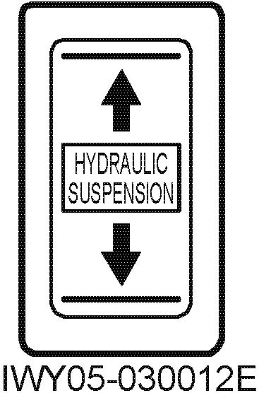
8.1
Turn ON the main switch to start engine.
↓
Keep pressing the suspension free switch for 1 second or more.
Check that the suspension emergency free switch is on the normal position and put the vehicle into a traveling state.
Flashes during leveling (0.8 second interval) Goes out after leveling
Free after leveling (Normal traveling state)
Leveling is impossible when the road surface is not flat. In this case, adjust to the lock state by operating the UP/DOWN switch, move to a flat ground, and then operate the suspension free switch again.
Locked after vehicle height is raised
Locked after vehicle height is lowered
Vehicle height is raised or lowered while the switch is being pressed. The vehicle height is locked when the operation switch is pressed.
↓
Keep pressing the suspension free switch for 1 second or more.
Flashes during leveling (0.8 second interval). Goes out after leveling.
Free after leveling (Normal traveling state.)
Free

(Normal
Keep pressing the suspension free switch for 1 second or more.
↓
Operation Check (Traveling Device)
Swing the boom in an over-side direction.
Check that the suspension does not fall even if the UP/DOWN switch or suspension free switch is pressed while the boom is in an over-side.
After swinging the boom to the over-front, stow the jacks and slides.
Keep pressing the suspension free switch for 1 second or more.
Turn OFF the main switch to stop engine.
Flashes during leveling (0.8 second interval). Goes out after leveling.
Free after leveling (Normal traveling state)
Next time the main switch is turned ON and the engine is started, the suspension state before the engine is stopped will be resumed.
Operation Check (Traveling Device)
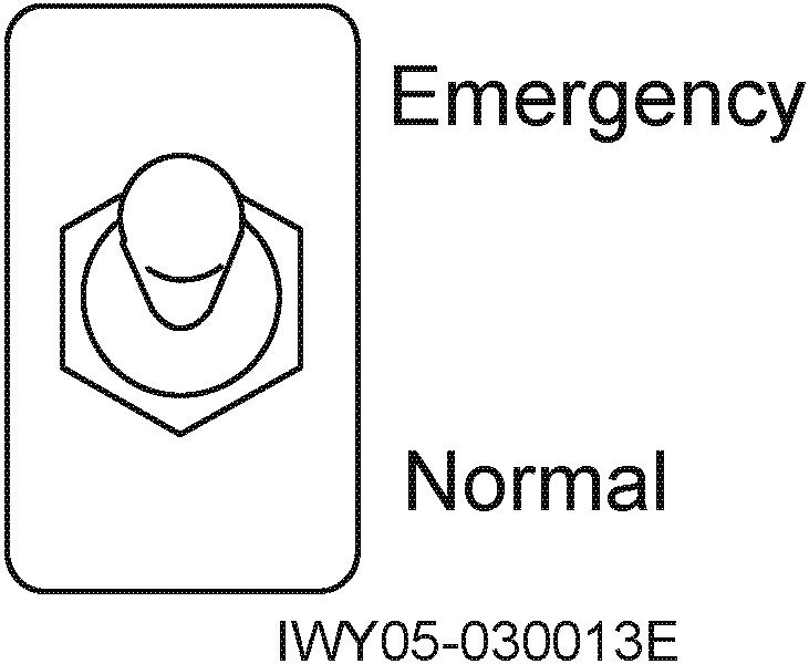
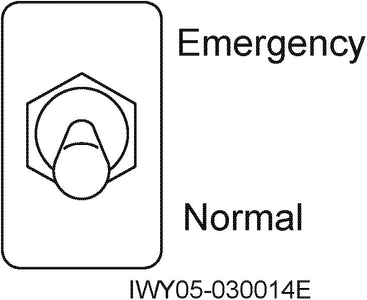
8.2 Check pattern for emergency operation
Turn ON the main switch to start engine.
↓ Keep pressing the suspension free switch for 1 second or more.
UP/DOWN switch
Suspension emergency free switch
Keep pressing the suspension free switch for 1 second or more.
Keep pressing the suspension free switch for 1 second or more.
Extend the slides by the outrigger operation switch (central/individual) and jack up the crane.
Check that the suspension emergency free switch is on the normal position, and put the vehicle into a traveling state. Flashes during leveling (0.8 second interval). Goes out after leveling.
Free after leveling (Normal traveling state)
Leveling is impossible when the road surface is not flat. In this case, adjust to the lock state by operating the UP/DOWN switch, move to a flat ground, and then operate the suspension free switch again.
Press the UP/DOWN switch for a moment to put into a suspension lock state.
Shift the suspension emergency free switch to Emergency. Lights up Locked
Flashes (0.4 second interval) Suspension emergency free
Check that suspension up and down operations cannot be performed.
Flashes (0.4 second interval) Suspension emergency free
Operation Check (Traveling Device)
Swing the boom in an over-side direction.
Lights up
OFF Lights up
↓ PTO
ON Lights up
Locked ↓
Keep pressing the suspension free switch for 1 second or more.
↓
Perform boom extending operation.
↓
Perform boom raising operation.
↓
Set the crane in the traveling state by the telescoping, elevating and swing operation, then turn OFF the PTO (with the suspension as is).
Flashes (0.4 second interval) Suspension emergency free
Locked ↓
Keep pressing the suspension free switch for 1 second or more.
↓
Locked ↓
↓
Operation Check (Traveling Device)
Flashes
(0.4 second interval)
Flashes during leveling (0.8 second interval). Goes out after leveling.
Inspection and Maintenance
Y- 10 Inspection and Maintenance
1. Refer to “Inspection and Maintenance” in “Operation Manual” of its applicable crane.
2. Maintenance of Line Filter
[NOTE] For the location of the parts, see "Z-1.1 Comparison table of hydraulic parts (No., part name and location)", "Z-6 Hydraulic parts location diagram (upper)", and "Z-7 Hydraulic parts location diagram (lower)" in the chapter Z.
Boom Connecting Pin and Thread Side Table
Y- 11
Boom Connecting Pin and Thread Size Table
Note: “ ” means that more than one spec. No. are applicable.