7 minute read
Air Bleeding Procedure

from Tadano Faun GR-250N-2 Rough Terrain Crane (Circuit Diagrams & Data) Service Manual SN FB4745 - PDF

FB6315--
Bleed this valve after the pilot circuits (hydraulic pilot control valves) (See the section 2.4.) and the positive control circuit (See the section 2.6.) are bled.
Conditions
Engine speed: idling PTO: ON
1. Open the air-bleed plug and move the winch lever fully to the end of its stroke in the direction corresponding to the plug.
2. When there are no more bubbles in the oil that flows out, tighten the plug while lever operation is continued.
Then bleeding of the valve section is completed.
--FB6314
Adjusting Procedure (Electric)
Y-5 Adjusting Procedure (Electric)
1. Switch adjustment procedure
1.1 Over-front detection proximity switch (CN521)
1. Apply thread locking agent (ThreeBond 1401 or equivalent) to the threaded section of the switch beforehand.
2. Swing the boom to the over-front and set the boom angle 60° or higher.
3. Adjust the vertical position of the switch, and fix the switch using a nut. Nut tightening torque: 19 - 20 N·m {193 - 204 kgf·cm} (14 - 14.8 ft·lbf)
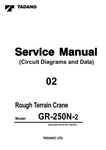
1.2 Boom full retraction detection switch (CN552)
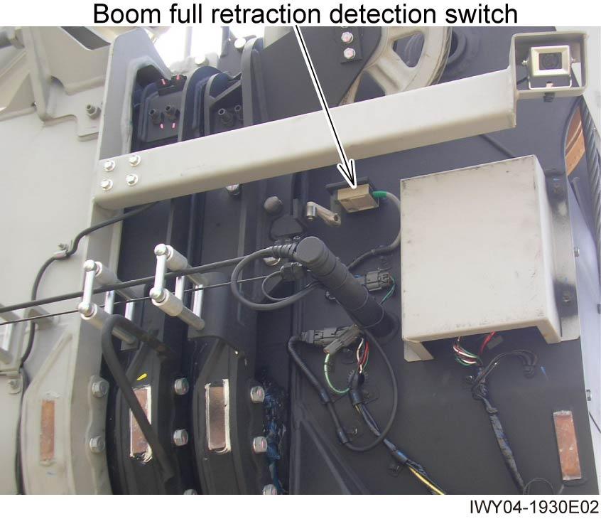
Adjust the switch position so that its contact is closed when the top boom section is retracted to the position where it is 5 to 8 mm (0.2 to 0.31 in.) longer than its fully retracted length. Switch fixing bolt tightening torque:
4.9 - 5.9 N m {50 - 60 kgf cm} (3.6 - 4.4 ft lbf)

Adjusting Procedure (Electric)
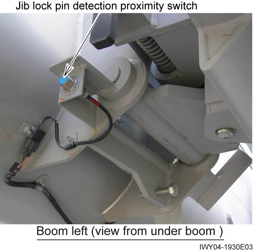
1.3 Jib lock pin detection proximity switch (CN573)
1. Apply thread locking agent (ThreeBond 1401 or equivalent) to the threaded section of the switch.
2. Swing the jib from the side of the boom, and secure it on the bottom face of the boom (by securing it by the jib lock mechanism).
3. Adjust the horizontal position of the switch so that the clearance A is 4 mm (0.16 in), and fix the switch using a nut.
4. Make sure that the green LED( FB6560) or red LED(FB6561 ) lights up when the switch is activated.
Nut tightening torque: 40 - 50 N·m {410-510kgf·cm} (29.5 - 36.8 ft·lbf)
1.4 Jib connection pin detection switch (CN572)
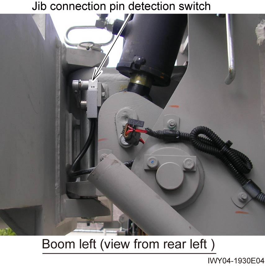
1. Apply thread locking agent (ThreeBond 1401 or equivalent) to the threaded section of the switch fixing bolt.
2. Swing the jib from the side of the boom, and secure it on the bottom face of the boom (by securing it by the jib lock mechanism).
3. Adjust the lever angle so that the switch contact is closed when the lever is at the position A shown in the figure. Switch fixing bolt tightening torque: 4.9 - 5.9 N·m {50 - 60 kgf·cm} (3.6 - 4.4 ft·lbf)
IWY04-058105

Adjusting Procedure (Electric)
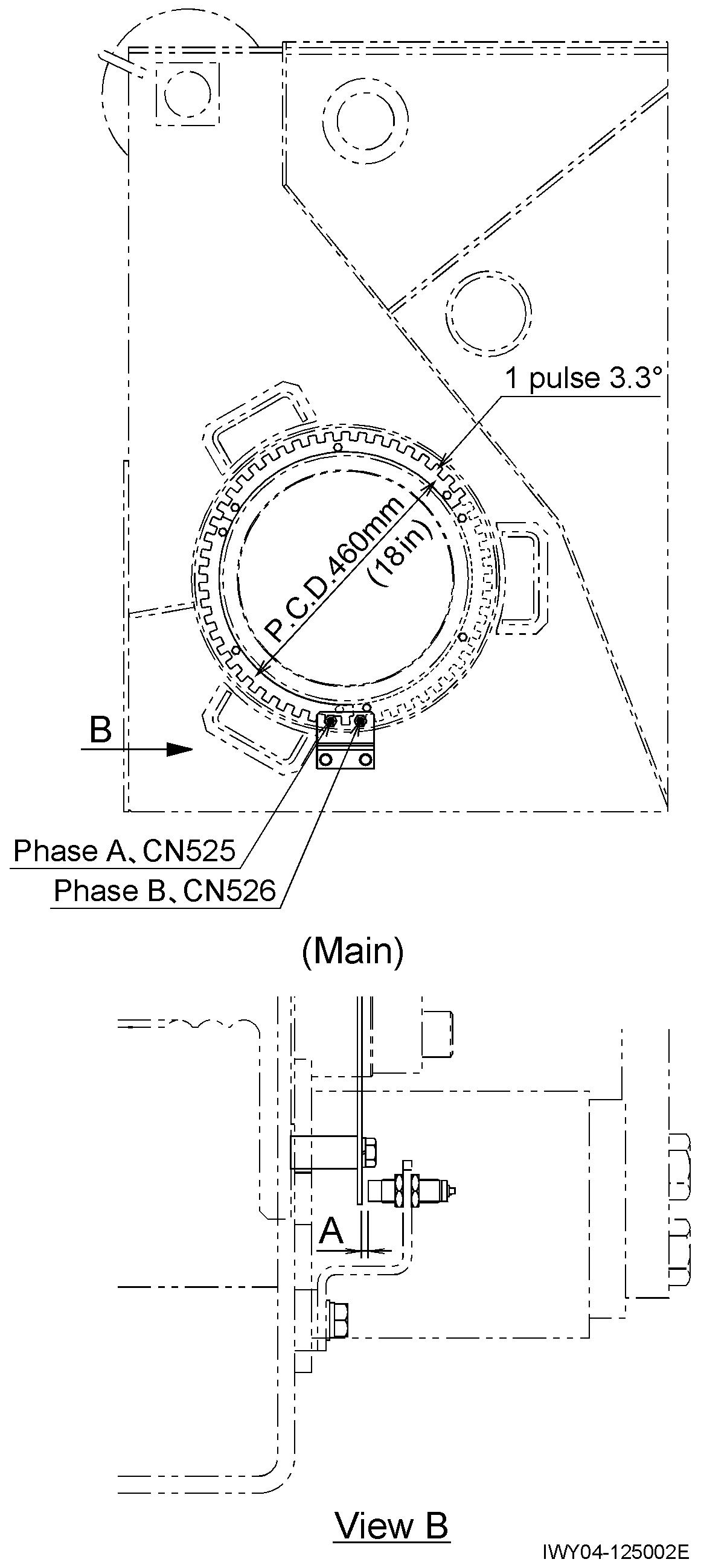
1.5 Main wire rope length detection (Phase A: CN525) (Phase B: CN526)
1. Apply thread locking agent (ThreeBond 1401 or equivalent) to the threaded section of the switch beforehand.
2. Adjust the horizontal position of the switch so that the clearance A is 3.5 mm (0.14 in), and fix the switch using a nut. Nut tightening torque: 19 - 20 N m {193 - 204 kgf cm} (14 - 14.8 ft lbf)
3. Make sure that the green LED lights up when the switch is activated.
1.6 Aux. wire rope length detection (Phase A: CN527) (Phase B: CN528)
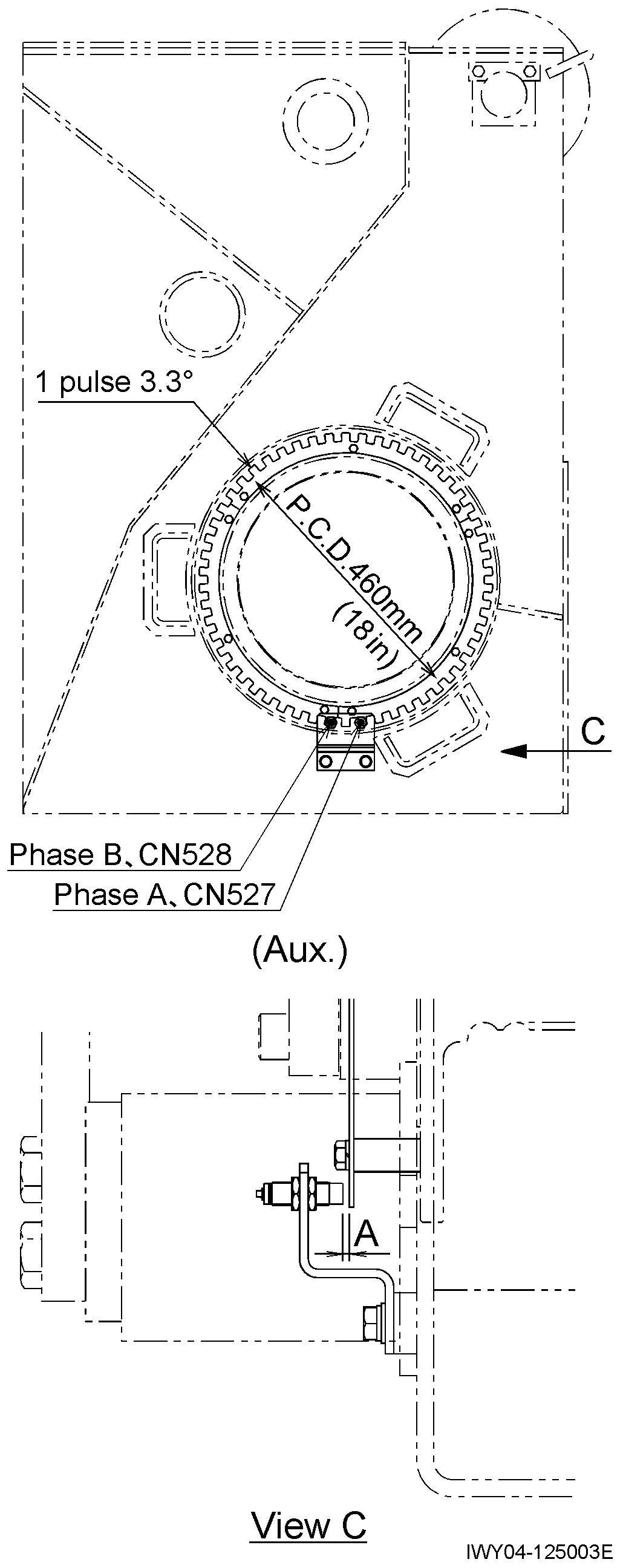
1. Apply thread locking agent (ThreeBond 1401 or equivalent) to the threaded section of the switch beforehand.
2. Adjust the horizontal position of the switch so that the clearance A is 3.5 mm (0.14 in), and fix the switch using a nut. Nut tightening torque: 19 - 20 N m {193 - 204 kgf cm} (14 - 14.8 ft lbf)
3. Make sure that the green LED lights up when the switch is activated.
Adjusting Procedure (Electric)
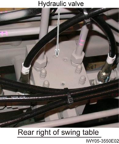
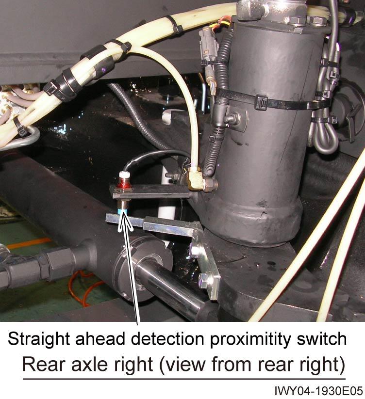
1.7 Straight ahead detection proximity switch (CN408)
1. Apply thread locking agent (ThreeBond 1401 or equivalent) to the threaded section of the switch beforehand.
2. Steer the rear wheels so that they face straight ahead.
3. Adjust the vertical position of the switch so that the clearance A is 3 mm (0.12 in), and fix the switch using a nut. Nut tightening torque: 19 - 20 N m {193 - 204 kgf cm} (14 - 14.8 ft lbf)
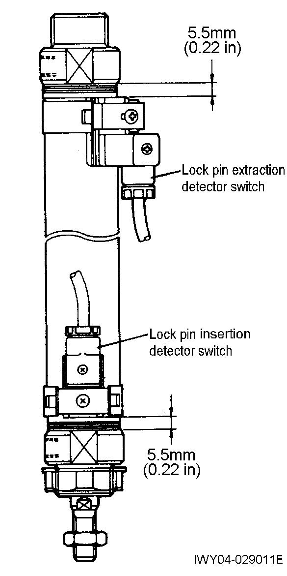
1.8 Rear steering lock pin insertion detection switch (CN417)
1.9 Rear steering lock pin extraction detection switch (CN418)
Adjust the vertical position of the lock pin insertion detector switch and lock pin extension detector switch. Then fix the switches. Switch fixing screw tightening torque: 0.49 - 0.68 N·m {5 - 7 kgf·cm} (0.34 - 0.5 ft·lbf)
Adjusting Procedure (Electric)
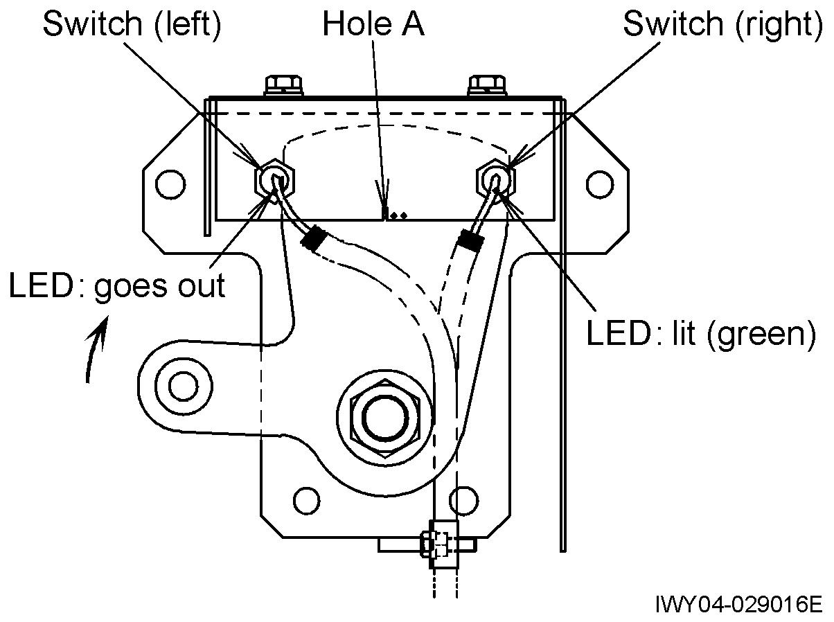
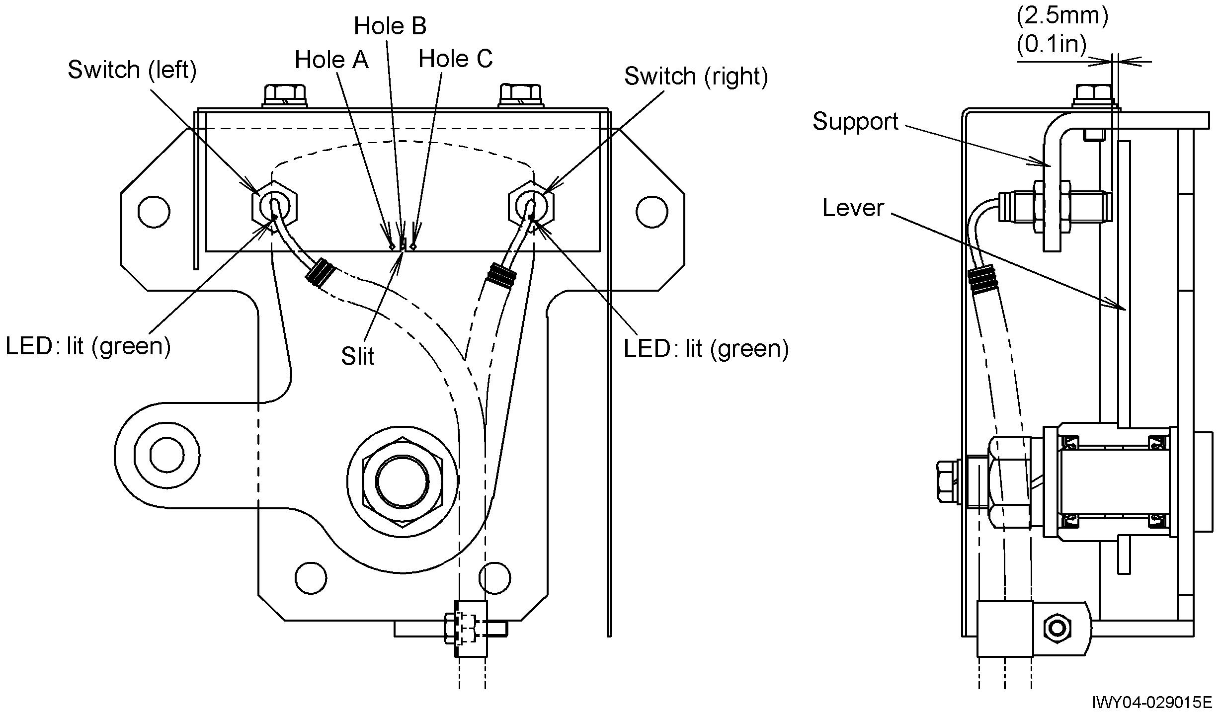
1.10 Vehicle height detection FL(L) (CN400), FL(R) (CN401)
1.11 Vehicle height detection RR(L) (CN406), RR(R) (CN407)
1. Apply thread locking agent (ThreeBond 1401 or equivalent) to the threaded sections of the right and left switches beforehand.
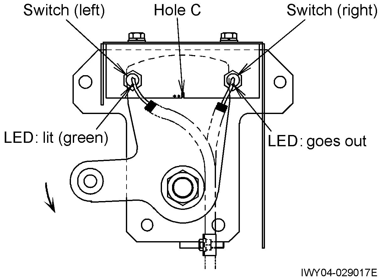
2. Adjusting the left switch
Adjust the clearance between the detection face of the left switch and the lever so that the LED of the left switch turns from lighting in green into going out when the lever is turned clockwise until its hole A is aligned with the slot in the support. And fix the switch with a nut.
Nut tightening torque:
19 - 20 N m {193 - 204 kgf cm} (14 - 14.8 ft lbf)
3. Adjusting the right switch
Adjust the clearance between the detection face of the right switch and the lever so that the LED of the right switch turns from lighting in green into going out when the lever is turned counterclockwise until its hole C is aligned with the slot in the support. And fix the switch with a nut.


Nut tightening torque:
19 - 20 N·m {193 - 204 kgf·cm} (14 - 14.8 ft·lbf)
4. Align the hole B in the lever with the slot of the support, and check that the LEDs on the right switch and left switch are lit in green.
2 347-904-35000
Adjusting Procedure (Elec trical)
1.12 Vehicle height detection FR(L) (CN402), FR(R) (CN403)
1.13 Vehicle height detection RL(L) (CN404), RL(R) (CN405)
Apply thread locking agent (ThreeBond 1401 or equivalent) to the threaded sections of the right and left switches beforehand.
2. Adjusting the left switch
Adjust the clearance between the detection face of the left switch and the lever so that the LED of the left switch turns from lighting in green into going out when the lever is turned clockwise until its hole A is aligned with the slot in the support. And fix the switch with a nut.
Nut tightening torque:
19 - 20 N·m {193 - 204 kgf·cm} (14 - 14.8 ft·lbf)
3. Adjusting the right switch
Adjust the clearance between the detection face of the right switch and the lever so that the LED of the right switch turns from lighting in green into going out when the lever is turned counterclockwise until its hole C is aligned with the slot in the support. And fix the switch with a nut.
Nut tightening torque: 19 - 20 N m {193 - 204 kgf cm} (14 - 14.8 ft lbf)
4. Align the hole B in the lever with the slot of the support, and check that the LEDs on the right switch and left switch are lit in green.
347-904-36000
Assembly Adjustment (Crane Operation)
Y-6 Assembly Adjustment (Crane Operation)
1. Adjusting boom telescoping wire rope
1.1 Adjusting the telescoping wire rope for the top and 3rd boom sections
1. With the boom fully retracted, tighten adjustment nut A for the top boom section retraction wire rope to apply tension to the wire rope.
2. Evenly tighten the adjustment nuts B (4 points) at the threaded end of the 3rd boom section extension wire rope, so that the 3rd boom section is slightly (1 - 5 mm (0.04 - 0.2 in)) away from the 2nd boom section.
Assembly Adjustment (Crane Operation)
3. Evenly tighten the adjustment nuts C (2 points) at the threaded end of the top boom section extension wire rope until the top boom section is slightly (1 - 5 mm (0.04 - 0.2 in)) away from the 3rd boom section.
4. Tighten adjustment nut A of the top boom section retraction wire rope until the top and 3rd boom sections are blocked by their respective stoppers (the boom sections are fully retracted).
5. Extend the boom by 200 to 300 mm {0.656 to 0.984 ft.}, then retract it all the way to complete adjustment. If the boom is not fully retracted, follow the below procedure to check and adjust it.
Check the tension of the 3rd boom section extension wire rope.
Slack Tense
Tighten adjustment nuts B (4 points) at the threaded end of the 3rd boom section extension wire rope by approx. 1/3 turn.
Loosen adjustment nut A of the adjuster for the top boom section retraction wire rope by approx. 1/3 turn.
Extend and fully retract the boom to check.
Extend and fully retract the boom to check.
Only the 3rd boom section extends.
Evenly tighten the right and left adjustment nuts C (2 points) at the threaded end of the top boom section extension wire rope by approx. 1/3 turn each.
Extend and fully retract the boom to check. End
Assembly Adjustment (Crane Operation)
2. Bubble level adjustment
The upper bubble level in the cab and the lower bubble level on the outrigger control panel must be adjusted so that they are parallel to the swing table plane (*1). The following shows the general adjustment procedure for bubble levels of large cranes (AC, RC and TC cranes). (*2)
2.1 Leveling the swing table plane
First set the machine so that the swing table plane is horizontal. Prepare bubble levels other than the ones provided with the machine and set the machine in either of the methods A and B.
Conditions
Location: On firm and level ground
Outrigger configuration: Maximum extension
Boom configuration: Fully retracted; at elevation angle of 50°; no load on the hook block
○Method A (Case where the machining surface on the swing bearing can be used)
In case that the machining surface on the swing bearing is exposed from the base plate of the swing table, place bubble levels directly on the machining surface on the swing bearing with the boom directed to over-front. (See Fig. 2.) Then extend the jacks to set the machine level in lateral and longitudinal directions. (*3)
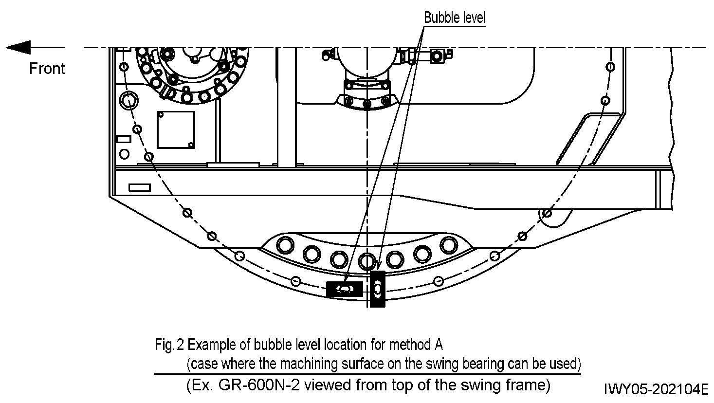
After leveling the machine, make sure that the jack floats are not shaky.