3 minute read
Assembly Adjustment (Crane Operation)

from Tadano Faun GR-250N-2 Rough Terrain Crane (Circuit Diagrams & Data) Service Manual SN FB4745 - PDF

○Method B (Case where the machining surface on the swing bearing cannot be used)
1. If the machining surface on the swing bearing is not exposed, place bubble levels on the base plate on the swing table with the boom directed to over-front. Then extend the jacks to set the machine level in lateral and longitudinal directions. (*3) After leveling the machine, make sure that the jack floats are not shaky.
2. In this condition, swing the boom by 360° and check the movement of bubbles in the levels. If the swing table plane is level, bubbles hardly move during swing of the boom. If the bubbles move during swing of the boom, estimate the inclination of the swing table plane from the movement of the bubbles and operate the jacks for fine adjustments.
3. Repeat the above-mentioned check and fine adjustments until the bubbles in the levels hardly move during swing of the boom. After final fine adjustment, reset the bubble levels (*4) and swing the boom by 360° again to check the movement of the bubbles.
*1: "Swing table plane" refers to the virtual surface on which the upper structure of the crane swings. In mechanical structure, it corresponds to the machining surface on the swing bearing.
*2: Apply this procedure when readjusting.
*3: Level the machine by extending the jacks. If jacks are retracted for adjustment, the jack floats may become clear of the ground.
*4: If the place where bubble levels are placed is not parallel to the swing table plane when performing the method B, resettable bubble levels are required.
Assembly Adjustment (Crane Operation)
2.2 Upper and lower bubble level adjustment
After leveling the swing table plane, adjust so that the bubble in each upper and lower bubble level is center-aligned to the mark using the adjuster screw of each bubble level with the boom directed to over-front and boom angle of 50°.
2.3 Adjustment check
Finally check if the grade 3 of the TIS's "Inspection standard of bubble levels' bubble position" is satisfied.
Conditions: Outriggers at full extension; boom fully retracted and no load on the hook block.
・Standard for the upper bubble level (grade 3): Swing the boom with the boom angle of 50°. Check that the bubbles are within the marked range when the boom is directed to front, rear, right and left.
・Standard for the lower bubble level (grade 3): While the boom is directed to over-front and stowed, check that each bubble is within the marked range.
2.4 Readjustment
If the standard for grade 3 is not satisfied, check whether the jacks are shaky and make adjustment again.
Y-7 Assembly Adjustment ( Traveling Device)
1. Service brake adjustment
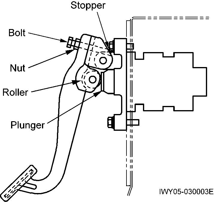
1.1 Brake pedal adjustment
With the roller contacted with the plunger due to the weight of the brake pedal, tighten the bolt until it touches the stopper and lock it with the nut.
1.3 Check after replacing brake hose
After you replace the brake hoses and so on, make sure that any contact does not occur between the hoses and the structures in any situation. Check it with moving suspension (up and down) and steering (right and left.) In addition, make sure that any hose is not twisted forcibly.

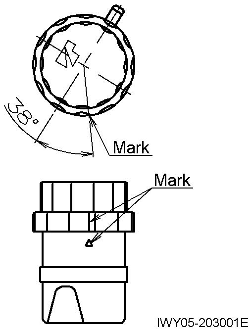
1.2 Tightening the cap of reserve tank of service brake fluid
[NOTICE]
Tightening the cap excessively may break the stopper.
1. Tighten the cap until it stops at the stopper.
2. Check that the position of the tank body and cap is as shown in the figure below.
Assembly Adjustment ( Traveling Device)
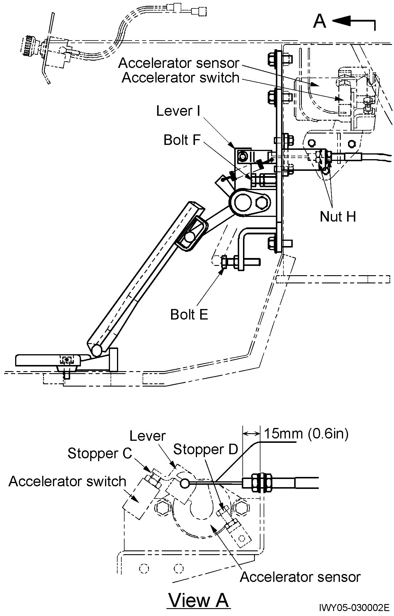
2. Accelerator adjustment
2.1 Accelerator pedal adjustment
1. Adjust bolt F so that lever I is vertical, then lock the bolt with the nut.
2. Move the accelerator sensor lever so that it contacts stopper C. Then adjust nut H until there is no pedal play.
[NOTICE]
Be sure to check that the accelerator switch (idle SW) operates reliably.
3. When the pedal is fully depressed (accelerator sensor lever in contact with stopper D), place bolt E in contact with the lever on the underside of the pedal, and lock it in place with the nut.
2.2 Engine speed
[NOTICE]
Before checking the engine speed, run the engine to warm it up. (Temperature of the torque converter oil should reach approx. 50°C (122°F).)
1. No-load Max. speed
• PTO OFF : 2860 ± 50 min-1
• PTO ON : 1900 min-1 (Eco mode : OFF)
• Speed limiter ON : 2460 min-1
2. Idling speed
・With PTO OFF 600 ±20 min-1 (with PTO OFF and A/C OFF)
・With PTO ON 670 ± 20 min-1 (With PTO ON and A/C ON)
2.3 Procedure for checking engine stall speed
If engine output power decreases or torque converter oil is heated significantly, check the engine stall speed as follows:
Caution
When the engine is stalled, heat is generated inside the torque converter. Therefore, never run the engine for 30 seconds or longer, and never run the engine if the oil temperature is 90°C (194°F) or above.
The torque converter generates maximum torque at this time. Therefore, be careful to avoid sudden movement of the vehicle.
1. Set the switches and controls as described below.
• PTO switch : OFF
• Shift lever : 3rd gear
• Drive mode selection switch : 4WD - High
• Service brake : Applied
2. While depressing the brake pedal, depress the accelerator pedal all the way. Check the engine speed.
Max. speed standard when stalled: Approx. 2050 min-1