19 minute read
Functions of and How to Us e User Mode (TL-300E-3)


How to Use the Working Range Limit Function
[NOTICE]
If the working range limit is registered very close to an obstacle, there is a risk of the crane colliding with the obstacle, depending on the operational status and the manner in which the load is handled. When registering a range limit, allow a sufficient clearance to avoid collision.
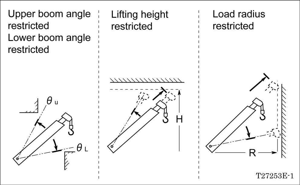
The working range restricting function makes the boom automatically stop at the previously registered boom angles (upper and lower), lifting height and load radius.
The function is useful for handling a load in a confined place because it defines the area in which the boom can operate.
[NOTICE]
Turning the power off (PTO switch: OFF) automatically erases all the previous settings stored in memory after approximately 2 hours. To resume the operation more than 2 hours after the power has been last turned off, enter the settings all over again.
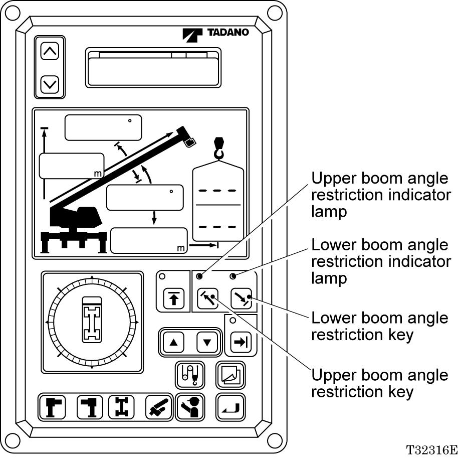
Boom Angle Limit
Raise or lower the boom to the desired angle, and press the boom upper or lower angle restriction key. The corresponding restriction indicator lamp will flash, indicating that the boom angle limit has been registered in the memory. When the boom is moved back to an angle within the set limit, the restriction indicator lamp stops flashing and stays illuminated.
Thereafter, the upper or lower boom angle restriction indicator lamp flashes and the AML buzzer sounds for 3 seconds whenever the upper or lower limit previously registered is reached. (Boom raising or lowering stops automatically.) To cancel the boom angle limit function, press the boom angle restriction key again. The corresponding boom angle restriction indicator lamp will go out.
Functions of and How to Us e User Mode (TL-300E-3)
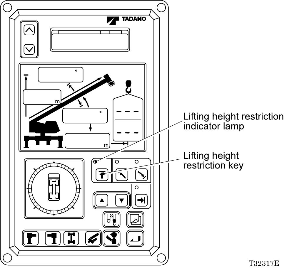
Lifting Height Limit
Move the boom to the desired height, and press the lifting height restriction key. The lifting height restriction indicator lamp will flash, indicating that the height limit has been registered in the memory. When the boom is moved back to a height within the set limit, the lifting height restriction indicator lamp stops flashing and stays illuminated. Thereafter, the lifting height restriction indicator lamp flashes and the AML buzzer sounds for 3 seconds whenever the height limit previously registered is reached. (Boom raising and extending stop automatically.)
To cancel the height limit function, press the lifting height restriction key again. The lifting height restriction indicator lamp will go out.
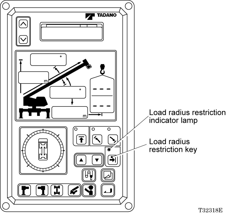
Load Radius Limit
Move the boom to the desired load radius, and press the load radius restriction key. The load radius restriction indicator lamp will flash, indicating that the load radius limit has been registered in the memory. When the boom is moved to a radius within the set limit, the load radius restriction indicator lamp stops flashing and stays illuminated. Thereafter, the load radius restriction indicator lamp flashes and the AML buzzer sounds for 3 seconds whenever the limit previously registered is reached. (Boom extending and lowering stop automatically.)
To cancel the load radius limit function, press the load radius restriction key again. The load radius restriction indicator lamp will go out.
Functions of and How to Us e User Mode (TL-300E-3)
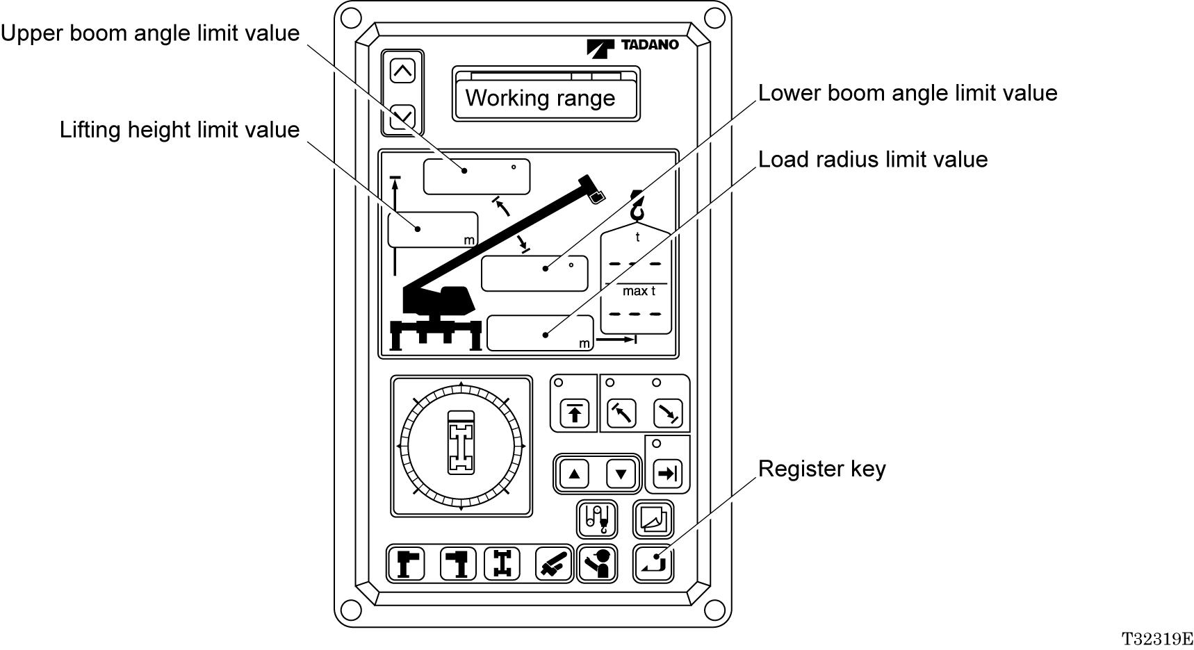
Display of Working Range Limit Values
Press the register key while working range limits have been registered. While the key is being pressed, the registered working range limit values are displayed. On the moment display will be displayed a message "Working range".
[NOTICE]
This display is not made during a preoperational check of the AML and when a working state is being registered.
When working range limits are not registered, the message " " will be displayed.
Functions of and How to Us e User Mode (TL-300E-3)
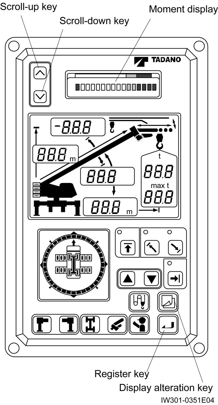
Display Alteration
Displays on the moment display and the display panel 1 can be altered, as shown below in the figures, by pressing the display alteration key. The indicative symbols are displayed, too.
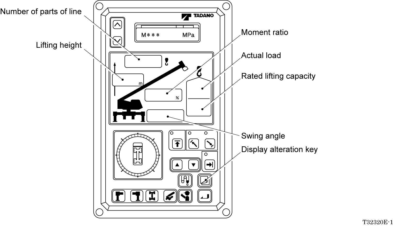
Displays on the actual load display and the rated load display do not alter even when the display alteration key is pressed.
General: Adjustment M ode and Maintenance Mode
[ADJUSTMENT AND MAINTENANCE]
General: Adjustment M ode and Maintenance Mode
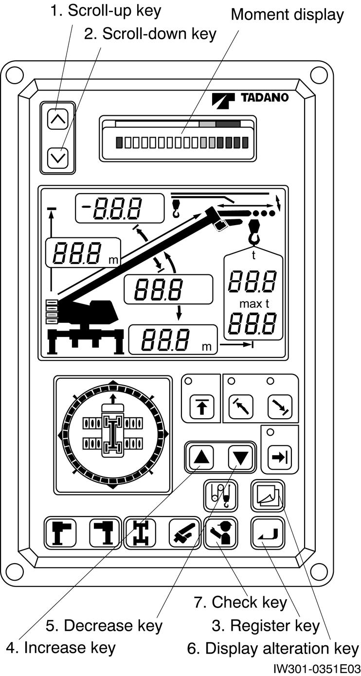
1. Keys and Switches for Adjustment and Maintenance
1. Scroll-up key
Used to see the previous lines of message displayed on the moment display.
2. Scroll-down key
Used to see the next lines of messages displayed on the moment display.
3. Register key
Used to register the selected state and write the adjustment value in EEPROM.
4. Increase key
Used to increase the adjustment value.
5. Decrease key Used to decrease the adjustment value.
6. Display alteration key
Used to change the display to the upper menu.
8. Moment input short-circuit switch Top view
9. Protect switch
10. Moment zero adjuster
11. Abnormality display LED
IW301-0131E02
7. Check key
Used for îDo Checkî and îAo Checkî functions in the maintenance mode.
8. Moment input short-circuit switch
Not used for this machine.
9. Protect switch
Set this switch to OFF when changing the mode from user mode to adjustment mode. With this switch OFF, data in the EEPROM becomes rewritable.
10.Moment zero adjuster
This adjuster is for adjustment by the AML manufacturerís service personnel. Do not tamper.
11.Abnormality display LED
Lights when the AML is in abnormal conditions or when the AML adjustment is initialized.
General: Adjustment M ode and Maintenance Mode
2. Mode Structure and Menu
The AML device has three modes and AML functions are allotted for these models.
2. Maintenance Mode:
Used to make functional checks of AML. This mode has the following menus:
[ï Maintenance]
[ï Adjust clock]
[: Prog. version]
[: Data ID. number]
[: Di check]
[: Ai check]
[: Disp ELEV PRES]
[: Do check]
[: MDT Monitor]
[: Key SW check]
[: Display check]
[: Disp. err data]
[: Erase err data]
1. User Mode:
Used to indicate moment ratio or to perform AML pre-opetational inspection (Normally used).
In normal use, turn ON the protect switch mounted on the adjustment window on the top of AML. AML will go to the user mode when the power turns on.
[: Disp. O/L data]
[: Erase O/L data]
[: OP board check]
[: Ao check]
[: Sio check]
[: Adjust Monitor]
General: Adjustment M ode and Maintenance Mode
3. Adjustment Mode:
Used to make detector adjustment. This mode has the following menus:
[ï Adjust]
[: Adjust L & A]
*Boom length zero-point adjustment
*Boom length span-point adjustment
*Boom angle zero-point adjustment
*Boom angle span-point adjustment
*Swing angle zero-point adjustment
*Swing angle span-point adjustment
*Outrigger length zero-point adjustment
*Outrigger length span-point adjustment
[: Adj. work rad]
[: Adjust MMT]
[ï Adjust CNT dat] [: Adj. ELV speed] (*2)
*Load radius span adjustment
*Moment zero-point adjustment
*Moment span-point adjustment
[ï Adjust AO]
[ï Initialize L & A]
[: Reset ELV data] (*2)
[: Adjust AO Ofs.] (*2)
[: Reset AO Ofs.] (*2)
[: Reset DEF. FCT]
[ï Initialize MMT] [: Reset zero. span]
[ï Disp. O/L data] [: Reset PCSN] (*1)
[ï Erase O/L data]
[ï Adjust PCSN] (*1)
[ï Reg. Capac.]
[: Head-OFF Capac] (*2)
[ï Language] [: Jib Select]] (*2)
[: S/T Select]
[: Winch drum PSN]
(*1) : This menu is prohibited to be used.
(*2) :In case of TL-300E, This menu is not applied.
General: Adjustment M ode and Maintenance Mode
3. Method of Shifting Modes
1. ìUser modeî → ìMaintenance modeî
Press the scroll-up key, scroll-down key, and register key at the same time. Then, the moment display changes from the bargraph to [ï Maintenance]. This display denotes the ìMaintenance modeî.
2. ìMaintenance modeî → ìUser modeî
Press the display alteration key. When the bargraph shows up on the moment display, AML goes back to the ìUser modeî.
3. ìUser modeî → ìAdjustment modeî
Turn OFF the protect switch at the adjustment window on the top of AML. Then, the moment display will change to [ïAdjust], and will denote ìAdjustment modeî.
4. ìAdjustment modeî → ìUser modeî
While the main menu of the adjustment mode is displayed, turn ON the protect switch. Then AML will go back to ìUser modeî and bargraph will be displayed on the moment display.
5. ìMaintenance modeî → ìAdjustment modeî
While the main menu of the maintenance mode is displayed, turn OFF the protect switch. The moment display will change to [ïAdjust], and will denote ìAdjustment modeî.
General: Adjustment M ode and Maintenance Mode
4. Method of Menu Selection
1. When AML is in ìMaintenance modeî or ìAdjustment modeî, the main menu is displayed on the moment display of bargraph display portion. Displayed menu changes by means of the scroll-up or scroll-down key. Press the register key to select the displayed item.
2. If the selected item in the main menu has any sub-menus, the sub-menus are displayed on the moment display of bargraph display portion. You can select the sub-menu in the same way sa main menu selection.
3. By pressing the display alteration key, the display changes to the upper menu.
4. The following marks displayed in the menu: ìïî, ì:î and ì î.
When a main menu is displayed, the mark ìïî stands before the menu name. (Ex. ìïAdjust î) When a sub-menu is displayed, the mark ì:î stands before the menu name. (Ex. ì:Adjust MMTî)
The ì î mark after the menu name indicates that the depression of the scroll-down key calls for another menu.
Required Adjustment After AM L System Parts Replacement
Required Adjustment After AM L System Parts Replacement [NOTICE]
EEPROM stores the adjustment values for each specification number. When replacing the CPU board, remove the EEPROM after removing it from the broken CPU board to dispense with adjustment work other than clock adjustment. Visually check that the value displays such as boom length and boom angle and symbol display on the display panels 1 and 2 on the AML conform the actual crane condition.
Boom length detector
Boom angle detector
Swing angle detector
Replaced part
Outrigger extension width detector
Required adjustment
Boom length adjustment
Boom angle adjustment
Swing angle adjustment
Outrigger extension width adjustment
Pressure sensor for moment detection Moment adjustment
Display board
CPU board only (When reusing EEPROM removed from the broken CPU board)
CPU board (When EEPROM is not to be reused)
EEPROM
None
Clock adjustment
Perform adjustment initialization and take every step of adjustment. For adjustment items and procedure, see ìAdjustment Proceduresî on the subsequent page in the ìFunction of and How to Use Adjustment Modeî section.
Functions of and How to Use Adjustment Mode
Functions of and How to Use Adjustment Mode
Adjustment Procedures
WARNING
Before making an adjustment, extend the outriggers fully and set the crane on firm ground for safety.
[NOTICE]
You can adjust boom length, boom angle, swing angle, and outrigger extension width in random order.
You can adjust swing output and elevation output in random order.
After all adjustment is completed, erase-protect the overload history, referring to ìErasing the Overload Historyî in the ìFunctions of How to Use Adjustment Modeî section.
The adjustment items and procedures are as follows:
1.
Functions of and How to Use Adjustment Mode
1. Adjustment Initialization [NOTICE]
Adjustment initialization should be performed only when EEPROM is replaced. If the EEPROM removed from the faulty CPU board is reused when the CPU board is replaced, adjustment initialization is not required. By the adjustment initialization, the conversion factors (standard values specified for each specification) stored within the AML program that convert detected voltage input from the detectors into physical volumes is read out from the P-ROM and written onto the EEPROM.
Perform the initialization only once before the first adjustment takes place. If this initialization is done while adjustments are being made, you must restart the adjustment from the very beginning.
For adjustment initialization, you have to execute the following two menus.
[ï Initialize L&A] : Initialize the conversion factors for boom length, angle, and deflection.
[ï Initialize MMT] : Initialize the conversion factors for moment.
1.1 Procedure of Conversion Factors Resetting
1. Select the main menu [ ï Initialize L&A ] in the adjustment mode, and press the register key to select the menu.
2. When [: Reset DEF. FCT ] appears, reset the deflection factor by pressing the register key.
3. When the message [Done] appears, the deflection factor resetting is completed. Press the display alteration key to return to the main menu.
4. Press the register key again to select the main menu [ïInitialize L&A ] in the adjustment mode.
5. When [: Reset DEF. FCT ] appears, press the scroll-down key to display [:Reset zero. span], and then press the register key to reset the zero span factor.
6. When the message [Done] appears, the zero span factor resetting is completed. Press the display alteration key to return to the main menu.
1.2 Procedures of Moment Adjustment Resetting
1. Select the main menu [ï Initialize MMT ] in the adjustment mode, and press the register key to select the menu.
2. When [Reset MMT] appears, reset the moment factor by pressing the register key.
3. When the message [Done] appears, the moment adjustment resetting is completed. Press the display alteration key to return to the main menu.
Functions of and How to Use Adjustment Mode
2. Capacity Setting
[NOTICE]
Check the specification number of ìAdjustment Value Tableî in the INFORMATION AND DATA section whether your crane needs to perform this setting.
The crane capacity data is stored in the ROM. This setting is performed to partially change the crane capacity data in the ROM.
The crane capacity data normally does not need this setting.
For the capacity setting, select one of the four sub-menus indicated below.
[: Head-Off Capac] :
Used to set the maximum rated lifting capacity to the specified value.
[: Jib Select] :
Used to change the capacity for jib-mounted condition to the capacity for jib-unmounted condition.
[: S/T Select] :
Used to change the capacity for single-top-mounted condition to the capacity for single-top unmounted condition.
[: Winch drum PSN] : Used to specify the mounting position of winch drum for capacity adjustment.
2.1 Procedure of Head-off Capacity Setting
[NOTICE]
A head-off capacity value defined with this function is compared with the capacity (rated lifting capacity) data stored in the ROM, and the value whichever smaller is set as the capacity. Note that if the head-off capacity value is zero, the capacity data stored in the ROM is used.
1. Select the main menu [ï Reg. Capac. ] in the adjustment mode, and press the register key to select the menu.
2. Press the scroll-up or scroll-down key to display [: Head-Off Capac ], and then press the register key to select the menu.
3. The currently registered head-off capacity value is indicated on the moment display. Display example: [Capacity 99.2 kp] (TR-450XL-4)
4. Press the increase or decrease key to adjust the head-off capacity value as desired. Every time you press the increase or decreace key, the head-off capacity value increases or decreases in steps of 0.1 klbs. If the key is held down, the value increases or decreases in steps of 10klbs.
5. When the desired head-off capacity value is reached, press the register key to save it.
6. Press the display alteration key to exit the menu.
Functions of and How to Use Adjustment Mode
2.2 Procedure of Jib Selection [NOTICE]
When the jib-unmounted (detached) condition is selected, the jib capacity data stored in the ROM becomes unusable and also the jib mass is excluded from capacity calculation.
1. Select the main menu [ï Reg. Capac. ] in the adjustment mode, and press the register key to select the menu.
2. Press the scroll-up or scroll-down key to display [: Jib Select ], and then press the register key to select the menu.
3. The currently registered jib capacity condition is indicated on the moment display. Using the scroll-up or scroll-down key, adjust it to the desired condition .
Display example:
[Jib = Mounted ]
Press the scroll-up key. [Jib : Not Mounted]
When ì = î is indicated, it means that the displayed condition is registered currently.
4. When the desired condition is displayed, press the register key for confirmation. When the setting is completed, ì:î in the Jib condition display changes to ì = î.
Display example: [Jib:Not Mounted]
Press the register key. [Jib = Not Mounted]
5. Press the display alteration key to exit the menu.
2.3 Procedure of Single Top Selection [NOTICE]
When the single-top-unmounted (detached) condition is selected, the single top capacity data stored in the ROM becomes unusable and also the single top mass is excluded from capacity calculation.
1. Select the main menu [ï Reg. Capac. ] in the adjustment mode, and press the register key to select the menu.
2. Press the scroll-up or scroll-down key to display [: S/T Select ], and then press the register key to select the menu.
3. The currently registered single top capacity condition is indicated on the moment display. Using the scroll-up or scroll-down key, adjust it to the desired condition.
Display example:
[S/T=Mounted ]
Press the scroll-up key.
[S/T : Not Mounted]
When ì = î is indicated, it means that the displayed condition is registered currently.
4. When the desired condition is displayed, press the register key for confirmation. When the setting is completed, ì:î in the single top condition display changes to ì = î.
Display example:
[S/T : Not Mounted]
Press the register key.
[S/T = Not Mounted]
5. Press the display alteration key to exit the menu.
Functions of and How to Use Adjustment Mode
2.4 Procedure of Winch Drum Position Setting [NOTICE]
The center of gravity of winch drum can be changed by adjusting the winch drum position. The calculation is performed according to the winch drum position setting by this function.
1. Select the main menu [ï Reg. Capac. ] in the adjustment mode, and press the register key to select the menu.
2. Press the scroll-up or scroll-down key to display [: Winch drum PSN], and then press the register key to select the menu.
3. The currently registered jib capacity condition is indicated on the moment display. Using the scroll-up or scroll-down key, adjust it to the desired condition.
Display example:
[Winch drum = FR ]
Press the scroll-up key.
[Winch drum : F ]
Press the scroll-up key.
[Winch drum : R]
In the above examples, ìFî means the condition with single winch mounted at the front. ìRî means the condition with single winch mounted at the rear. ìFRî means the condition with double winches mounted at the front and rear. The conditions with ì = î is the currently registered condition.
4. When the desired condition is displayed, press the register key for confirmation. When the setting has been completed, ì:î in the winch drum condition display changes to ì = î.
Display example:
[Winch drum : F ]
Press the register key.
[Winch drum = F ]
5. Press the display alteration key to exit the menu.
Functions of and How to Use Adjustment Mode
3. Boom Length Adjustment [NOTICE]
WARNING
Before making an adjustment, extend the outriggers fully and set the crane on firm ground for safety.
10.Has the boom length zero-point adjustment display [Boom Lz] become the zero-point adjustment value in ìAdjustment Value Tableî ?
11.Press the display alteration key to exit the menu.
Refer to ìAdjustment Value Tableî in the INFORMATION AND DATA section since the conditions and values for boom length adjustment vary depending on the specification number. When the length detector has only been installed and its cord has not yet been unwound on the drum, set the code wound naturally on the boom through the entire length during the boom telescopic operation.
1. Select the main menu [ï Adjust ] in the adjustment mode, and press the register key to select the menu.
2. When [: Adjust L&A ] is displayed, press the register key to select the menu.
3. Fully retract the boom.
4. Press the increase or decrease key so that the value of boom length zero-point adjustment display [Boom Lz] becomes the zero-point adjustment value in ìAdjustment Value Tableî. Press the register key for registration.
5. Fully extend the boom.
6. Press the scroll-down key until the boom length span adjustment display [Boom Ls] appears.
7. Press the increase or decrease key so that the value of boom length span adjustment display [Boom Ls] becomes the span adjustment value in ìAdjustment Value Tableî. Press the register key for registration.
8. Fully retract the boom again.
9. Press the scroll-up key until the boom length zero-point adjustment display [Boom Lz] appears.
Functions of and How to Use Adjustment Mode
4. Boom Angle Adjustment
Warning
Before making an adjustment, extend the outriggers fully and set the crane on firm ground for safety.
[NOTICE]
Refer to ìAdjustment Value Tableî in the INFORMATION AND DATA section since the conditions and values for boom angle adjustment vary depending on the specification number. Always perform the boom lowering operation when adjusting the boom angle to the adjustment condition. Measure the boom angle with a level angle meter.
1. Select the main menu [ï Adjust ] in the adjustment mode, and press the register key to select the menu.
2. When [: Adjust L&A ] is displayed, press the register key to select the menu.
3. Set the actual boom angle to the condition of the zero-point adjustment specified in ìAdjustment Value Tableî by lowering the boom.
4. Press the scroll-up or scroll-down key until the boom angle zero-point adjustment display [Boom Az] appears.
5. Press the increase or decrease key so that the value of boom angle zero-point adjustment display [Boom Az] becomes the zero-point adjustment value in ìAdjustment Value Tableî. Press the register key for registration.
6. Raise the boom to just before the upper stroke end, and then adjust the actual boom angle to the condition of the span-point adjustment specified in ìAdjustment Value Tableî by lowering the boom.
7. Press the scroll-up or scroll-down key until the boom angle span adjustment display [Boom As] appears.
8. Press the increase or decrease key so that the value of boom angle span adjustment display [Boom As] becomes the span adjustment value in ìAdjustment Value Tableî. Press the register key for registration.
9. Bring the actual boom angle to the zero-point adjustment value in ìAdjustment Value Tableî again.
10.Press the scroll-up or scroll-down key until the boom angle zero-point adjustment display [Boom Az] appears.
11.Has the value of boom angle zero-point adjustment display [Boom Az] become the zero-point adjustment value in ìAdjustment Value Tableî ?
12.Press the display alteration key to exit the menu.
Functions of and How to Use Adjustment Mode
5. Swing Angle Adjustment
WARNING
Before making an adjustment, extend the outriggers fully and set the crane on firm ground for safety.
[NOTICE]
Since the swing angles involve a hysteresis, always make adjustment after a stop from rightward movement.
1. Select the main menu [ï Adjust ] in the adjustment mode, and press the register key to select the menu.
2. When [: Adjust L&A ] is displayed, press the register key to select the menu.
10.Press the increase or decrease key so that the value of swing angle 1 span-point adjustment display [SW AG 1s] will become 180 ± 0.3 . Press the register key for registration.
11.With the swing position unchanged, press the scroll-up or scroll-down key until the swing angle 2 span-point adjustment display [SW AG 2s] appears.
12.Press the increase or decrease key so that the value of swing angle 2 span-point adjustment display [SW AG 2s] will become 180 ± 0.3 . Press the register key for registration.
13.Set the boom again to the zero-point adjustment reference position (on the front centerline) by swinging it clockwise.
3. Set the boom to the zero-point adjustment reference position (on the front centerline) by swinging it rightward.
4. Press the scroll-up or scroll-down key until the swing angle 1 zero-point adjustment display [SW AG 1z] appears.
5. Adjust the increase or decrease key so that the value of swing angle 1 zero-point adjustment display [SW AG 1z] will become 0 ± 0.3 . Press the register key for registrarion.
6. With the swing position unchanged, press the scroll-up or scroll-down key until the swing angle 2 zero-point adjustment display [SW AG 2z] appears.
7. Adjust the increase or decrease key so that the value of swing angle 2 zero-point adjustment display [SW AG 2z] will become 360 ± 0.3 . Press the register key for registration.
8. Set the boom to the span- point adjustment reference position (on the rear centerline) by swinging it rightward.
9. Press the scroll-up or scroll-down key until the swing angle 1 span-point adjustment display [SW AG 1s] appears.
14.Check the swing angle 1 and 2 zero-point adjustment displays [SW AG 1z] and [SW AG 2z] by pressing the scroll-up or scroll-down key. Does each display indicate the angle below?
SW AG 1z:0 ± 0.6
SW AG 2z:360 ± 0.6
15.Press the display alteration key to exit the menu.
Functions of and How to Use Adjustment Mode
6. Outrigger Extension Width Adjustment [NOTICE]
Refer to ìAdjustment Value Tableî in the INFORMATION AND DATA section since the conditions and values for outrigger extension width adjustment vary depending on the specification number.
1. Select the main manu [ï Adjust ] in the adjustment mode, and press the register key to select the menu.
2. When [: Adjust L&A ] is displayed, press the register key to select the menu.
10.Adjust and register the values of the right-rear, left-front and left-rear outriggers extension width span adjustment in the same manner as the one of the right-front outrigger extension width span adjustment.
Right-rear outrigger : Adjust [RRO/R Ls] display
Left-front outrigger : Adjust [LFO/R Ls] display
Left-rear outrigger : Adjust [LRO/R Ls] display
11.Fully retract all the outrigger beams again.
12.Press the scroll-up or scroll-down key until the right-front outrigger extension width zero-point adjustment display [RFO/R Lz] appears.
3. Fully retract all the outrigger beams.
4. Press the scroll-up or scroll-down key until the right-front outrigger extension width zero-point adjustment display [RFO/R Lz] appears.
5. Press the increase or decrease key so that the value of the right-front outrigger extension width zero-point adjustment display [RFO/R Lz] conforms to the zero-point adjustment value in ìAdjustment Value Tableî. Press the register key for registration.
6. Adjust and register the values of the right-rear, left-front and left-rear outrigger extension width zero-point adjustment in the same manner as the one of the right-front outrigger extension width zero-point adjustment.
Right-rear outrigger : Adjust [RRO/R Lz] display
Left-front outrigger : Adjust [LFO/R Lz] display
Left-rear outrigger : Adjust [LRO/R Lz] display
7. Fully extend all the outrigger beams.
8. Press the scroll-up or scroll-down key until the right-front outrigger extension width span adjustment display [RFO/R Ls] appears.
9. Press the increase or decrease key so that value of the right-front outrigger extension width span adjustment display [RFO/R Ls] conforms to span adjustment value in ìAdjustment Value Tableî. Press the register key for registration.
13.Does the right-front outrigger extension width zero-point adjustment display [RFO/R Lz] conform to the zero-point adjustment value in ìAdjustment Value Tableî ? And does each display for the right-rear outrigger [RRO/R Lz], for the left-front outrigger [LFO/R Lz], and for the left-rear outrigger [LRO/R Lz] conform to the zero-point adjustment value in ìAdjustment Value Tableî ?
NO YES
14.Press the display alteration key to exit the menu.


