33 minute read
Functions of and How to Use Adjustment Mode


Other Functions and How to Use Them
1. Language
The menu [Language] is used to change the language for message appearing on the moment display. The message on the menu [Language] is always displayed in English.
1. Select the main menu [• Language] in the adjustment mode, and press the register key to select the menu.
2. When message for language selection appears, operate the scroll-up or scroll-down key to display the aimed language.
Display example:
[= Japanese ]
Press the scroll-down key.
[: English]
The sign ì=î at the left side of the message shows that the language is currently set to be used.
3. When the aimed language is displayed, press the register key. After the registration, the sign ì:î at the left side of message changes to ì=î.
Display example:
[: English]
Press the register key.
[=English]
4. Press the display alteration key to exit the menu. After this, the messages on the moment display are switched to the newly set language.
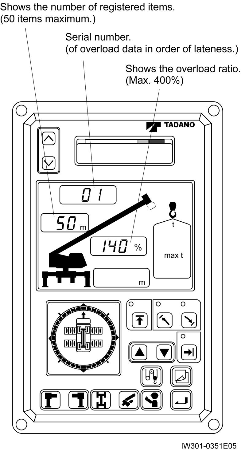
2. Overload History Display
The records of crane operations beyond overloading limit are displayed. You can choose between the displays of latest overload data and of the greatest overload data.
1. Select the main menu [ï Disp. O/L data ] in the adjustment mode, and press the register key to select the menu.
2. Use the scroll-up or scroll-down key until the menu of latest overload ratio or peak overload ratio appears. Select it by pressing the register key.
Display:
[:Disp. Late data ]
[:Disp. Max. data]
3. Display of latest overload data
The selection of [:Disp. Late data ] results in the latest registered overload history data being displayed. The time when overload history data has been registered is indicated in the moment display.
To view the next data on record (up to 50 items), press the scroll-down key.
Moment display
Display example: [99. 01. 23 12:35 ]
Functions of and How to Use Adjustment Mode
4. Display of greatest overload data
The selection of [:Disp. Max. data] results in the registered greatest overload history data being displayed.
The time when overload history data has been registered is indicated in the moment display. Press the scroll-down key, and load ratio, jib length, and jib angle will be displayed (jib length and jib angle are displayed only during the jib lift). Further press the scroll-down key, and the display will change into the next information (up to 10 items).
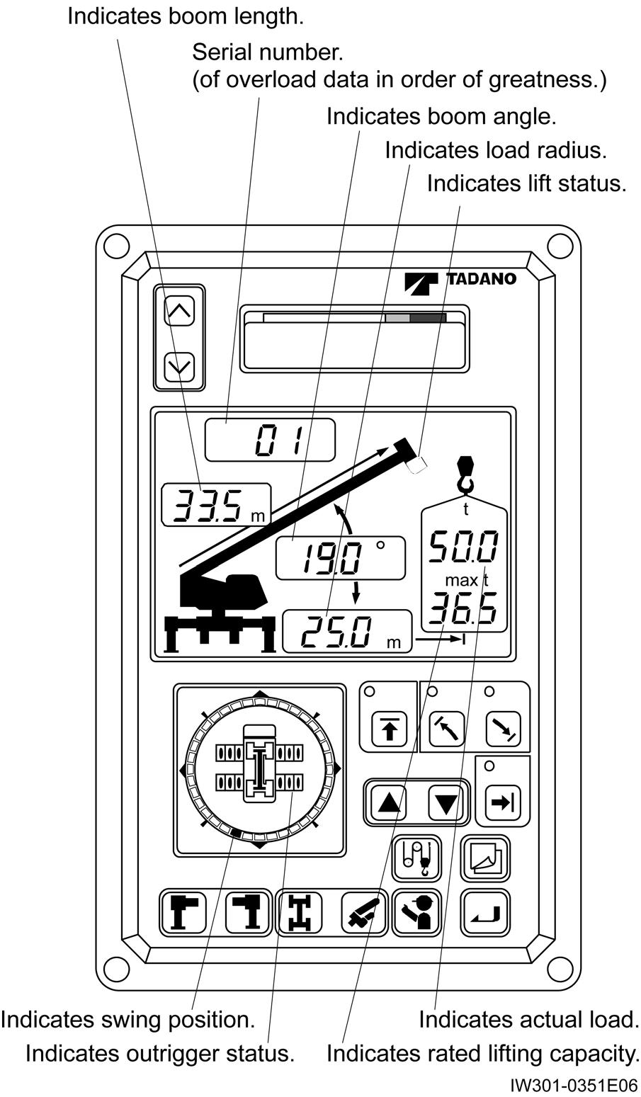
Moment display
Display example: [99. 01. 23 12:35 ]
[125% 14.5f 45.0 ]
3. Erasing the Overload History
[NOTICE]
When the AML main unit or EEPROM is replaced for repair and all adjustment is completed, erase-protect the overload history. Before delivering the machine to an user, erase-protect the overload history by erasing the latest history data three times.
You can erase the overload history data (record of crane operation when moment load ratio exceeds the set limit). Note that if the latest history data are erased three times, the menu will not appear, disabling the history data to be erased. At the time of the third erasure, the records of the greatest overload values will also be erased.
1. Select the main menu [ï Erase O/L data ] in the adjustment mode, and press the register key to select the menu.
2. Use the scroll-up or scroll-down key to display the overload history data item to be erased. Select it by pressing the register key. Display:
[:Erase Late dat ]
[:Erase Max. data]
3. When the message [Erase OK?] appears, press the register key to erase the data.
4. When the message [Done] appears, the overload record data is now erased. Press the display alteration key to exit the menu.
Functions of and How to Use Maintenance Mode
Functions of and How to Use Maintenance Mode
1. Program Version Display
ROM program version is displayed.
1. Select the main menu [ï Maintenance ] in the maintenance mode, and press the register key to select the menu.
2. When [:Prog. version ] is displayed, press the register key to select the menu.
3. When the below program version appears, press the display alteration key to exit the menu. Display example: [AML-L L0204 ] program version number
2. Data ID Number Display
Information of ROM data is displayed.
1. Select the main menu [ï Maintenance ] in the maintenance mode, and press the register key to select the menu.
2. Find the display [:Data ID. number ] by the scroll-up or scroll-down key, and then press the register key to select the menu.
3. Display changes by scroll-up or scroll-down key. Press the display alteration key to exit the menu. The ROM data is displayed as follows:
(1)ID number display: Indicates ROM ID number (revision number included). Display example:[750200 ]
(2)Specification number display: Indicates crane spec. number. Display example:[TR-500-3-00101 ]
(3)Code number display: Indicates parts code number of AML. Display example:[361-175-02000 ]
(4)Data date display: Indicates the date of making up data. Display example:[95, 12, 27 ]
(5)Revision date display: Indicates the date of data revision. Display example:[96, 01, 23]
3. Di Check
The input state of Di (external contact switch) is displayed.
1. Select the main menu [ï Maintenance ] in the maintenance mode, and press the register key to select the menu.
2. Press the scroll-up or scroll-down key until the display [:Di check ] appears, and then press the register key to select the menu.
3. Di input state is displayed. Display changes by scroll-up or scroll-down key. Press the display alteration key to exit the menu. Display example (Di1): [ 01 Over-wind of ]
Indicates switch state on : active of : not active
Switch name
Indicates Di input terminal number. 01 to 28 : Di 1 to Di 28
T : TC
A : ACC
No indication: Serial port input (Di from multiplex data transmitter and signal transmitter)
[NOTICE]
Switch state means on/off state which the AML program judges logically.
Usually, this matches to the physical condition of switch. However, if ìrî is added in front of the displayed ìonî or ìofî, these have different meanings as below.
ron: rof:
Logically switch is active, but physical contact is off.
Logically switch is not active, but physical contact is on.
Only the Di switch used for input in the program can be displayed. Since the display sequence of Di switch input states depends on the contents of the
Functions of and How to Use Maintenance Mode
program, the Di switch input states may not be indicated in the numerical order of Di switch input numbers.
4. Ai Check
The input state of Ai (analog detector input) is displayed.
1. Select the main menu [ï Maintenance ] in the maintenance mode, and press the register key to select the menu.
2. Press the scroll-up or scroll-down key until the display [:Ai check ] appears, and then press the register key to select the menu.
3. Ai input state is displayed. Display changes by scroll-up or scroll-down key. Press the display alteration key to exit the menu. Display example (ANAiNB): [ 02 Boom A 1201 ok ]
When detected input is within the normal input range, ìokî appears; when it is out of the range, then ìngî appears at this portion.
A/D converted value of analog input.
Analog detector name
Logical number of analog input in the program.
00:Moment input (MOINP, MOINN)
[NOTICE]
Only the Ai used for input in the program can be displayed. Since the display sequence of Ai input states depends on the contents of the program, the Ai input states may not be indicated in the numerical order of Ai input numbers.
5. Elevating Cylinder Oil Pressure Monitor
The cylinder extension lateral pressure and retraction lateral pressure which are detected for moment calculation are displayed.
1. Select the main menu [ï Maintenance ] in the maintenance mode, and press the register key to select the menu.
2. Press the scroll-up or scroll-down key until the display [:Disp ELEV PRES ] appears, and then press the register key to select the menu.
3. The elevating cylinder extension lateral pressure and retraction lateral pressure are displayed. Press the display alteration key to exit the menu. Display example:
07:Analog detector source (DET1SRC, DET2SRC)
08:Pressure input (ANAING)
09:Pressure input (ANAINH)
11 to 15:Serial port-1 analog input 1 to 5
(Ai from signal transmitter)
21 to 25:Serial port-2 analog input 1 to 5 (Ai from multiplex data transmitter)
Functions of and How to Use Maintenance Mode
6. Do Check
The output state of Do (Digital output: relay output and open collector transistor output) is displayed. Also, you can invert the current state of selected output.
1. Select the main menu [ï Maintenance ] in the maintenance mode, and press the register key to select the menu.
2. Press the scroll-up or scroll-down key until the display [:Do check ] appears, and then press the register key to select the menu.
3. Do output state is displayed. Display changes by scroll-up or scroll-down key. Press the display alteration key to exit the menu.
Display example (RLY1):
[ 00 Stoppage of ]
Current output state
Output name
Logical output port number
00 to 07:RLY1 to PLY8
(relay output)
10 to 17:TR1 to TR8
(open collector output)
7. MDT Monitor (Multiplex Data Transmitter Monitor)
The input/output state of the MDT (multiplex data transmitter) is displayed.
1. Select the main menu [ï Maintenance ] in the maintenance mode, and press the register key to select the menu.
2. Press the scroll-up or scroll-down key until the display [:MDT Monitor ] appears, and then press the register key to select the menu.
3. The input/output state of the MDT (multiplex data transmitter) is displayed. Display changes by increase or decrease key. Press the display alteration key to exit the menu.
Display example: [ No.123 Val. 1]
Input/output state
Digital input/output:
1:ON
0:OFF
Analog input/output: represented in numerals from 0 through 255.
Input/output number
[NOTICE]
Output state means on/off state which the AML program judges logically (same as the Di). Usually, this matches to the physical condition of switch. However, if ìrî is added in front of the displayed ìonî or ìofî, these have different meanings as below. ron:
Logically switch is active, but physical contact is off. rof:
Logically switch is not active, but physical contact is on.
4. During the above Do output monitoring procedure, output state will be inverted while you are pressing the check key.
[NOTICE]
For the signal represented by the displayed input/output No., see the ìMDT (Multiplex Data Transmitter) Input/Output Nos. and Corresponding Signalsî in the INFORMATION AND DATA section.
8. Key Switch Check
Check the key switch on the AML front panel whether it works normally or not.
1. Select the main menu [ï Maintenance ] in the maintenance mode, and press the register key to select the menu.
2. Press the scroll-up or scroll-down key until the display [:key SW check ] appears, and then press the register key to select the menu.
Functions of and How to Use Maintenance Mode
3. The display [ñ ñ ï ñ ñ ñ ñ ñ ñ] appears. Press any key other than the display alteration key, and the corresponding portion of display changes from ì-ì to ì î while you are pressing the key. Press the display alteration key to exit the menu.
9. Display Check

The segments of LCD panels and LEDs of the AML indicator repeat to go on and off.
1. Select the main menu [ï Maintenance ] in the maintenance mode, and press the register key to select the menu.
2. Press the scroll-up or scroll-down key until the display [:Display check ] appears, and then press the register key to select the menu.
3. The segments of LCD panels and LEDs of the AML indicator repeat to go on and off. Press the display alteration key to exit the menu and return to the ordinary display state.
10. Error Data Display
Error data registered in the AML are displayed on the moment indicator and display panel 1.
1. Select the main menu [ï Maintenance ] in the maintenance mode, and press the register key to select the menu.
2. Press the scroll-up or scroll-down key until the display [:Disp. err data ] appears, and then press the register key to select the menu.
3. The error codes are displayed on the moment indicator and display panel. Press the display alteration key to exit the menu and return to the ordinary display state.
(1)The moment indicator displays the time when error occurred. Display example: [ 96. 01. 23 12:35 ]
(2)When the scroll-down key, the time display changes to the error code display.
Display example: [ Error:2003 ]
(3)The mark ì î on the error code display shows the another errors exist. Press the scroll-down key to display the next error code.
11. Erasing the Error Data
Use this menu to erase the registered error data information.
1. Select the main menu [ï Maintenance ] in the maintenance mode, and press the register key to select the menu.
2. Press the scroll-up or scroll-down key until the display [:Erase err data ] appears, and then press the register key to select the menu.
3. When the message [Erase OK? ]appears, press the register key.
4. When the message [Done] is displayed, the error data is now erased. Press the display alteration key to exit the menu.
Functions of and How to Use Maintenance Mode
12. Option Board Check
The state of the incorporated option board (analog output, wire detection) is indicated.
1. Select the main menu [ï Maintenance ] in the maintenance mode, and press the register key to select the menu.
2. Press the scroll-up or scroll-down key until the display [:OP board check ] appears, and then press the register key to select the menu.
3. The sort of the incorporated option board is displayed (Up to two option boards can be incorporated). Display changes by scroll-up or scroll-down key. Press the display alteration key to exit the menu.
Display example:
[ 1 Valve control ]
Option board name
(1 valve control : Circuit board for analog output)
(2 Rope LGTH DET : Circuit board for detecting wire rope movement to indicate hook block position)
13. Ao Check
The Ao (analog output) state is displayed with an output value of the specified percentage.
1. Select the main menu [ï Maintenance ] in the maintenance mode, and press the register key to select the menu.
2. Press the scroll-up or scroll-down key until the display [:Ao check ] appears, and then press the register key to select the menu.
3. Ao output state is displayed as below. Display changes by scroll-up or scroll-down key. Press the display alteration key to exit the menu. Display example (CNTL1PïCNTL1N):
[ 41 SWG RV 0 0 ]
Output level for checking indicates at what percentage of the maximum level the value is to be output.
Output level indicates at what percentage of the maximum level the value is being output.
Output name
Ao output terminal number
11-19:Output to serial port 1
(Signal transmitter)
21-29:Output to serial port 2
(Multiplex data transmitter)
41-49:Output to option board
(41:CNTL1P ï CNTL1N)
(42:CNTL2P ï CNTL2N)
(43:CNTL3P ï CNTL3N)
(44:CNTL4P ï CNTL4N)
[NOTICE]
Only the Ao used for output in the program can be displayed. Since the display sequence of Ao output states depends on the contents of the program, the Ao output states may not be indicated in the numerical order of Ao output numbers.
4. How to see the output values for checking
Using the increase or decrease key while the Ao output state is displayed, set up an output level for
Functions of and How to Use Maintenance Mode
checking. Every time you press the key, the level is increased or decreased by 1%. When the key is held down for more than one second, the level is increased or decreased by 10% for the increase key and by 5% for the decrease key. When the level exceeds 100%, it returns to 0% (conversely, when the level reaches 0%, it returns to 100%.)
5. How to output the output values for checking While the output level for checking is indicated, press the check key; output level for checking will be output while the key is held down. The displayed output level value blinks.
14. Sio Check
The Sio (serial port) state is indicated.
1. Select the main menu [ï Maintenance ] in the maintenance mode, and press the register key to select the menu.
2. Press the scroll-up or scroll-down key until the display [:Sio check ] appears, and then press the register key to select the menu.
3. Serial port state is displayed. Display changes by scroll-up or scroll-down key. Press the display alteration key to exit the menu. Display example:
[Serial port1 OK ]
Serial port state
OK : Normal
NG : Abnormal
NU : Not used
Serial port name
(Serial port 1:serial communication circuit to signal transmitter)
(Serial port 2:serial communication circuit to multiplex data transmitter)
15. Adjust Monitor
The same items as shown in the [ï Adjust ] menu of the main menu of the adjustment mode appears. However, adjustment is not available.
1. Select the main menu [ï Maintenance ] in the maintenance mode, and press the register key to select the menu.
2. Press the scroll-up or scroll-down key until the display [:Adjust Monitor ] appears, and then press the register key to select the menu.
3. The same items as shown in the [ï Adjust ] menu of the main menu of the adjustment mode are displayed. Press the display alteration key to exit the menu.
16. Overload History Display
The overload history display in the maintenance mode has the same function as that of in the adjustment mode.
See the ìOverload History Displayî in the ìFunctions of and How to Use Adjustment Modeî section.
17. Erasing the Overload History
Erasing the overload history in the maintenance mode has the same function as that of in the adjustment mode.
See the ìErasing the Overload Historyî in the ìFunctions of and How to Use Adjustment Modeî section.
18. Clock Adjustment
Clock adjustment is included in the functions of the maintenance mode. However, see the ìClock Adjustmentî in the ìFunctions of and How to Use Adjustment Modeî section for how to adjust the clock.
Error Message
1. Display of Error Message [NOTICE]
The language (English or Japanese) of error message is selected at the [ï Language] menu in the adjustment mode.
2. How to Read the Error Message
1. Error code in the error message is represented by four-digit codes.
Error code: E1 E2 E3 E4 lndividual code
Group code
0:Alarm
1:Abnormal communication
2:Abnormal detector
3:Abnormality inside AML
2. The highest rank (E1 in the above figure) indicates error groups. The each next three digit figure (E2 through E4 above) indicates individual error code under error groups.
1. If AML system detects the trouble in ordinary use (user mode), it makes beep sound as well as displays error message on the moment display. Display example: [Error:2001]
Shows that an error of error code 2001 has occurred.
2. This error message display continues till the cause is eliminated.
3. While the adjustment or maintenance mode is being used, only beep sound informs the operator of the occurrence of trouble. The display on the moment display, however, does not change to the error message display automatically. Current message keeps displayed.
4. To confirm the error message in the adjustment or maintenance mode, press the lift height limit key. While you are pressing the key, the error message is shown on the moment display. (It may take some seconds for the display to change.)
5. If trouble remains even when you return to the user mode after exiting adjustment or maintenance mode, corresponding error message appears on the moment display.
3. Since group code ì0î indicates a warning condition, it does not always mean that there is a problem in the system when an error message is displayed.
4. For this reason, warning-related error messages are not registered in the systemís error history memory. Warning-related error messages are shown in the moment display in the same way as message for other group codes.
3. How to Read the Error History
1. Error history records 50 errors, maximum, of the group code, in order of occurrence. Those beyond 50 will be made to disappear in the order of occurrence.
2. See the ìError Data Displayî in the ìFunctions of and How to Use Maintenance Modeî section for reading the error history.
4. Troubleshooting Table
4.1 Group Code 0
Message Description
Warning : 0001
Warning : 0002
Warning : 0003
Warning : 0004
Error Message
Right front outrigger beam retraction
Right rear outrigger beam retraction
Left front outrigger beam retraction
Left rear outrigger beam retraction
Situation: Outrigger beam has retracted and O/R extended width decreases, close to the lifting capacity change over point.
Cause: Outrigger beam(s) have just retracted.
Action: Extend the outrigger beam again.
Message Description
Error : 0005 Boom angle value becomes out of specified range
Situation: Boom extension automatically stops during setting of the side-up jib. (Only applicable to the machines with side-up jib)
Cause: Boom angle is smaller than that required for jib setting.
Action: Raise the boom till safety angle for jib setting.
Message Description
Error : 0006 Improperly inserted jib lock pin
Situation: Boom extending operation automatically stops during setting or stowing of the side-up jib. (Only applicable to the machines with side-up jib)
Cause: Jib lock pins are in incorrect states.
(Jib lock, jib set and automatic lock pins have been inserted)
Action: Correct the lock pins property inserted.
Message Description
Warning : 0010 Close to the swing angle restriction
* The error code is applicable only to models with the slow swing stop function.
Situation: The boom is just close to the swing restriction angle.
Cause: The swing area restriction function is active, and the boom has been swung to a point just close to the limit. (The error code will remain displayed as long as the boom is in close to the limit for both left and right swing operation)
Error code is displayed only when the slow swing stop function is canceled. (swing is not automatically stopped)
Action: Swing the boom away from the swing restriction point. Cancel the swing area restriction function.
Message Description
Warning : 0012
Error Message
Rear stability auto. stop range
Situation: The rearward tipping load limit lowers below the current lifting load as the boom is swung.
Cause: The boom is raised too high. The outrigger extension width is insufficient.
Action: Lower the boom. Increase the outrigger extention width.
Message Description
Error : 0013
Error : 0014
Over-front detection switch is defective
Over-front or over-rear detection switch is/are defective
Situation: The swing angle does not conform with the condition detected by the over-front detection switch.
Over-front switch has detected as front though boom doesnot turn front. (Obtains capacity of over-front detection switch as not in front.)
Cause: Over-front detection switch is defective, over-front and/or over-rear detection switch is/are defective, or its wiring is open. Swing angle detector is defective or maladjusted.
Action: Investigate the possible causes described above. The input status can be checked with ìAi & Di checkî function from the ìMaintenanceî menu.
Message Description
Warning : 0015
Overwinding condition (When overwinding stop function is cancelled)
Situation: Overwinding detection switch has been turned off (overwinding status).
A crane does not stop automatically though the error code is displayed when overwinding is cleared.
Cause: Main or auxiliary hook block has been wound up excessively. Action: Hoist down the main or auxiliary winch.
Message Description
Error : 0016
Error : 0017 State 1 is not applied (Outrigger, Swing angle, CW, combinations) State 2 is not applied (Boom and Jib combination)
Situation: Crane is automatically stopped while the outrigger, boom, jib and counterweight settings are out of the allowable condition, and operation toward a critical conditions is attempted.
Cause: The outrigger, boom, jib and counterweight settings are improper.
Action: Register the operation status again.
Message Description
Error : 0018
Error : 0019
Error : 0020
Error : 0021
Error Message
Boom (3rd-top boom sections for TR-300XL-4) full retraction switch 1 faulty Boom full retraction switch 2 faulty Boom full retraction switch 3 faulty Boom full retraction switch 4 faulty
Situation: Crane is automatically stopped when operation toward a critical condition is performed, when the specified boom section full retraction detector switch does not detect full retraction while the specified boom section is fully retracted, or vice versa.
Cause: Boom full retraction detection switch is faulty, or its wiring is open. Boom length sensor is defective or maladjusted. The AML itself is defective.
Action: Perform inspection for the possible causes listed above. The input status can be checked with ìAi & Di checkî function from the ìMaintenanceî menu.
Message Description
Warning : 0023 Stopped at 100% of crane performance
Situation: Because the crane performance has exceeded 100%, a crane is automatically stopped when hoisting-up, boom lowering or boom extending is performed.
Cause: The allowable lifting capacity is exceeded.
Action: Perfrom either of hoisting-down, boom raising, or boom retracting.
Message Description
Warning : 0024 Stop due to two-blocking
Situation: Crane is automatically stopped when operation toward a critical condition is performed while the two-blocking detection switch is turned off (Two-blocking status).
Cause: Main or auxiliary winch hook block has been wound up excessively.
Action: Hoist down the main or auxiliary winch.
Message Description
Warning : 0025 Stopped due to backward stability
Situation: The crane is in a state where the backward stability is not assured, boom raising/retracting operation should be stopped automatically.
Cause: The boom angle is too large, or the boom length is insufficient. The outrigger extension width is too small.
Action: Lower the boom, extend the boom, or increases the extension width of outriggers.
Error Message
Message Description
Warning : 0026 Stopped at upper boom angle limit restriction
Situation: Crane operation is automatically stopped when operation toward a critical condition is attempted while boom angle exceeds the upper limit.
Cause: The upper boom angle limit restriction is set, and the boom angle has exceeded the limit.
Action: Lower the boom. Cancel the upper boom angle limit restriction.
Message Description
Warning : 0027 Stopped at lower boom angle limit restriction
Situation: Crane operation is automatically stopped when operation toward a critical condition is attempted while boom angle exceeds the lower limit.
Cause: The lower boom angle limit restriction is set, and the boom angle has exceeded the limit.
Action: Raise the boom.
Cancel the lower boom angle limit restriction.
Message Description
Warning : 0028 Stopped at lifting height restriction
Situation: Crane operation is automatically stopped when operation toward a critical condition is attempted while lifting height exceeds the limit.
Cause: The lifting height limit restriction is set, and the top boom headís height has exceeded the limit.
Action: Lower or retract the boom. Cancel the lifting height restriction function.
Message Description
Warning : 0029 Stopped at load radius restriction
Situation: Crane operation is automatically stopped when operation toward a critical condition is attempted while the load radius exceeds the limit.
Cause: The load radius restriction is set, and the load radius has exceeded the limit.
Action: Raise or retract the boom. Cancel the load radius restriction function.
Error Message
Message Description
Warning : 0034
Warning : 0035 Stopped by main winch over-unwinding prevention device Stopped by aux. winch over-unwinding prevention device
Situation: Hoisting-down is automatically stopped by over-unwinding prevention device as the main/aux. wire rope on the winch drum is drawing to the end.
Cause: The number of wire rope part line on the hook block is wrong. The hook block position is too low.
Action: Adjust the number of part line as specified, or perform winch winding operation.
Message Description
Error : 0037
Defective accumulator pressure (sensor)
Situation: Abnormal accumulator pressure is detected. (Only for models with accumlator pressure detector)
(This message does not relate to the control by the AML)
Cause: Accumulator pressure is too low.
Accumulator pressure detector is defective, or its wiring is open. AML (analog circuit board) is defective.
Action: Perform inspection for the possible causes listed above. The status of any input from the detector can be checked using the ìAi checkî function from the ìMaintenanceî menu.
Message Description
Error : 0041
Warning : 0078
Wrong counterweight state registered Altered counterweight state
Situation: Crane operation is automatically stopped when operation toward a critical condition is attempted when the detected counterweight status is different from the registered one. (Applicable only to the error code 0041) (Crane does not stop automatically when ìWarning:0078î is displayed)
Cause: Defective counterweight state detector, improper installation or adjustment of the detector, open wiring of the detector circuit. Altered combination of the counterweight.
Action: Search for the cause of the detector defect. The status of any input from the detector can be checked using the ìDi checkî function from the ìMaintenanceî menu. Register the counterweight state again.
Message Description
Warning : 0042
Warning : 0043
Right swing restriction limit
Left swing restriction limit
Situation: Boom is swing to a point exceeding the swing restriction limit setting. Crane is automatically stopped if swing automatic stop function is provided.
Cause: The swing restriction limit function is set, and swing position has been exceeded the limit.
Action: Swing the boom in the opposite direction to the setting. Cancel the swing restriction function.
Error Message
Message Description
Warning : 0046 Condition setting altered
Situation: Crane state has changed.
Cause: Outrigger jacks have been retracted.
Action: Register operation status again.
Message Description
Warning : 0047 Hook block contacts to the elevating cylinder
Situation: Hook block approaches the space where it can hit the elevation cylinder rod.
Cause: Boom raised too high while it is almost fully retracted.
Action: Extend or lower the boom.
Message Description
Warning : 0056 Swing operation is dangerous
Situation: The lifting capacity will be exceeded if the boom is swung further.
Cause: The boom has been swung to a point just before the region where the capacity is reduced in retraction with outrigger extension width.
Action: Swing the boom in the opposite direction. Retract or raise the boom so that the lifting capacity will not be exceeded.
Message Description
Warning : 0057
Warning : 0058
Warning : 0059
Warning : 0060
Right front outrigger state change
Right rear outrigger state change
Left front outrigger state change
Left rear outrigger state change
Situation: Outrigger state has changed as to decrease extension. Crane performance shifted to that with a smaller outrigger extension width. A crane does not stop automatically.
Cause: Outrigger extension width has decreased unintentionally.
Action: If reduced capacity does not matter, continue to use the crane. If the capacity is expected to be exceeded, re-extend the outrigger further and register working state again.
Message Description
Error : 0067
Warning : 0113
Error Message
Abnormal moment [Strain gauge detector] Does not stop
Abnormal moment [Pressure sensor detector] Can not operate to dangerous direction
Situation: Actual lifting load display value calculated in the AML becomes a minus value because of an abnormal moment detector. Therefore, re-adjustment of the moment detector is required.
(0067: Only warning, automatic stop does not work)
(0113: Crane operation is stopped when operation toward a critical condition is attempted)
Cause: Abnormal detectors (Boom length detector, strain gauge type and/or pressure sensor type moment detector).
Maladjusted detector.
Abnormal AML main body (Analog board).
[Warning : 0113] Moment value can not be detected because the elevating cylinder has retracted to the stroke end.
* This warning (0113) is output when actual lifting load display value that calculate in the AML becomes a minus value. Abnormal minus load value is difference due to the boom condition.
Action: Readjust the corresponding detector (pressure sensor). Investigate the detector which seems to be defective. Input status from the detector can be confirmed by ìAiî check of ìMaintenanceî menu and ìElevating cylinder pressure monitorî.
(ìAiî check related items: [Boom L], [Boom A], [MMT V], [DRC EXT], [DRC RTR] etc.)
Raise the boom. (error code: In case of 0113)
Message Description
Error : 0068
Error : 0069
Error : 0070
Error : 0071
Error : 0072
Error : 0073
Error : 0074
Situation:
Abnormal swing angle
Abnormal boom length
Abnormal boom angle
Abnormal extension width of the right front outrigger
Abnormal extension width of the right rear outrigger
Abnormal extension width of the left front outrigger
Abnormal extension width of the left rear outrigger
The detected value from the corresponding detector is out of the normal range and the detector requires readjustment.
Alarm is output but automatic stop does not work. For the errors which cause automatic stop, see the fllowing ones.
Abnormal swing angle
Abnormal boom length
Abnormal boom angle
Message : 2016 - 2019, 2021
Message : 2007, 2008
Message : 2004
Abnormal outrigger extension widthMessage : 2009 ñ 2012
Cause: Misadjastment or misalignment.
Improper installation of the detector.
The AML itself is defective. (Analog board is defective)
Action: Readjust the corresponding detector. Insrall the corresponding detector properly and readjust it. If the detectors are not defective, replace the AML main unit (analog board).
Error Message
Message Description
Warning : 0075 Spring lock state has changed
Situation: Spring lock state has changed. (Only for models with spring lock state detection)
Cause: Spring lock released unintentionally. Spring lock has been released by mistake.
Action: Set spring lock again.
Message Description
Warning : 0077 Altered front or rear jack state
Situation: The actual front or rear jack state has changed from the registered one. (Only for models with spring lock state detection)
Cause: Front or rear jack has operated. Defective detector.
The AML itself is defective. (Analog board is defective)
Action: Return the front or rear jack to the original condition. Check the detector using ìDi checkî function on ìMaintenanceî menu.
Message Description
Warning : 0078 Altered counterweight state (refer to 0041)
Message Description
Warning : 0081 Elevation motion slowing down
* This error code is applicable only to models with the slow elevation stop function.
Situation: The boom elevation slow stop function is activated, slowing down boom elevation motion.
Cause: The boom has been elevated close to a stop angle (100% stop, restriction limit stop, stroke end stop, or rear stability stop), and the elevation slow stop function has been activated, and the elevation speed is reduced. (The error code is displayed only when the boom is being elevated)
Action: Stop operating the boom.
Operate the boom in the opposite direction, whether it is rising or lowering. Cancel the boom angle limit restriction function. Move the boom to the non-critical side.
Message Description
Warning : 0082 Swing motion slowing down
* This error code is applicable only to models with the slow swing stop function.
Situation: The slow swing stop function is activated, slowing down boom swing motion.
Cause: The boom has swung close to a stop angle (either 100% stop or range limit stop) and the slow swing stop function has been activated, and swing speed is reduced. (The error code is displayed only when the boom is being swung to the left or right)
Action: Stop the swing operation. Swing away from the limit.
Retract or raise the boom so that the lifting capacity will not be exceeded. Cancel the swing limit restriction function.
Error Message
Message Description
Warning : 0085 Elevation stopped at stroke end
* Applicable to the models with the oil pressure detection method.
Situation: Crane operation is automatically stopped when operation toward a critical condition is attempted while boom elevating operation is stopped due to elevation stroke end.
Cause: Boom elevating is automatically stopped just before the elevating cylinder stroke end because the moment cannot be detected correctly by the oil pressure in the elevating cylinder if the cylinder is reached/extended to stroke end.
Action: Stop operation which has caused automatic stop. Operate the boom in the opposite direction which has caused automatic stop.
Message Description
Warning : 0088 Stopped at jib limit
* This error code is applicable only to models with jib extension status monitoring.
Situation: Crane operation is automatically stopped when operation toward a critical condition such as hoisting-up, lowering or extending the boom is attempted.
Cause: In the state of AML setting to boom while extending the jib, is exceeding the lifting capacity.
Action: Perform operation toward non-critical condition, such as hoisting-down, raising or retracting the boom.
Message Description
Warning : 0113 Abnormal moment [Pressure senser detector] (refer to 0067)
Message Description
Warning : 0117 Boom contact warning
Situation: The boom approaches the mirror or engine cover, etc.
Cause: The boom, stowing jib and/or elevating cylinder approach (es) the mirror or engine cover etc. of the carrier, there is a possibility to come in contact if operating the boom lowering or swinging further.
Action: Operate watching the obstacles when operating the boom lowering or swinging.
Error Message
4.2 Group Code 1
Message Description
Error : 1001
Error : 1002 Serial port transmission line 1 open Selial port transmission line 2 open
Situation: All operations except boom swing are unavailable because the transmitter cannot receive any signal from the AML.
Cause: A part of wiring to the transmitter is open. The connector pins of wiring to the transmitter are in poor contact. The receiving circuit of transmitter or the transmitting circuit of AML is defective.
Action: Check the wiring to the transmitter for continuity. If no continuity exists, replace or repair the wiring. Replace the transmitter or AMLís power circuit board.
Message Description
Error : 1003
Error : 1004 Serial port receiving line 1 open Serial port receiving line 2 open
Situation: All operations except boom swing are unavailable because the AML cannot receive any signal from the transmitter.
Cause: The line from the transmitter includes open wiring or poorly contacting connection. The transmitter is not connected (the connector is disconnected). The receiving circuit of AML or the transmitting circuit of transmitter is defective. The serial port fuse (SIF1, 2) of AML has blown.
Action: Check the wiring to the transmitter for continuity. If no continuity exists, replace or repair the wiring.
Replace the transmitter or AMLís power circuit board. Replace the serial port fuse of AML.
Message Description
Error : 1005
Error : 1006
Transmitter 1 defect
Transmitter 2 defect
Situation: All operations except boom swing are unavailable due to the faulty transmitter.
Cause: The internal circuit of transmitter is defective.
Action: Replace the defective transmitter.
Message Description
Error : 1007
Error : 1008
Error : 1009
Error : 1010
Error Message
Transmitting data error at serial port 1
Transmitting data errot at serial port 2
Receiving data error at serial port 1
Receiving data error at serial port 2
Situation: All operations except boom swing are unavailable due to a discrepancy between the data transmitted/received by the AML and the data received/transmitted by the transmitter.
Cause: The data has been garbled due to noise (external radio wave interference). The signal wire connection is in poor contact.
Action: Turn off any device which is emitting strong noise. Check the signal wire for poor connection. Repair or replace the wiring as appropriate.
Message Description
Error : 1011
Error : 1012
Transmitter type improper (serial port 1)
Transmitter type improper (serial port 2)
Situation: All operations except boom swing are unavailable due to the wrong transmitter connected to the serial port.
Action: Connect a proper transmitter to the serial port.
Error Message
4.3 Group Code 2
Message Description
Error : 2001 Moment detector trouble
Situation: All operations except boom swing are unavailable due to the abnormal input value from the moment detector.
Cause: The moment detector is defective, or its wiring is open. The AML itself is defective.
Action: Perform inspection for the possible causes listed above. The status of any input from the detector can be checked using the ìAi checkî function from the ìMaintenanceî menu.
Message Description
Error : 2003 Boom length detector trouble
Situation: All operations except boom swing are unavailable due to the abnormal input value from the boom length detector.
Cause: The boom length detector is defective, or its wiring is open. The AML itself is defective.
Action: Perform inspection for the possible causes listed above. The status of any input from the detector can be checked using the ìAi checkî function from the ìMaintenanceî menu.
Message Description
Error : 2004 Boom angle detector trouble
Situation: All operations except boom swing are unavailable due to the abnormal input value from the boom angle detector.
Cause: The boom angle detector is defective, or its wiring is open. The AML itself is defective.
Action: Perform inspection for the possible causes listed above. The status of any input from the detector can be checked using the ìAi checkî function from the ìMaintenanceî menu.
Message Description
Error : 2005 Jib length detector trouble
Situation: All operations except boom swing are unavailable due to the abnormal input value from the jib length detector.
Cause: The jib length detector is defective, or its wiring is open. The transmitter unit is defective.
Action: Perform inspection for the possible causes listed above. The status of any input from the detector can be checked using the ìAi checkî function from the ìMaintenanceî menu.
Error Message
Message Description
Error : 2006 Jib angle detector trouble
Situation: All operations except boom swing are unavailable due to the abnormal input value from the jib angle detector.
Cause: The jib angle detector is defective, or its wiring is open. The transmitter unit is defective.
Action: Perform inspection for the possible causes listed above. The status of any input from the detector can be checked using the ìAi checkî function from the ìMaintenanceî menu.
Message Description
Error : 2009
Error : 2010
Error : 2011
Error : 2012
Right front outrigger length detector trouble
Right rear outrigger length detector trouble
Left front outrigger length detector trouble
Left rear outrigger length detector trouble
Situation: The input data from the outrigger length detector are abnormal.
Cause: The outrigger length detector is defective, or its wiring is open. The AML outrigger length detector is maladjusted. (For multiplex data transmitter) The transmitter unit is defective.
Action: Perform inspection for the possible causes listed above. The status of any input from the detector can be checked using the ìAi checkî function from the ìMaintenanceî menu.
Message Description
Error : 2017
Error : 2019
Swing angle detector 1 trouble (swing dead angle switch OFF)
Swing angle detector 2 trouble (swing dead angle switch ON) (same as swing angle detector 1,2 select switch)
Situation: All operations except boom swing are unavailable due to the input data from the swing angle detector inconsistent with the swing dead angle detector switch position.
Cause: Swing angle detector is faulty or maladjusted, or its wiring is open. Swing dead angle detector switch is faulty or maladjusted, or its wiring is open. The AML itself is defective.
Action: Perform inspection for the possible causes listed above. The status of any input from the detector can be checked using the ìAi & Di checkî function from the ìMaintenanceî menu.
Error Message
Message Description
Error : 2021 Swing angle detector offset trouble
Situation: All operations except boom swing are unavailable due to the abnormal offset value of the swing angle detector 1 or 2.
Cause: The swing angle detector is faulty. The AML itself is defective.
Action: Perform inspection for the possible causes listed above. The status of any input from the detector can be checked using the ìAi checkî function from the ìMaintenanceî menu.
Message Description
Error : 2022
Error : 2023 Boom elevation cylinder extension pressure detector trouble Boom elevation cylinder retraction pressure detector trouble
Situation: All operations except boom swing are unavailable due to the abnormal input value from the oil pressure detector in the boom elevating cylinderís extension/retraction chamber.
Cause: The pressure detector is defective, or its wiring is open. The AML itself is defective.
Action: Perform inspection for the possible causes listed above. The status of any input from the detector can be checked using the ìAi checkî function from the ìMaintenanceî menu.
( ìAi checkî related items : [DRC EXT], [DRC RTR]
4.4 Group Code 3
Message Description
Error : 3003
Error Message
System trouble (sum check error)
Situation: All operations except boom swing are unavailable because ROM has been found abnormal as a result of sum check.
Cause: The AMLës CPU board is defective. ROM defective.
Action: Replace the AMLís CPU board. Replace ROM.
Message Description
Error : 3006
System trouble (EEPROM defect)
Situation: All operations except boom swing are unavailable because AML cannot write on its nonvolatile memory (EEPROM).
Cause: The AMLís CPU board is defective. EEPROM is defective.
Action: Replace the AMLís CPU board or EEPROM.
Message Description
Error : 3007
Error : 3008
Error : 3009
Error : 3011
Error : 3012
Error : 3013
Error : 3017
System trouble (RAM trouble)
System trouble (RAM trouble)
System trouble (CPU trouble)
System trouble (bus error)
System trouble (address error)
System trouble (unauthorised instruction)
System trouble (privilege violation)
Situation: All operations except boom swing are unavailable because software program cannot run normally.
Cause: The AMLís CPU board is defective.
Action: Replace the AMLís CPU board. If this error has occurred, the relevant error message is displayed and the AML stops processing. (There is a continuous beep and two LEDs in the adjustment window illuminate)
While the AMLís CPU board is suspected to be defective, check the inside of the AML for any abnormality such as loose connectors.
Message Description
Error : 3010
System trouble (A/D converter trouble)
Situation: All operations except boom swing are unavailable due to abnormal input to the A/D converter.
Cause: AMLís CPU board and/or analog board are defective. Wiring for the analog defector is abnormal (short-circuit).
Action: Replace the AMLís CPU board and/or analog board. Check the connection (resistance) of analog detectors (one connected with AML itself).
Disassembly of AML Main Unit
Disassembly of AML Main Unit
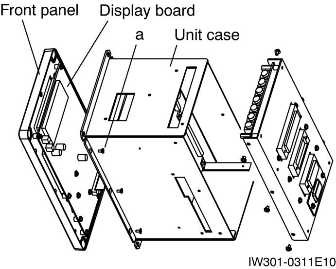
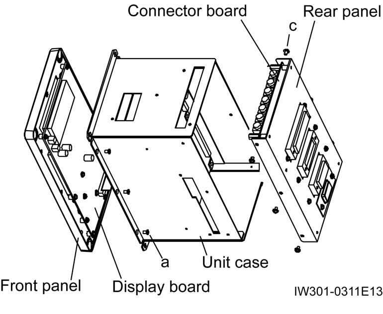
1. Removing Front Panel/Display Board
[NOTICE]
◆Do not touch each front and rear face of the boards by hand when removing the boards.
1. Take off the front panel and display board as an assembly from the unit case by unscrewing screw(a).

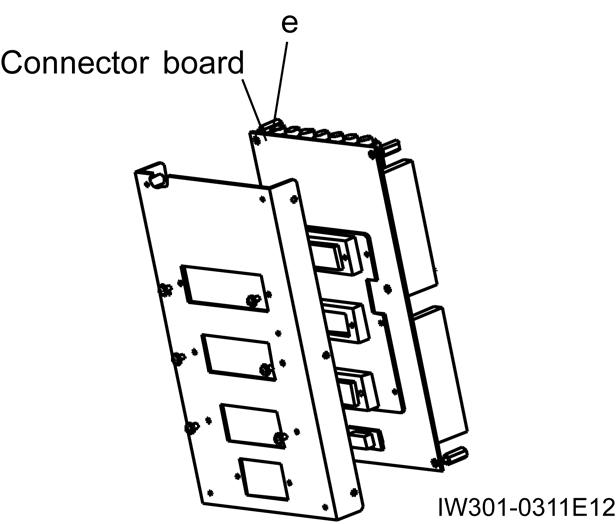
2. Removing Rear Panel/Connector Board
[NOTICE]
◆Do not touch each front and rear face of the boards by hand when removing the boards.
1. Take off the rear panel and connector board as an assembly from the unit case by unscrewing screw(c).
2.
Display board b
IW301-0131E20
2. Remove the spacer(e) and separate the connector board.
Disassembly of AML Main Unit
3. Removing CPU Board/Analog Board /Power Board
[NOTICE]
◆Do not touch each front and rear face of the boards by hand when removing the boards.
1. Take off the front panel and display board as an assembly from the unit case by unscrewing screw(a). Then take off the rear panel and connector board as an assembly from the unit case by unscrewing screw(c).
3.1 Notes on ROM/EEPROM Replacement
[NOTICE] h g f
◆EEPROM stores the adjustment values for each specification number. When replacing the CPU board, reuse the EEPROM after removing it from the broken CPU board.
When replacing ROM and EEPROM, make sure that the concavities of IC and socket meet each other.
2. Take off the CPU Board by unscrewing screw(f). Then remove the spacer(h) and take off the analog board and power board as an assembly from the unit case. Next, separate the analog board by removing nut(g).
CPU board
Adjustment Value Table (TL-300E-3)
[INFORMATION AND DATA]
Adjustment Value Table (TL-300E-3)
Specification No. : TL-300E-3-00107 (2M2D-specification)
AML model : AML-L D
AML code No. : 361-922-00000
1. Setting before adjustment
2. Adjustment the detector
Precautions for adjustment
(*1) Adjust the center of dispersion to coincide to the adjusting value.
(*2) Adjust the boom angle and the moment in the elevating lowering operation.
(*3) Adjust the swing angle in the clockwise swing operation.
(*4) When adjusting the moment, make the number of parts of line to the standard number (four parts of line) that is when boom fully extended, and set the AML as Boom status: Boom and Number of parts of line:4.


