1 minute read
Model 9600/9700 Swing-Reach ® Lift Truck
Reach Manifold
The Reach manifold is located above the fork assembly. The following components are installed on the manifold:
SOL11 (Reach Select) - routes oil to the reach cylinders.
CB1, CB2 - used to retain oil in the rotate actuator until a rotate function is requested.
REL5 - used to limit system pressure in the rotate actuator even when the function is not activated.
Load Handler Proportional Valves (SOL7 Traverse PWM, SOL8 Rotate PWM)
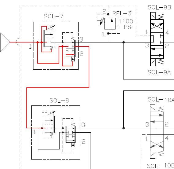
The PWM Solenoids are physically one unit that performs two functions. One function allows oil that is not being used to flow through the valve with minimal resistance (Coil Not Activated). The other function controls the flow going to a load handler function (Coil Activated).
SOL7, SOL8 - Coil Not Activated
When the SOL7 coil is not activated and the Load Handler Motor is running, the pump output flows through the mesh screen to Port 1. The pressure increase causes the pilot line directly connected to Port 1 to shuttle and provide a path for fluid to flow through Port 2 to SOL8, Port 1. If SOL8 is not activated, the same scenario occurs at SOL8.

Section 8.Theory of Operation
Hydraulic Components
Publication: 1089040, Issued: 08 Apr 2016
SOL7, SOL8 - Coil Activated
When SOL7 is activated, Solenoid 7 fluid passes through port 3 to the SOL9A DirA and SOL9B DirB valve. The greater the coil field strength, the more the valve opens, allowing more fluid to flow to the directional valve. The flow going to the directional valve activates the pilot line that deals with shuttling fluid between ports 2 and 3. The remaining pump output can shuttle SOL7 to provide fluid to SOL8.
Section 8.Theory of Operation
Hydraulic Components 8-14
Model 9600/9700 Swing-Reach ® Lift Truck
Publication: 1089040, Issued: 08 Apr 2016


