4 minute read
Section 7.Component Procedures
Model 9600/9700 Swing-Reach ® Lift Truck
MotorsElectrical Components
7.While gently pulling the scale outward, slowly pull the paper strip in the direction that the commutator normally rotates.
8.When the paper strip begins to move freely, the spring scale will read the spring brush tension.
9.Refer to Table7-6 for correct spring tension.
Table 7-6.Minimum Brush Length and Spring Tension
4.With minimal pressure, run the stone back and forth across the commutator until it is polished. Do not pass stone over the ends of the commutator segments.
5.Thoroughly blow out the motor with compressed air.
6.Inspect commutator. Reinstall the brush or armature and cover.
7.Check operation.
AC Motor Service Temperature Sensor Replacement Traction Motor
1.Turn the key switch OFF and disconnect the battery connector.
10.Repeat steps 3 thru 9 for the remaining brushes.
Polishing the Commutator
NOTE: Use a narrow masking tape (1/2 to 3/4in. wide) and wrap the stone in a spiral configuration, leaving only enough stone exposed to make contact with the commutator. As the length of the stone becomes shorter with use, peel back and remove portions of the tape.
Make sure loose clothing is tied back. Do not wear jewelry. Wear insulated gloves.
1.If the motor has 4 or more brushes, remove an accessible brush from the motor with the motor still installed in the truck. If the motor only has 2 brushes or the commutator is not accessible with the stone, the armature must be installed in a lathe or replaced. If so, go to step 4.
2.Activate the motor.
3.With the motor turning, carefully insert the commutator stone into the brush box area.
2.Remove the brake assembly.
3.Disconnect the temperature sensor connector.
4.Disconnect motor power cables. Note locations for reassembly later.
5.Remove the terminal board.
6.Remove the four bolts that secure the top end bell to the bottom end bell.
7.Remove the top end bell using a puller.
8.Cut the bad temperature sensor cable.
9.Install new temperature sensor with high temperature silicon e P/N1110785/716. Mount the sensor close to the location of the original. Secure the cable with a cable tie to one of the power leads for stress relief.
10.Reinstall the top end bell.
11.Reinstall the four bolts that secure the top end bell to the bottom end bell.
12.Reinstall the brake assembly.
13.Connect the new temperature sensor cable.
14.Install the terminal board and reconnect power cables. Torque motor cable securing nuts to 18 ft. lb. (24 Nm).
15.Reconnect the battery connector and turn the key switch ON.
Publication: 1089040, Issued: 08 Apr 2016
Model 9600/9700 Swing-Reach ® Lift Truck
Section 7.Component Procedures
Electrical Components Motors
Lift Motor
1.Turn the key switch OFF and disconnect the battery connector.
2.Disconnect the temperature sensor connector.
3.Remove the four bolts that secure the top end bell to the bottom end bell.
4.Remove the top end bell.
5.Cut the bad temperature sensor cable.
6.Install a new temperature sensor with high temperature silicone P/N 1110785/716. Mount the sensor close to the location of the original. Secure the cable with a cable tie to one of the power leads for stress relief.
7.Reinstall the top end bell.
8.Reinstall the four bolts that secure the top end bell to the bottom end bell.
9.Connect the new temperature sensor cable.
10.Reconnect the battery connector and turn the key switch ON.
Publication: 1089040, Issued: 08 Apr 2016
Section 7.Component Procedures
Model 9600/9700 Swing-Reach ® Lift Truck
Guidance Manager Firmware Replacement
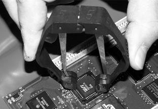
Use circuit chip extraction tool P/N 950-032. See Figure7-68
Failure to use an approved circuit chip removal tool can result in damage to the chip or socket. Use correct electrostatic discharge precautions. See “Static Precautions” on page2-8.

3.Insert the prongs of the extraction tool into the holes identified in the previous step. Hold the tool perpendicular (straight up) to the socket. See Figure7-70
Removal
1.Turn the key switch OFF and disconnect the battery connector.
2.Look at the circuit chip’s socket on the circuit board. Of the four slots in the corners of the socket, two diagonally opposite slots open into the chip cavity. These holes receive the prongs of the removal tool.
4.Gently but firmly squeeze the jaws of the tool together. The prongs retract, lifting and loosening the chip from its socket. Do not rock or pull on the chip to release it.
Chip Installation
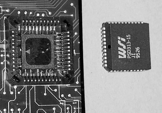
1.Inspect the chip to make sure there are no bent, broken, or missing pins or other signs of physical damage. See Figure7-71 .
Publication: 1089040, Issued: 08 Apr 2016
Guidance Manager Firmware ReplacementElectrical Components 7-56
Model 9600/9700 Swing-Reach ® Lift Truck
Section 7.Component Procedures
2.Notice the beveled corner and the arrow in the chip socket. Notice the beveled corner and the dot on the beveled edge of the chip. See Figure7-69 on page7-56


3.Orient the chip so the dot on the chip matches the arrow on the socket and the beveled corner of the chip matches the beveled corner of the socket.
4.With your thumb, gently press the chip into the socket. Make sure it is completely seated on all four edges. See Figure7-72 and Figure7-73 .

Publication: 1089040, Issued: 08 Apr 2016
Section 7.Component Procedures
Model 9600/9700 Swing-Reach ® Lift Truck
Mini-Mast Height Proximity SensorElectrical Components
Mini-Mast Height Proximity Sensor
Procedures for removing and installing the mini-mast height sensor depend on the height of the mini-mast. If you have the 118 in. (300cm) mini-mast, the sensor is accessible by removing a section of the height sensing rail. If you have the 84 in. (213 cm) mini-mast, you must partially disassemble the load handler and remove it from the mast. Both procedures are described below.
Removal [118 in./300 cm mini-mast]
1.Remove the load handler turret cover and traverse motor cover.
2.Turn the key switch OFF and disconnect the battery connector.
3.Working from a ladder or work platform, remove the top-most section of the mini-mast height sensing rail. See Figure7-74

4.Reconnect the battery connector and turn the key switch ON.
5.Elevate the load handler to position the mini-mast height sensor assembly within the cutout window in the mast, located in front of the traverse hydraulic motor. See Figure7-75 .
Mounting Screws
6.Turn the key switch OFF and disconnect the battery connector.

7.Working from a ladder or work platform, remove the height sensor cable harness from the height manage r card at connector JP2 under the turret. Remove cable ties on the cable harness, noting their location for reinstallation. Using the appropriate tool, remove the pins from the J2 connector. Attach a 6 ft. (2 m) length of 18 gauge wire to these pins and tape them together securely to aid in routing the new harness cable. Secure the other end of the wire to the turret.
8.Remove the three bolts holding the sensor bracket to the mini-mast. See Figure7-79 on page7-61 for a clear view of the location. Pull the wiring harness through the metal tubing until the attached wire appears. Remove wire and tape it to the replacement sensor assembly cable.
9.Remove the fender washer securing the sensor housing in the mounting bracket. Remove the sensor housing and wave spring. Remove the sensor from the housing. See Figure7-80 on page7-61 and Figure7-81 on page7-62 .
Publication: 1089040, Issued: 08 Apr 2016


