5 minute read
Section 7.Component Procedures
Model 9600/9700 Swing-Reach ® Lift Truck
Wiring and Harness ConnectorsElectrical Components
Wiring and Harness Connectors
General Repair Procedures
See “Electrical Troubleshooting” on page5-2
Whenever working on the lift truck, use care around wiring harnesses.
•Carefully connect and disconnect all connections.
•Do not pry connectors apart with unspecified tools.
There should be a wire marker at each termination. If the marker is missing or unreadable, remark the wire to allow easier identification.
NOTE: It is normal to find unused connectors for uninstalled options that have had heat shrink applied over them and have been strapped to the harness.
Repair
Use correct electrostatic discharge precautions. See “Static Precautions” on page2-8.
When pulling a wire out through a bundle, cut off the pin or socket so it does not snag. When replacing wires, tape or solder one end of a new wire to one end of the failed wire. Pull the new wire into the bundle. Make sure to disconnect the old wire from the new wire.
In other cases, it is easier to secure a new wire to the outside of the existing wire bundle with cable ties of an appropriate size. Leave the failed wire in the bundle, or pull it by one end to remove it from the bundle.
When replacing wires, follow these guidelines:
•Use the appropriate tools to remove and insert terminations at each connector.
•Remove damaged terminations and discard. Never reuse a termination from a wire.
•Do not cut away a terminal lug and reuse the wire strands that were crimped into the original lug.
•When stripping wire, use new wire strands for new terminations. Make sure to use a new wire with extra length to allow for cutting and stripping of the ends to install new terminations.
•Use a new wire that is the same gauge (typically gauge 18 AWG), size, type, and color as the wire it is replacing.
•Use a hand stripper capable of stripping by wire gauge number. Use care not to nick or cut any of the wire strands. Discard and replace a wire with damaged strands. Insert the wire strands the correct length into termination before crimping.
Soldering Procedures
To prevent damage from excessive heat when soldering small components in assemblies, follow these guidelines:
•Make sure the soldering tip is clean. A dirty tip does not transfer heat well and encourages long dwell time and greater pressure. Apply light pressure on the terminal.
•Flux: rosin base
•Solder: 60/40 rosin core or equivalent
•Solder Iron: 15-25 watt “pencil-type” maximum
•Tip Size: 3 mm (0.118 in.) diameter x 30 mm (1.182 in.) long screwdriver tip. Make sure the tip is clean.
•After soldering, clean the terminals with a brush dampened with an alcohol-based cleaner (P/N990-600/FOF). Do not allow any cleaner to seep into the switches or potentiometers, or contact contamination may occur.
Publication: 1089040, Issued: 08 Apr 2016
Model 9600/9700 Swing-Reach ® Lift Truck
Section 7.Component Procedures
Electrical Components Wiring and Harness Connectors
Molex Connectors
For pin orientation of Molex connectors, see Figure5-1 on page5-7. Molex connectors have pins with locking ears that engage ridges in the plastic connector body. To remove a pin from a Molex connector, press these locking ears far enough to clear the ridge in the connector. See Figure7-49
Pin Extraction
To remove a pin from a Molex connector, use pin extraction tool P/N 950-026.
1.Insert the extraction tool over the pin and push all the way into the connector. This releases the locking ears on the pin.
2.Pull the wire and pin from the connector.
Pin Insertion
To insert a pin into a Molex connector, insert the pin into the back side of the connector and push the wire all the way in until it clicks. The locking ears have now engaged the connector. See Figure7-50
Publication: 1089040, Issued: 08 Apr 2016 7-43
Section 7.Component Procedures
Model 9600/9700 Swing-Reach ® Lift Truck
Wiring and Harness ConnectorsElectrical Components
AMP Water-Resistant Connectors
AMP connectors provide water-resistant connection by the use of seals between wires and connectors and between the mating connector halves. See Figure7-51.
Wire Seal
Pin Contact
Contact Cavity
Interface Seal
Sealing Plug
To maintain the integrity of water-resistant seals, use the following procedures when working with AMP connectors.
Pin Extraction
To aid in separating AMP connectors, use unlatching tool P/N950-042. To remove a pin from an AMP connector, use pin extraction tool P/N950-009.
1.While holding the wire seal, push the selected wire forward, then insert the extraction tool into the contact socket. See Figure7-52

Pin Housing
Jack Housing
Wire Seal
Extraction Tool
7-44
2.Pull the wire gently until you feel the contact locking lances disengage.
3.Holding the wire seal and connector housing together, rotate the wire while pulling it through the wire seal. This prevents damage to the seal. See Figure7-53 .
Publication: 1089040, Issued: 08 Apr 2016
Model 9600/9700 Swing-Reach ® Lift Truck
Section 7.Component Procedures
Electrical Components Wiring and Harness Connectors
Rotate
Pin Insertion
1.Make sure the connector has a wire seal attached to the connector back. See Figure7-54 .


Seals
1.Use a wire seal at the back (wire end) of each connector half. See Figure7-54

2.Plug unused pin positions with sealing plugs. See Figure7-56
Figure 7-56.Sealing Plug
Sealing Plug
2.If re-inserting a wire previously removed, check the pin contact locking lances to make sure they are extended to their original position.
3.Grasp the wire close behind the contact insulation barrel and push the wire straight through the wire seal into the socket until it clicks. Pull back gently to make sure the contact is locked in place.
See Figure7-55
3.Align the split tapered end of the sealing plug with the unused opening in the wire seal. Push the plug through the wire seal into the connector until it snaps into position.
4.Remove sealing plugs by pulling with needle-nose pliers while grasping the wire seal and connector.
5.Use an interface seal between pin and jack halves of the connector. To prevent damage to the seal, use the matching connector cap to slide the interface seal over the contact silos on the pin housing. See Figure7-57
Publication: 1089040, Issued: 08 Apr 2016 7-45
Section 7.Component Procedures
Model 9600/9700 Swing-Reach ® Lift Truck
6.When mating connectors, make sure polarized silos are correctly oriented. Push pin and jack halves of the connector together until locking latches engage. See Figure7-58 .


Publication: 1089040, Issued: 08 Apr 2016
Wiring and Harness ConnectorsElectrical Components 7-46
Model 9600/9700 Swing-Reach ® Lift Truck
Section 7.Component Procedures
Electrical Components Wiring and Harness Connectors
AMP Harness/Power Amp Connector

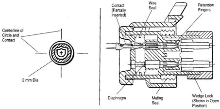
Connector Components
Disassembly (Contact Removal)
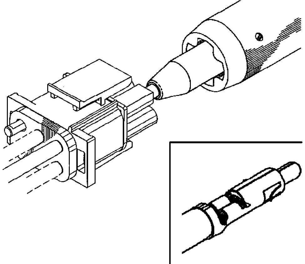
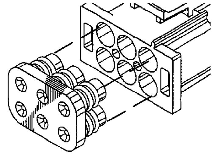
1.Insert a 4.8 mm screwdriver blade between the mating seal and one of the red wedge lock tabs. See Figure7-60.
2.Pry open the wedge lock to the open position.
3.While rotating the wire back and forth over a half turn (1/4 turn in each direction), gently pull the wire until the contact is removed.
Contact Insertion
The axial concentricity of the crimped contact shall fall into an area defined by a 2 mm diameter cylinder whose center is the centerline of the contact front end. See Figure7-61.
Assembly
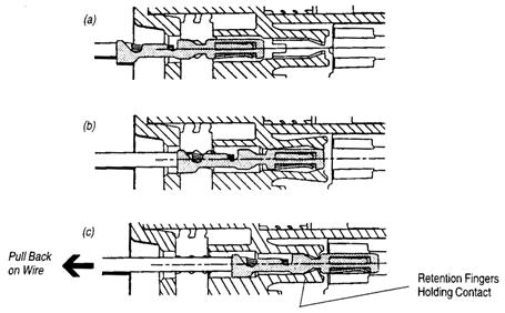
Make sure the wedge lock is open.
1.To insert a contact, push it straight into the appropriate circuit cavity as far as it will go. See Figure 7-61 (a) and (b).
2.Pull back on the contact wire with a force of 1 or 2 lb. to make sure the retention fingers are holding the contact. See Figure 7-61 (c).
Publication: 1089040, Issued: 08 Apr 2016 7-47
Section 7.Component Procedures
Model 9600/9700 Swing-Reach ® Lift Truck
Wiring and Harness ConnectorsElectrical Components

3.After all contacts are inserted, close the wedge lock to its locked position. Release the locking latches by squeezing them inward. See Figure7-62.

Be very careful when putting the wedge lock in the locked position. Forcing the wedge lock can cause damage to the connector. Make sure the wedge lock is aligned correctly. If resistance is felt, slightly adjust the wedge lock until it slides in freely.
4.Slide the wedge lock into the housing until it is flush with the housing. See Figure7-63.
7-48
Publication: 1089040, Issued: 08 Apr 2016


