

Your decision to purchase the Mustang compact excavator was a good one. We are sure that your decision was carefully considered and that you are looking forward to many years of reliable performance from the machine.
Mustang Manufacturing Co., Inc. has invested much time and effort in developing its lines of equipment. The machine you have purchased is built with a great deal of pride, and designed to provide long life, efficient operation, durability and dependability.
Modern machinery has become more sophisticated and, with that in mind, Mustang Manufacturing Co., Inc. asks that you read and COMPLETELY understand the contents of this manual and become familiar with the new machine, BEFORE attempting to service it.
This manual was developed specifically for the machine you have purchased. The information within is for your assistance in preparing, adjusting, maintaining and servicing the machine. More importantly, this manual provides a service plan for safe and proper servicing of the machine. Refer to the Table of Contents for an outline (by chapters) of this manual. Use the Index, located at the back of this manual, for specific chapter and topic/page number references.
If the machine was purchased "used," or if the owner's address has changed, please provide your Mustang dealer or Mustang Manufacturing Co., Inc. with the owner's name and current address, along with the machine model and serial number. This will allow the registered owner information to be updated, so that the owner can be notified directly in case of an important product issue, such as a safety update program.
“Right” and “left” are determined from the position of sitting in the operator’s seat, facing forward.
Mustang Manufacturing Co., Inc. reserves the right to make changes or improvements in the design or construction of any part without incurring the obligation to install such changes on any unit previously delivered.
Throughout this manual information is provided that is introduced by the word NOTE or IMPORTANT. Be sure to read carefully and comply with the message or directive given. Following this information will improve your maintenance efficiency, help you to avoid costly breakdowns or unnecessary damage and extend the machine's life.
Operational safety and readiness of the machine depends partially on maintenance and service. This is why regular maintenance and service work is absolutely necessary. Extensive maintenance and repair work must always be carried out by a qualified technician with appropriate training. Insist on using Mustang original service parts when carrying out maintenance and repair work. This ensures operational safety and readiness of the machine, and maintains its value.
Our wide dealership network stands ready to provide any assistance required, including genuine Mustang service parts. All parts should be obtained from or ordered through your Mustang dealer. Give complete information about the part as well as the model number and serial number of your machine. Record numbers, in the spaces provided, as a handy record for quick reference.
Purchased from:___________________________________
Date of Purchase: __________________________________
Model No.: _______________________________________
Serial No.:________________________________________
1.2Serialnumberlocations,typedecalsandcomponentnumbers
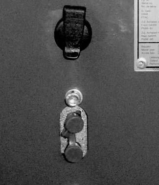
Serialnumber
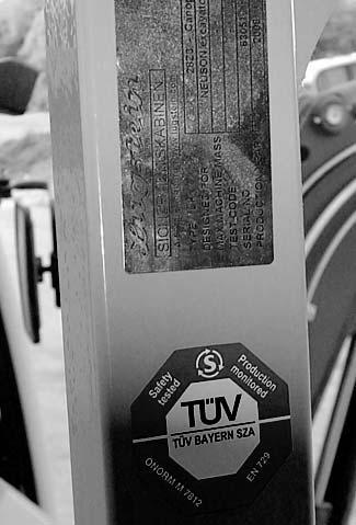
The serial number is stamped on the machine chassis. It is also located on the type label. The type label is located at the front left on the machine frame (at cab level)
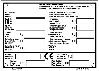
Type label information
Model:2803ZT
Serial no.:AG 00000
Model year:2008
Output:15.2 kW
Dead Weight:2670 kg
Max. payload:___________
Gross axle weight rating:___________
Other information – see Specifications on page 2-1
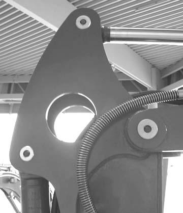
Cabnumber
The type label (arrow) is located on the chassis of the cab, at the upper left beside the door.

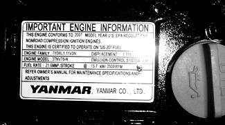
Enginenumber
The type label (arrow) is located on the cylinder-head cover (engine).
Example: Yanmar 46557
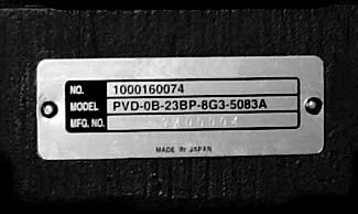
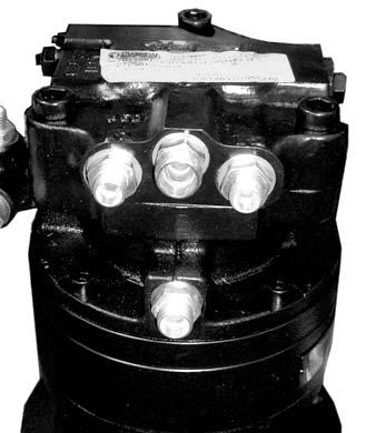
Hydraulicpumpnumber
The type label (arrow) is located on the hydraulic pump housing.
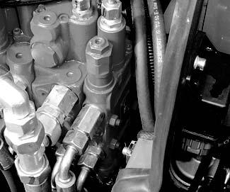
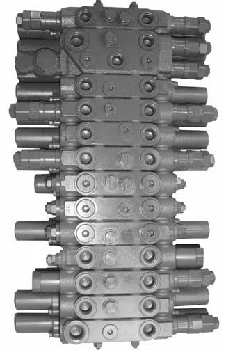
Mainvalveblocknumber
The type label (arrow) is located on the lower side of the main valve block.
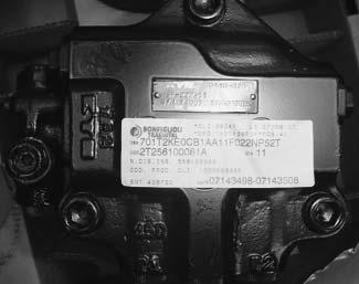
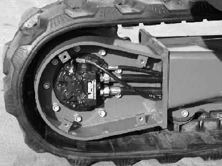
Traveldrivenumber
The type label (arrow) is located on the travel drive.
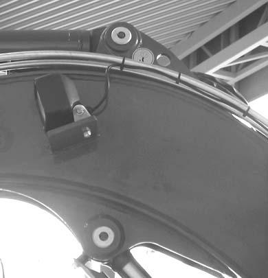
Swivelunitnumber
The type label (arrow) is located on top of the swivel unit.
1.3Designated uses and exemption from liability
• The machine is intended for:
- Excavating soil, gravel, coarse gravel, ballast or rubble.
- Working with the attachments mentioned.
• Every other use and attachment is not designated for this machine. Mustang Manufacturing Co., Inc. will not be liable for damage resulting from any other use or attachment. The user alone will bear the risk.
• Follow the instructions in the Operator’s Manual, and also accident prevention regulations, safety and occupational regulations, and machine and traffic regulations. Mustang Manufacturing Co., Inc. is not liable for damage resulting from the failure to follow these regulations.
• You can damage the machine by modifying it with parts, equipment, attachments and optional equipment not authorized by Mustang Manufacturing Co., Inc. Mustang Manufacturing Co., Inc. is not liable for damage resulting from unauthorized modifications.
• Mustang Manufacturing Co., Inc. is not liable for personal injury and/or damage to property caused by failure to properly:
- operate,
- transport,
- service and maintain,
- and repair the machine as instructed in this manual and the Operator’s Manual.
• Read and understand the Operator’s Manual before starting, servicing, or repairing the machine. Follow the safety instructions.
• The machine may not be used for transportation on public roads.
• In applications with lifting gear, only use the machine according to its designated use.
1.4Abbreviations/symbols
Abbreviations/symbols
• This symbol stands for a list
- Subdivision within lists or an activity. Follow the steps in the sequence presented.
☞ This symbol requires you to carry out the activity described.
➥ Description of the effects or results of an activity.
n. s. = not shown
“Option” = optional equipment (indicated whenever controls or other components of the machine are installed as an option)
A combination of digits, or a combination of digits and letters, e.g. 40/18 or 40/ A, is used for identifying figure elements. For example:
• Figure no. 40/ element no. 18, or position A in figure no. 40.
• Figures carry no numbers if they are placed to the left of the text.
1.5Identificationofwarningsanddangers
The following signal words are used throughout this manual and on decals on the machine to warn of potentially hazardous conditions.
DANGER!/WARNING!/CAUTION!
Failure to follow the instructions identified by this symbol may result in personal injury or death to the operator or other persons.
☞ Measures for avoiding the hazard.
IMPORTANT!
Failure to follow the instructions identified by this symbol may result in damage to the machine.
☞ Measures for avoiding damage to the machine.
NOTE: Contains instructions to help use the machine more efficiently.
Environment!
Failure to follow the instructions identified by this symbol may result in damage to the environment. The environment can be damaged if hazardous material (e.g., waste oil) is not properly used or disposed.
1.6Machineoverview


1.8Cablegend
Pos.Description
1Boom swivel pedal
2Drive pedal (left)
3Drive lever (left)
4Drive lever (right)
5Drive pedal (right)
6Lever – horizontal seat adjustment
7Auxiliary hydraulics pedal
8Instrument Cluster
9Pre-heating start switch
10Joystick (right)
11Joystick base (right)
12Dozer blade lever
13Console switch panel
14Cab switch panel
15Cigarette lighter
16Radio (option)
17Cup holder
18Air vents
19Cab bearing
20Changeover valve for SAE/ISO controls (option)
21Seat (backrest adjustment)
22Seat belt (lock)
23Armrest (left)
24Armrest on the right (not shown)
25Throttle
26Joystick base
27Joystick
28Document storage (underneath the seat console)
29Seat
1.10Instrumentpanellegend
Pos.Description
30Indicator (yellow) – cold starter
31Indicator (red) – hydraulic oil filter
32Indicator (red) – alternator charge function
33Indicator (red) – engine oil pressure
34Indicator (red) – coolant temperature
35Indicator (red) – safe load indicator (option)
36Fuel level indicator
37Hour meter
38High speed switch
39Fan switch
40Safe load indicator (option)
41Hydraulic quickhitch switch (option)
42Proportional control status indicator (option)
43Washer switch
44Work light switch
45Roof lights switch (option)
46Rotating beacon switch (option)
47Air filter indicator
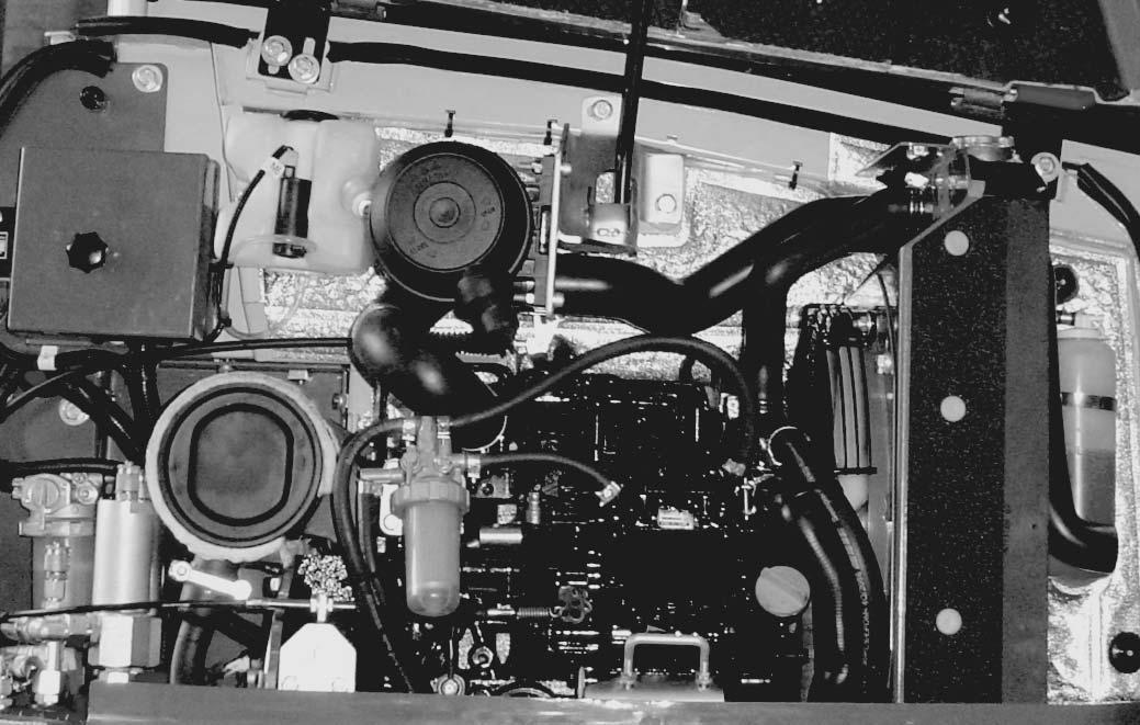
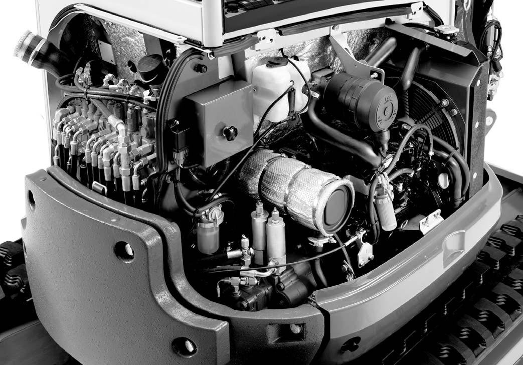
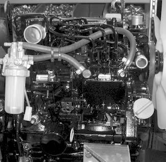
1.11Enginecompartmentoverview

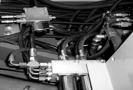
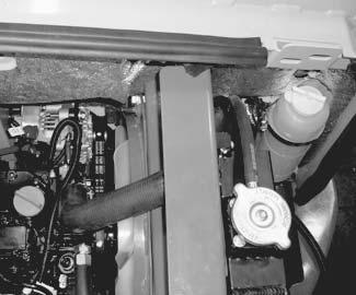
1.13Valvecompartment
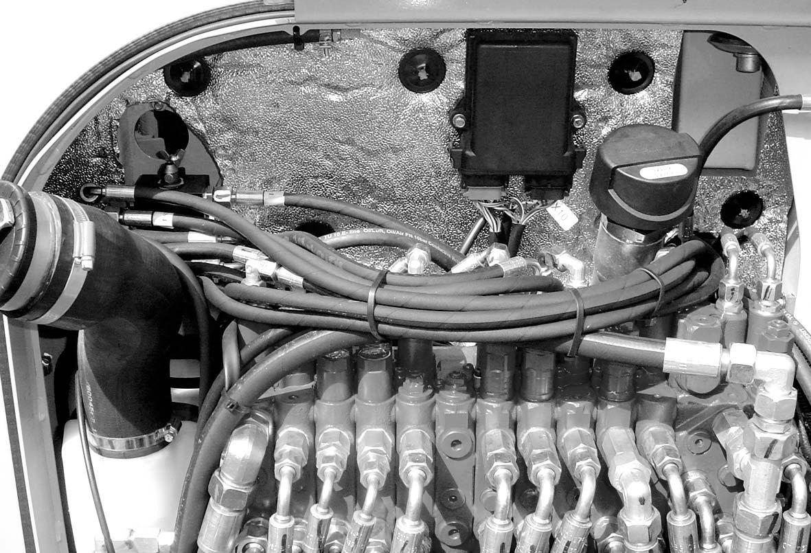
1.14Overviewofopenengineandvalvecompartment
2Specifications
2.1Chassis
2.2Engine
Sturdy steel sheet chassis, rubber-mounted engine.
Engine
Make Yanmar diesel engine
Type
Design
3TNV76-NNS
Water–cooled 4–stroke diesel engine
No. of cylinders 3
Fuel injection system
Indirect injection
Aspiration Natural aspiration
Cooling system
Lubrication
Direction
Water-cooled/aspirating fan
Average engine droop
About 60 rpm; after turning off a warm engine boom, dipper and bucket as far as it will go
2.3Hydraulicsystem
Auxiliaryhydraulicsoilflow
IMPORTANT!
Output indications for auxiliary hydraulics with unpressurized hammer return line.
V, 40 A
V, 1.4 hp (1.1
V; 44 Ah; 680 CCA
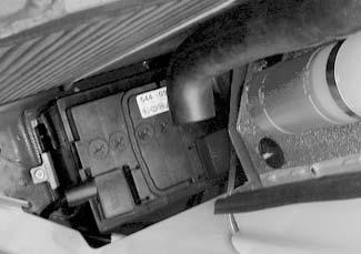
Fusebox
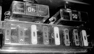
The fuse box is located in the engine compartment.
Fuseno.Ratedcurrent(A)Protectedcircuit
F310 AIndicators, cutoff solenoid, relays
F410 ABoom working light
F515 ACab working light
F610 AValves, horn
F715 AHeating, air conditioning
F810 AWiper, interior light
F910 ARotating beacon, radio, cigarette lighter
F1015 ASocket
Fuseno.Ratedcurrent(A)Protectedcircuit
F140 AStart, preheat, cutoff solenoid
F250 AIgnition lock
Relayno.Protectedcircuit
K6Pre-heating time lag relay
K7Starting relay
K8Cutoff solenoid time lag relay


K9Pick-up contact cutoff solenoid relay
2.7Noiselevels
Soundpowerlevel
Sound power level (LWA)93 dB (A)
Sound pressure level (LPA) at the operator’s ear ≤77 dB (A)
IMPORTANT!
Measurement of sound power level according to EC Directive 2000/14/EC. Noise level at the operator’s ear measured according to EC Directives 84/532/EEC, 89/ 514/EEC and 95/27/EEC.
Measurements carried out on asphalt surface.
2.8Vibration
Vibration
Effective acceleration value for the upper extremities of the body *
Effective acceleration value for the body *
2.9Coolantcompoundtable
< Trigger value
< Trigger value
Outsidetemperature Coolant:HalvolineXLC(basedonethyleneglycol) WaterAnti-corrosion agentAntifreeze agent
2.10Model-specifictighteningtorques
Tighteninggradesandtorquesinlb.-ft.(Nm)
*All connections with an * must be glued with Loctite S2420 or VaryBond 12-43.
2.11Generaltighteningtorques
Tighteningtorquesforhydraulicscrewconnections(dryassembly)
Galvanized and dry surface (O-ring slightly oiled). Torque tolerance: -10% Values determined empirically and to be applied as approximate figures.
Metrichosefittingsforhydraulicapplications(heavyexecution,DKOL)
NominaløOuterøThreadWidthacross
Galvanized and dry surface (O-ring slightly oiled). Torque tolerance: -10% Values determined empirically and to be applied as approximate figures.
Screwconnectionswithvarioussealsforhydraulicapplications(lightapplication)
Screw connections with various seals for hydraulic applications (heavy application)
Torque tolerance: – 10%; counter material: steel/aluminium
Tighteningtorquesforhigh-resistancescrewconnections
Withcoarse-pitchthread,torquesinlb.-ft.(Nm)
2.12Dimensions
2.13Liftcapacitytable
Maximum admissible load on extended dipper arm
AReach from live ring center
BLoad hook height
*Lift capacity limited by hydraulics
All table values are in lbs. (kg) and for a machine in a horizontal position on firm ground without bucket.
Dozer blade in driving direction
Dozer blade 90° to driving direction
If equipped with a bucket or other attachments, lift capacity or tilt load is reduced by bucket or attachment weight.
Calculation basis: According to ISO 10567.
The track excavator's lift capacity is restricted by the settings of the pressure limiting valves and the hydraulic system's stabilizing features. Neither 75% of the static tilt load nor 87% of the hydraulic lift capacity is exceeded.
2.14Liftcapacitytablewithoptionalcounterweight
Maximum admissible load on extended dipper arm
AReach from live ring center
BLoad hook height
*Lift capacity limited by hydraulics
All table values are in lbs. (kg) and for a machine in a horizontal position on firm ground without bucket.
Dozer blade in driving direction
Dozer blade 90° to driving direction
If equipped with a bucket or other attachments, lift capacity or tilt load is reduced by bucket or attachment weight.
Calculation basis: According to ISO 10567.
The track excavator's lift capacity is restricted by the settings of the pressure limiting valves and the hydraulic system's stabilizing features. Neither 75% of the static tilt load nor 87% of the hydraulic lift capacity is exceeded.
2.15Bucketgeometry
EPin diameter1-1/2 in. (40 mm)
FBucket dipper width5-1/2 in. (140 mm)
LPin distance to bucket mount7 in. (180 mm)
Bucket Dipper arm
Bucket
Maintenance
3Maintenance
3.1Fluidsandlubricants
RadiatorCoolant
96 (EU) ISO 8217 DMX (International) BS 2869 – A1 (GB) Depending on outside temperatures
BS 2869 – A2 (GB)
Soft water + antifreeze ASTM D4985
Distilled water + antifreeze ASTM D4985
Washer systemCleaning agentWater + antifreeze
1.The capacities indicated are approximate values; the oil level check alone is relevant for the correct oil level. Capacities indicated are not system fills.
2.According to DIN 51502; API CD, CF, CF-4, CI-4; ACEA E3, E4, E5.
3.Hypoid gearbox oil based on basic mineral oil (according to DIN 51502), (API GL-4, GL5).
4.According to DIN 51524 section 3.
Summer or winter diesel fuel
Year-round About 4.75 qts. (4.5 L)
Year-round1.2 qts. (1.2 L)
5.Biodegradable hydraulic oil based on saturated synthetic esters with an iodine value of < 10 g/mg, according to DIN 51524, section 3, HVLP, HEES.
6.KF2K-25 according to DIN 51502 multipurpose lithium grease with MoS² additive.
7.KP2N-20 according to DIN 51502 EP multipurpose calcium sulphonate complex grease.
8.KF2K-25 according to DIN 51502 multipurpose lithium grease with MoS² additive.
9.Standard acid-proof grease.
Oil grades for the diesel engine, depending on temperature.
Additionaloilchangeandfilterreplacement(hydraulics)
CAUTION!
An additional oil change and filter replacement may be required depending on how the machine is used. Failure to observe these replacement intervals can cause damage to hydraulic components.
☞ Observe the following intervals
IMPORTANT!
Please refer to the maintenance schedule on page 3-5 for additional maintenance work.
3.2Maintenancelabel
Explanationofsymbolsonthemaintenancelabel
SymbolAssemblyExplanation
GeneralVisual check
GeneralGrease instructions
Fuel systemDrain condensation water
Fuel systemReplace the fuel filter, clean the fuel pre–filter
RadiatorCheck the coolant level
RadiatorDrain and fill coolant
EngineCheck valve tip clearance. Adjust if necessary
EngineCheck the engine oil level
EngineChange engine oil
EngineReplace the oil filter
EngineCheck V-belt tension
Travel driveChange oil
Travel driveCheck oil level
UndercarriageCheck track tension
Hydraulic systemCheck oil level
Hydraulic systemChange hydraulic oil
Hydraulic systemReplace the hydraulic oil filter, replace the breather filter
3.3Maintenanceschedule
1.After emptying the tank, water must be removed and air must be purged from the fuel system before use. See “Fuel shut-off valve and water separator” on page3-11 and “Bleeding the fuel system” on page3-10.
2.Check after first 50 hrs. every 500 hrs. thereafter.
Check,cleanorinspect
Fluidandfilterchanges
3.4Servicepackage
3.5Introduction
Operational readiness and the service life of the machines depends heavily upon maintenance.
It is therefore in the interest of the machine owner to carry out the prescribed maintenance. Before performing service and maintenance, always read, understand and follow the instructions given in:
• The “Safety” chapter in the Operator's Manual.
• The Operator's Manuals of the attachments. Secure open (engine) covers appropriately. Do not open (engine) covers on slopes or in strong wind.
Dirt may be blown away and cause severe injuries when using compressed air. Always wear protective goggles, masks and clothing.
Daily service and maintenance work, and maintenance according to the maintenance plan must be carried out by a specifically trained person. All other maintenance must be carried out by trained and qualified staff only.
The maintenance plans indicate when maintenance described in this manual must be performed (– see Maintenance schedule on page3-5).
3.6Fuelsystem
Specificsafetyinstructions
• When handling fuel, there is a high risk of fire.
• Never work on the fuel system in the vicinity of open flames or sparks.
• DO NOT smoke when working on the fuel system or refueling.
• Before refueling, turn off the engine and remove the ignition key.
• Do not refuel in an enclosed area.
• Wipe up fuel spills immediately.
• Keep the machine clean to reduce the risk of fire.
Refueling
Filler inlet A for the fuel tank is located behind the cab, on the left in driving direction.
DANGER!
All work involving fuel carries an increased Riskoffireandpoisoning.
☞ DO NOT refuel in an enclosed room.
☞ Never complete work on the fuel system in the vicinity of open flames or sparks.
Environment!
When draining fuel from the fuel system, collect the fuel as it drains and dispose of it according to environmental laws.
IMPORTANT!
DO NOT run the fuel tank completely empty. Otherwise, air is drawn into the fuel system. This requires bleeding the fuel system. – see Bleeding the fuel system on page3-10.
IMPORTANT!
Fill up the tank with the correct fuel type at the end of each working day. – see Fluids and lubricants on page3-1 for the correct fuel type. A full tank and the correct fuel prevents condensation from forming in the fuel tank overnight. DO NOT fill the tank completely, but leave some space for the fuel to expand.
StationaryfuelpumpsGeneral
Only refuel from stationary fuel pumps. Fuel from barrels or cans is usually contaminated. Even the smallest particles of dirt can cause:
• Increased engine wear.
• Malfunctions in the fuel system.
• Reduced effectiveness of the fuel filters.
Bleedingthefuelsystem
DANGER!
If draining fuel comes into contact with hot engine parts or the exhaust system, there is an increased Riskofburns.
☞ Never bleed the fuel system if the engine is hot.
Bleed the fuel system in the following cases:
• After removing and replacing the fuel filter, water separator or the fuel lines.
• After running the fuel tank empty.
• After running the engine after it has been out of service for a long period of time.
☞ Bleed the fuel system as follows:
• Fill the fuel tank.
• Turn the ignition key to the first position.
• Wait about five minutes while the fuel system bleeds itself automatically.
• Start the engine.
If the engine runs smoothly for a while, and then stops; or if it does not run smoothly:
• Turn off the engine.
• Bleed the fuel system again as described above.
• Have this checked by authorized service technicians.
Emptyingthefueltank
DANGER!
If draining fuel comes into contact with hot engine parts or the exhaust system, there is an increased
Riskofburns.
☞ Never empty the fuel tank if the engine is hot.
Due to the formation of condensation in the fuel tank, empty the fuel tank every 500 hours as follows:
☞ Place a container with sufficient capacity underneath the drain plug in the chassis.
☞ Open the drain plug to drain the fuel.
☞ Check the fuel tank for contamination and clean if necessary.
☞ Replace the filter according to the maintenance specifications.
☞ Replace the drain plug.
☞ Fill the fuel tank.
☞ Bleed the fuel system – see Bleeding the fuel system on page3-10.
Dieselfuelspecification
Use only high-grade fuels.
GradeUse
• 2-D ASTM D975 – 94 USA
• 1-D ASTM D975 – 94
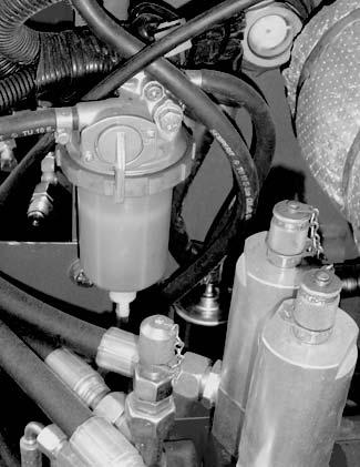
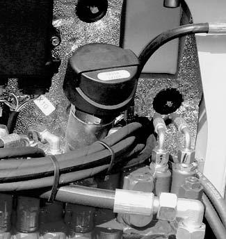
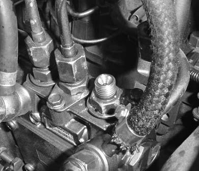
Fuelshut-offvalveandwaterseparator
If water is seen in the water separator bowl, or the indicator ring rises to position C, the separator needs to be drained.

☞ Twist the fuel shut-off valve B to the Off position as shown.
☞ Unscrew plug A.
➥ Wait until the indicator ring returns to the bottom of the water separator.
☞ Tighten plug A
☞ Twist the fuel shut-off valve B to the On position.
Environment!
Collect the water as it drains into a suitable container and dispose of it according to environmental laws.
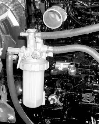
Replacingthefuelfilter
DANGER!
If draining fuel comes into contact with hot engine parts or the exhaust system, there is an increased
Riskofburns.
☞ Never replace the fuel filter if the engine is hot.
Environment!
Use a suitable container to collect the fuel as it drains and dispose of it in an environmentally friendly manner.
☞ Open the engine cover.
☞ Twist the fuel shut-off valve to the Off position.
☞ Unscrew the union nut.
☞ Remove the transparent housing.
☞ Replace the filter insert.
☞ Apply a thin coat of oil or diesel fuel to the housing sealing surface and replace the housing.
☞ Twist the fuel shut-off valve to the On position.
☞ Bleed the fuel system.
– see Bleeding the fuel system on page3-10.
☞ Check the filter for tightness after a short test run.
☞ Dispose of the old filter insert in an environmentally friendly manner.
3.7Enginelubricationsystem
IMPORTANT!
If the engine oil level is too low or if an oil change is overdue, this may cause Enginedamageorlossofoutput.
☞ Have the oil changed by an authorized workshop
– see Maintenance schedule on page3-5.
Checkingtheoillevel
IMPORTANT!
Check the oil level daily. It is recommended to check it before starting the engine. After turning off a warm engine, wait at least five minutes before checking.
• To check the engine oil, the machine must be on a level surface with the engine turned off.

• Turn off the engine and remove the ignition key.
• Fold the control lever base up.
• Let the engine cool down.
• Open the engine cover.
• Clean the area around the oil dipstick with a lint-free cloth.
• Remove the dipstick from the engine.
☞ Wipe it with a lint-free cloth.
☞ Push it back in as far as possible.
☞ Remove the dipstick and read the oil level.
☞ Add oil if required – see Adding engine oil on page3-14
Addingengineoil
IMPORTANT!
Too much or incorrect engine oil may result in engine damage. For this reason:
☞ Do not add engine oil above the MAX mark of oil dipstick 3-6/A
☞ Use only the specified engine oil.
Environment!
Use a suitable container to collect the engine oil as it drains and dispose of it in an environmentally friendly manner.
☞ Proceed as follows:
• Open the engine cover.
• Clean the area around oil filler cap B
• Open filler cap B and raise oil dipstick A slightly to allow any trapped air to escape.
• Add new oil. – see Engine capacities on page2-2. Crankcase capacity is 3.5 qts. (3.3 L). Do Not fill crankcase above the MAX mark on the dipstick.
• Wait about three minutes and Check the oil level – see Checking the oil level on page3-13.
• Add oil if necessary and check the oil level again.
• Replace and tighten the oil filler cap and dipstick.
• Completely remove all oil spills from the engine.
Changingengineoilandfilter
DANGER!
Caution when draining hot engine oil –Riskofburns.
☞ Wear protective gloves.
OIL
☞ Use suitable tools.
Environment!
Use a suitable container to collect the engine oil as it drains and dispose of it in an environmentally friendly manner.
☞ Position the machine on a level surface. Run the engine until it is at operating temperature (oil temperature about 176 °F [80 °C]), then turn off the engine.
☞ Open the engine cover.
☞ Position a waste oil collection container under engine oil pan.
☞ Remove the drain plug from the oil pan and allow the oil to drain into the waste oil collection container.
☞ Dispose of waste engine oil according to environmental laws or take to a recycling center for proper disposal. DO NOT pour waste engine oil onto the ground or down a drain.
☞ Remove the oil filter A, using a filter wrench as necessary.
☞ Clean the filter housing surface. Put a film of clean oil on the filter gasket. Install the new filter with gasket and hand-tighten.
☞ Reinstall the drain plug.
☞ Clean the area around the oil filler cap.
☞ Remove the oil filler cap and raise the oil dipstick slightly to allow any trapped air to escape.
☞ Add new oil. – see Fluids and lubricants on page3-1 for the correct oil type. Crankcase capacity with filter is 3.5 qts. (3.3 L). DO NOT fill crankcase above the MAX mark on the dipstick.
☞ Replace and tighten the oil filler cap.
☞ Push the oil dipstick back in as far as possible.
☞ Wait about three minutes to allow the oil to run into the oil sump and check the oil level according to – see Checking the oil level on page3-13.
☞ Start the engine and let it run for several minutes. Watch the engine oil light on the control panel. The light should turn off after several seconds. If it does not, shut off the engine, determine the cause and fix the problem before restarting the engine.
☞ Stop the engine and check for leaks at the oil filter and oil drain plug.
3.8Coolingsystem
Specificsafetyinstructions
The radiator is located in the engine compartment in front of the engine. The expansion tank for the coolant is also located in the engine compartment, to the right of the radiator.
• Dirt on the radiator fins reduces the radiator’s heat dissipation capacity. To avoid this:
☞ Clean the outside of the radiator at regular intervals. Use oil-free compressed air (29 psi [2 bar] max.) to clean. Maintain a certain distance to the radiator to avoid damage to the radiator fins. – see Maintenance schedule on page3-5.
☞ In dusty or dirty work conditions, clean more frequently than indicated in the maintenance plan.
• Insufficient coolant level reduces the heat dissipation capacity as well and can lead to engine damage. Because of this:
☞ Check the coolant level at regular intervals. – see Maintenance schedule on page35.
☞ If coolant must be added frequently, check the cooling system for leaks and/or contact your dealer.
☞ Never add cold water/coolant if the engine is warm.
☞ After filling the expansion tank:
• Test run the engine.
• Turn off the engine.
• Let the engine cool down.
• Check the coolant level again.
IMPORTANT!
The use of the wrong coolant can destroy the engine and the cooler. Therefore:
• Use the correct type of coolant – see Fluids and lubricants on page3-1.
• Add enough antifreeze compound to the coolant, but never more than 50%. If possible use brand-name antifreeze compounds with anti–corrosion additives.
• Follow the – see Coolant compound table on page2-5.
• DO NOT use cooler cleaning compounds if an antifreeze compound has been added to the coolant. This causes sludge to form, which can damage the engine.
Environment!
Use a suitable container to collect the coolant as it drains and dispose of it according to environmental laws.
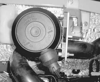
Checking/addingcoolant
DANGER!
Never open the coolant tank and never drain coolant if the engine is warm because the cooling system is under high pressure –
Riskofburns.
☞ Wait at least 15 minutes after turning off the engine.
☞ Wear protective gloves and clothing.
☞ Open filler cap B to the first notch and allow the pressure to escape.
☞ Make sure the coolant temperature is sufficiently low so you can touch the filler cap with your hands.
DANGER!
Antifreeze is flammable and poisonous.
Riskofaccidents.
☞ Keep away from flames.
☞ Avoid eye contact with antifreeze. If antifreeze comes into contact with the eyes, immediately rinse with clean water and seek medical assistance.
Checkingthecoolantlevel
☞ Proceed as follows:

• Park the machine on level ground.
• Turn off the engine.
• Fold up the control lever base.
• Remove the key and keep it with you.
• Let the engine and the coolant cool down.
• Open the engine cover.
• Check the coolant level on the transparent coolant tank A
☞ If the coolant level is below the LOW seam or if there is no coolant at the radiator's filler inlet:

• Fill the expansion reservoir to the FULL line.
NOTE:
Check the coolant level daily before starting the engine.
Drainingcoolant
Addingcoolant
After the engine has cooled down:
☞ Open the radiator filler cap to the first notch and allow the pressure to fully escape.
☞ Remove the filler cap B
☞ Add coolant up to the lower edge of the filler inlet (radiator).
☞ Close filler cap B
☞ Start the engine and let it warm up for about 5 – 10 minutes.
☞ Turn off the engine.
☞ Remove the key and keep it with you.
☞ Let the engine cool down.
☞ Check the coolant level again.
➥ The coolant level must be between the LOWandFULL expansion tank A seams.
☞ If necessary, add coolant and repeat the procedure until the coolant level remains constant.
IMPORTANT!
Service the coolant/antifreeze annually before the cold season sets in.
DANGER!
Never open the coolant tank or drain coolant if the engine is warm, because the cooling system is under high pressure –Riskofburns.
☞ Wait at least 10 minutes after turning off the engine.
☞ Wear protective gloves and clothing.
☞ Open the radiator filler cap B to the first notch and allow the pressure to escape.
After the engine has cooled down:
☞ Release overpressure in the radiator.
☞ Open the radiator filler cap to the first notch and allow the pressure to fully escape.
☞ Open filler cap B
☞ Open the radiator drain plug at the bottom of the radiator and drain the coolant.
☞ Close the drain plug.
➥ Add coolant to the radiator.
–seesection3.1 Fluids and lubricants on page3-1.
–seesection2.9 Coolant compound table on page2-5.
☞ Check the coolant level according to – see Checking the coolant level on page3-17
☞ Close the filler cap.
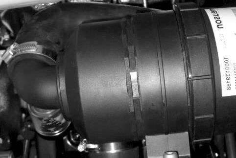
3.9Airfilter
The air filter is located in the engine compartment, on the right side of the machine.

IMPORTANT!
The filter cartridge will be damaged if it is washed or brushed out. To avoid premature engine wear:
☞ DO NOT clean the filter cartridge.
☞ Replace the filter cartridge when the indicator comes on.
☞ Never reuse a damaged filter cartridge.
☞ Ensure cleanliness when replacing the filter cartridge.
Air filter indicator 49 (see page 1-9) monitors the filter cartridge.
☞ Replace outer filter B and inner filter C:
• If the air filter indicator 49 in the round display comes on.
• According to the maintenance schedule.
Replace the air filter according to the maintenance schedule (see page 3-5) or if the fouling indicator A has dropped to “Service.”
IMPORTANT!
For applicationsinanespeciallydustyenvironment, the air filter is fitted with an extra inner filter C. DO NOT clean inner filter C
IMPORTANT!
Filter cartridges degrade prematurely when you use the machine in acidic air for longer periods of time. Acidic air is present, for example, in acid production facilities, steel and aluminium mills, chemical plants and other non-ferrous metal plants.
☞ Replace outer filter B and inner filter C at the latest after 50 hours.
General instructions for air filter maintenance:

• Store filters in their original packaging and in a dry place.
• DO NOT knock the filter against other objects as you install it.
• Check air filter attachments, air intake hoses and air filters for damage, and immediately repair or replace if necessary.
• Check the screws at the induction manifold and the clamps for tightness.
• Check the function of the dust valve, replace if necessary.
Replacingthefilter
• Replace outside filter B as follows:
☞ Turn off the engine.
☞ Remove the key and carry it with you.
☞ Let the engine cool down.
☞ Open the engine cover.
☞ Remove dirt and dust from the air filter and the area around the air filter.
☞ Turn the housing cap A to the left.
☞ Remove the housing cap A
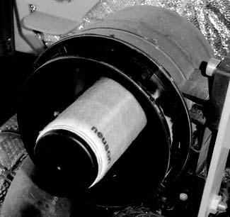
☞ Carefully remove outside filter B with slight turning movements.
☞ Makesure all dirt (dust) inside the upper and lower housing sections (E and A), including dust valve D, has been removed.
☞ Clean the parts with a clean lint-free cloth, DO NOT use compressed air.
☞ Check the air filter cartridges for damage; only install intact filters.
☞ Carefully insert the new outside filter B in the upper housing section E.
☞ Replace the housing cap A and make sure it is properly seated.
☞ Turn the housing cap A to the right to secure it in place.
• Replace inside filter C as follows:
☞ Turn off the engine.
☞ Remove the key and carry it with you.
☞ Let the engine cool down.
☞ Open the engine cover.
☞ Remove dirt and dust from the air filter and the area around the air filter.
☞ Turn the housing cap A to the left.
☞ Remove the housing cap A.
☞ Carefully remove outside filter B with slight turning movements.
☞ Carefully remove inside filter C.
☞ Cover the air supply at the end of the filter with a clean lint-free cloth to prevent dust from entering the engine.
☞ Makesure all dirt (dust) inside the upper and lower housing sections (E and A), including dust valve D, has been removed.
☞ Clean the parts with a clean lint-free cloth, do not use compressed air.
☞ Remove the cloth from the air supply.
☞ Check the air filter cartridges for damage, only install intact filters.
☞ Carefully insert the new inside filter C into the lower housing section A.
☞ Carefully insert the outside filter B into the upper housing section E
☞ Replace housing cap A and make sure it is properly seated.
☞ Turn the housing cap A to the right to secure it in place.
IMPORTANT!
Make sure dust valve D points down once it is installed.
Functionalcheckofthedustvalveonceaweek
☞ Proceed as follows:
• Turn off the engine.
• Fold up the control lever base.
• Remove the key and keep it with you.
• Let the engine cool down.
• Open the engine cover.

• Squeeze the discharge slot of dust valve D
• Remove hardened dust by compressing the upper area of the valve.
☞ Clean the discharge slot if necessary.
3.10V-belt
CheckingV-belttension
DANGER!
Only check, tighten or replace the V-belt when the engine is turned off –Riskofpersonalinjury.
☞ Turn off the engine before carrying out inspection work in the engine compartment.
☞ Disconnect the battery.
☞ Let the engine cool down.
IMPORTANT!
Cracked and stretched V-belts cause engine damage.
☞ Replace the V-belt.
Check the V-belt every 10 hours (or daily if the machine is used for less than 10 hours per day) and tighten if necessary. Tighten new V-belts after approximately 15 minutes of running time.
• Check the V-belt tension as follows:
☞ Turn off the engine.
☞ Fold up the control lever base.
☞ Remove the key and keep it with you.
☞ Allow the engine to cool.
☞ Open the engine cover.
☞ Disconnect the battery using the battery disconnect switch.
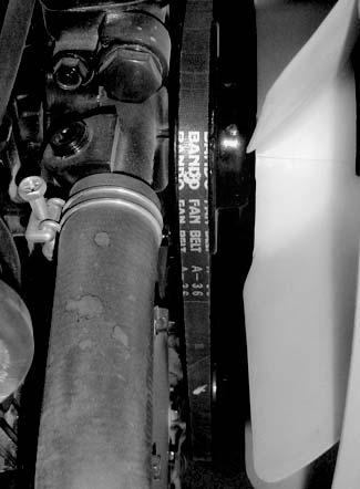
☞ Carefully check V-belt 1 for damage, cracks or cuts.
☞ Replace the V-belt if it touches the base of the V-belt groove or pulley disks.
• If the V-belt is damaged:
☞ Replace the V-belt.
☞ Press with your thumb to check the deflection of the V-belt between the crankshaft disc and the fan wheel C. A new V-belt should have a deflection of 1/4 to 5/16 in. (6 to 8 mm); a used V-belt (after about five minutes running time) should have a deflection of 5/16 to 3/8 in. (7 to 9 mm). This deflection equals about 22 lbf (100 N).
☞ Tighten the V-belt if necessary.
☞ Connect the battery.
TighteningtheV-belt
IMPORTANT!
V-belt over-tension, or misalignment, can damage the V-belt, the V-belt guide, the water pump bearing and the alternator. Do not allow oil, grease, or similar substances to contact the V-belt.
☞ Check V-belt tension – see Checking V-belt tension on page3-22.
• Tighten the V-belt as follows:
☞ Turn off the engine.
☞ Fold up the control lever base.
☞ Remove the key and keep it with you.
☞ Let the engine cool down.
☞ Open the engine cover.
☞ Disconnect the battery using the battery disconnect switch.
☞ Loosen the alternator adjustment bolt 3
☞ Use a suitable tool to push the alternator in the direction of arrow A until the V-belt is correctly tensioned (Fig. 3-10).
☞ Tighten the alternator adjustment bolt 3

☞ Check V-belt tension again and adjust it if necessary.
☞ Connect the battery.
☞ Close the engine cover.
Maintenance
3.11Pressurechecks
General
Pilotcontrolpressurecheck
• Run the machine until it is warm before performing pressure checks. Hydraulic oil temperature:
122° F (50° C) min. (operating temperature)
• Pressure drop is checked by reducing engine speed from full throttle to idle speed while under constant load.
• Set the primary pressure limiting valves (PPLV) at full throttle.
• See “Specifications”. – see Hydraulic system on page2-2 for the pressure settings.
• Ensurethecleanlinessofallmeasuringpointsandports,micromeasuringlines andpressuregaugesthatareconnect edforcheckingpressure,becauseeven theslightesttracesofdirt,e.g.,agrainofsand,caneffectcircuitintegrityand causeleaks.
Checkingpilotcontrolpressure
☞ Connect a pressure gauge to measuring port MP 4 3-12/A.
☞ Move the control lever base (safety switch) to work position.
☞ Check and make a note of the pressure value.
Adjustingpressurereducingvalve4(PRV4)
☞ Adjust the pressure at the pressure reducing valve 4 (PLV4) 3-13/D at the pilot oil supply unit.
☞ Repeat the pilot control pressure check.
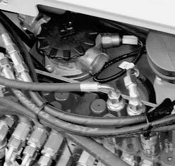
Variable-displacementpumpP1pressurecheck
Hydraulic supply for boom, bucket and right side drive functions.
Checkingtheprimarypressurelimitingvalve1(PPLV1)

☞ Connect a pressure gauge to measuring port MP 1 3-14/1.
☞ Retract the boom cylinder or the bucket cylinder as far as it will go at full throttle.
☞ Check and make a note of the pressure value.
Checkingpressuredrop
☞ At full throttle, retract the boom cylinder or the bucket cylinder as far as it will go.
☞ Quickly reduce engine speed from full throttle to idle and record the pressure drop.
☞ Check and make a note of the pressure value.
➥ The pressure drop should not exceed the specified value by more than 10%. – see Hydraulic system on page2-2 for the pressure settings.

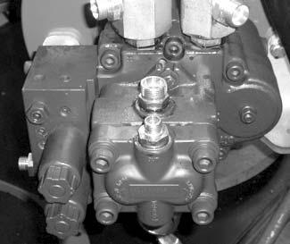
Settingtheprimarypressurelimitingvalve1(PPLV1)
☞ Adjust the pressure at the primary pressure limiting valve (PPLV 1) 3-15/A on the main valve block.
☞ Loosen the locknut on the pressure limiting valve.
☞ Unscrew the pressure limiting valve until you can observe a pressure drop on the pressure gauge.
➥ It may be necessary to loosen the valve seat first.
☞ Adjust the pressure limiting valve and tighten the locknut.
☞ Repeat primary pressure limiting valve 1 and the pressure drop checks.
Alsocheckboomextension,bucketextension/retractionandthe rightsideforward/reversedrivefunctions.
Variable-displacementpumpP2pressurecheck
Hydraulic supply of dipper arm, left side drive and auxiliary hydraulics functions.
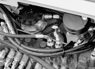
Checkingtheprimarypressurelimitingvalve2(PPLV2)
☞ Connect a pressure gauge to measuring port MP 2 3-16/2
☞ With the engine at full throttle, extend the dipper arm cylinder as far as it will go.
☞ Observe and record the pressure value.
Checkingpressuredrop
☞ With the engine at full throttle, extend the dipper arm cylinder as far as it will go.
☞ Quickly reduce engine speed from full throttle to idle and record the pressure drop.
☞ Observe and record the pressure value.
➥ The pressure drop should not exceed the specified value by more than 10%. – see Hydraulic system on page2-2 for the pressure settings.
Settingtheprimarypressurelimitingvalve2(PPLV2)
☞ Adjust the pressure at the primary pressure limiting valve (PPLV 2) 3-17/B on the main valve block.
☞ Loosen the locknut on the pressure limiting valve.
☞ Unscrew the pressure limiting valve until you observe a pressure drop on the pressure gauge.

➥ It may be necessary to loosen the valve seat first.
☞ Adjust the pressure limiting valve and tighten the locknut.
☞ Repeat the primary pressure limiting valve 2 and the pressure drop checks. Alsocheckdipperarmretractionandtheleftsideforward/reversedrivefunctions.
Checkingtheauxiliaryhydraulicspressure.
NOTE:
Factory specifications for auxiliary hydraulics secondary valves may not be valid because the valves must be adapted to the attachment.
GearpumpP3pressurecheck
Hydraulic supply for the dozer blade, auxiliary hydraulics, boom swivel, upper carriage rotation, optional 3rd control circuit.
Checkingtheprimarypressurelimitingvalve3(PPLV3)
☞ Connect a pressure gauge to measuring port MP 3 3-18/3
☞ With the engine at full throttle, extend the dozer blade cylinder as far as it will go.
☞ Observe and record the pressure value.
Checkingpressuredrop
☞ With the engine at full throttle, extend the dozer blade cylinder as far as it will go.
☞ Quickly reduce engine speed from full throttle to idle and record the pressure drop.
☞ Observe and record the pressure value.
➥ The pressure drop should not exceed the specified value by more than 10%. – see Hydraulic system on page2-2 for the pressure settings.
Settingtheprimarypressurelimitingvalve3(PPLV3)
☞ Adjust the pressure at the primary pressure limiting valve (PPLV 3) 3-19/C on the main valve block.
☞ Loosen the locknut on the pressure limiting valve.
☞ Unscrew the pressure limiting valve until you observe a pressure drop on the pressure gauge.
➥ It may be necessary to loosen the valve seat first.
☞ Adjust the pressure limiting valve and tighten the locknut.
☞ Repeat the primary pressure limiting valve 3 and the pressure drop checks.
Alsocheckdozerbladeretraction,boomsw ivelanduppercarriagerotationfunctions.
Checkingtheauxiliaryhydraulicspressure
NOTE:
Factory specifications for auxiliary hydraulics secondary valves may not be valid because the valves must be adapted to the attachment.
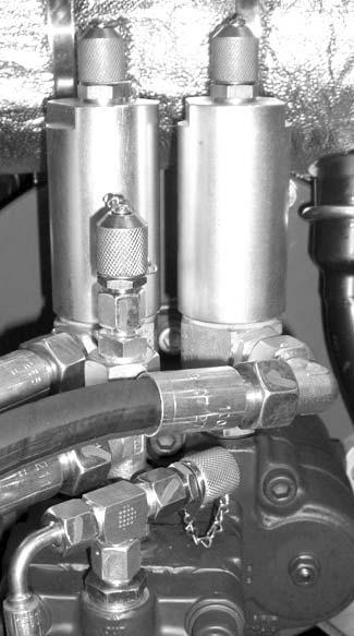
Gearmotorsecondarypressurelimitingvalvepressurecheck
☞ Connect a pressure gauge to measuring port MP 3.
☞ With the engine at idle, place the bucket or the boom against the ground or the dozer blade, or drive against hydraulic resistance.
☞ Observe and record the pressure value.
Adjustingthesecondarypressurelimitingvalveonthegearmotor(atidlingspeed)
☞ With the engine at idle, adjust the pressure at the secondary pressure limiting valve on the gear motor.
☞ Loosen the locknut on the pressure limiting valve.
☞ Unscrew the pressure limiting valve until you observe a pressure drop on the pressure gauge.
➥ It may be necessary to loosen the valve seat first.
☞ Adjust the pressure limiting valve and tighten the locknut.
☞ Repeat the secondary pressure limiting valve check.
Pos.Description

3.4Testreport


3.5Hydraulicsystem
Specificsafetyinstructions
• All lines carrying hydraulic oil must be depressurized prior to any maintenance and repair work. To do this:
☞ Lower all hydraulically controlled attachments to the ground.
☞ Move both joysticks several times in all directions.
☞ Shut off the engine and return the ignition key to the "1" position.
• Fold up the control lever base.
WARNING!
Hydraulic oil escaping under high pressure can penetrate the skin and cause serious injuries. Always consult a doctor immediately, even if the wound appears insignificant, because serious infection could set in.
IMPORTANT!
If the hydraulic oil in the sight glass (Fig. 3-2) is cloudy, this indicates that water or air has entered the hydraulic system. Water or air may cause damage to the hydraulic pumps.

☞ Oil or fuel flowing out of high pressure lines may cause fire or malfunctions, and severe injuries or damage to property. Stop work immediately if loose hydraulic connections or damaged hoses and lines are detected.
☞ Contact your dealer immediately.
• Replace the hose or line if any of the following problems are detected.
☞ Damaged or leaking hydraulic seals.
☞ Worn or torn shells or uncovered reinforcement branches.
☞ Shells expanded in several positions.
☞ Entangled or crushed movable parts.
☞ Debris jammed or stuck in protective layers.
IMPORTANT!
Insufficient, incorrect, or contaminated hydraulic oil presents –Riskofseveredamagetothehydraulicsystem.

☞ Take care to avoid contamination when servicing the machine.
☞ Always add hydraulic oil using a strainer or the return filter.
☞ Only use authorized oils of the same type – see Fluids and lubricants on page 3-1.
☞ Always add hydraulic oil before the level gets too low – see Adding hydraulic oil on page 3-35.
☞ If the hydraulic system is filled with biodegradable oil, then only add biodegradable oil of the same type, and follow the decal on the hydraulic oil tank.
☞ Contact customer service if the hydraulic system filter is contaminated with metal particles. Otherwise, damage may result.
Environment!
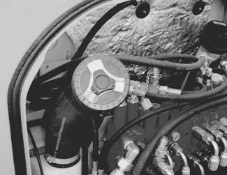
Collect drained hydraulic oil and biodegradable oil in a suitable container. Dispose of drained oil and used filters in an ecologically safe manner. Always contact the relevant authorities or commercial establishments in charge of oil disposal before disposing of biodegradable oil. Checkingthehydraulicoillevel
CAUTION!
Do not add oil if the oil level is above the FULL mark, otherwise the hydraulic system may be damaged and escaping oil may cause serious injuries.
☞ Check the hydraulic oil level each time the machine is put into operation or once a day.

• If the attachment is not positioned as shown:
☞ Start the engine and let it idle.
☞ Retract the bucket and boom cylinders; and lower the boom, the bucket and the dozer blade to the ground.
☞ Turn off the engine.
☞ Proceed as follows:
• Park the machine on level ground.
• Turn off the engine.
• Fold the control lever base up.
• Open the engine cover. Sight glass B is located at the rear right of the excavator below the fuse box.
• Check the oil level on sight glass B.
• The oil level should be at the middle of the sight glass.
•A yellowish color over the entire sight glass indicates overfilling. If the oil level is lower, add hydraulic oil.
The oil level changes according to the machine's operating temperature:
• Normal operation Between 122° and 194° F (50° and 90° C)
IMPORTANT!
In the upper part of the sight glass
Only measure the hydraulic system oil level after the machine reaches operating temperature.
Addinghydraulicoil
Do not add hydraulic oil unless the engine is turned off. Otherwise, hydraulic oil will run out of the filler opening on the hydraulic tank.
☞ Fill up as follows:
• Park the machine on level ground.
• Position the machine as shown in Fig. 3-1
☞ Retract the bucket and boom cylinders; lower the boom, the bucket and the dozer blade to the ground; and set the boom straight (offset cylinder).
• Turn off the engine.
• Fold the control lever base up.
• Clean the area around filler opening with a cloth.
• Open the breather valve.
• Add clean hydraulic oil through the strainer.
• Check the hydraulic oil level on sight glass B
• Add more oil if necessary and check again.
• Close the filler opening.
NOTE:
It is recommended to add oil through the return filter to avoid contaminating the hydraulic oil.
NOTE:
Only change the hydraulic oil when it is warm (about 122° F [50° C]). Retract all hydraulic cylinders before changing the oil.
Changinghydraulicoil
☞ Open the breather filter to release pressure.
☞ Open drain plug 3-5/B and let the oil drain into a container.

☞ Check the hydraulic oil tank for contamination and clean if necessary.
☞ Replace the filter according to the maintenance specifications.
☞ Replace and tighten the drain plug.
☞ Add clean hydraulic oil through the strainer
– see Adding hydraulic oil on page 3-35.
☞ Close the filler opening.
☞ Let the machine run at idle without load for a few minutes.
Monitoringthehydraulicoilreturnfilter
Pressure switch A activates the red indicator 31 on the instrument panel which monitors the return filter.
The control pressure is set at 36 psi (2.5 bar) and cannot be modified. Thefilterelementmustbereplacedbyanauthorizeddealer:
• If indicator 31 comes on when the hydraulic oil is at operating temperature.
• After every 1000 service hours (annually).
In cold weather indicator 31 may come on immediately when the engine is started. This is caused by increased oil viscosity. In this case:
☞ Increase engine speed so that indicator 31 goes out.
CheckinghydraulicpressurelinesSpecificsafetyinstructions
DANGER!
Use caution when checking hydraulic lines, especially when searching for leaks. Hydraulic oil escaping under high pressure can penetrate the skin and cause serious injuries
Riskofpersonalinjury.
☞ Always consult a doctor immediately, even if the wound seems insignificant – otherwise serious infections could set in.
☞ Always:
•Tighten leaking threaded fittings and hose connections only when the system is not under pressure.
•Never weld or solder damaged or leaking pressure lines and threaded connections. Replace damaged parts with new ones.
•Never search for leaks with your bare hands. Wear protective gloves and use paper or wood to check for minor leaks.
•Never use an open flame to inspect hydraulic lines or connections.
•Have damaged flexible lines replaced by an authorized dealer only.
• Leaks and damaged pressure lines must be repaired or replaced immediately by an authorized dealer, not only for safety reasons, but also for environmental reasons.
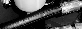
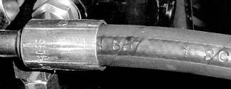
• Replace hydraulic hoses every six years from the date of manufacture, even if they do not appear to be damaged.
The date of manufacture is stamped on the hose at each hose connection. It is recommended that all relevant safety regulations be observed for hydraulic lines, as well as the safety regulations regarding accident prevention and occupational health and safety.
3.6Traveldrive
DANGER!
Immediately after turning off the engine:
•Hot engine components and hydraulic oil may cause burns.
•If the the travel drive circuit is under pressure, the oil or the plug may be blown out at high velocity if the plug is loosened.
Riskofinjuryandscalding.
☞ Wait until the engine has cooled before performing hydraulic system maintenance.
☞ Slowly open the breather valve to release hydraulic pressure.
Checkingtheoillevelandaddingoil
☞ Park the machine on firm, level ground.
☞ Place the machine so that filler plug A is at the top.
☞ Turn off the engine.
☞ Let the engine cool.
☞ Fold the control lever base up.
☞ Unscrew screws A and B with a suitable tool.
☞ A small quantity of oil must flow out of opening B
➥ If the oil does not flow out of opening B, add oil:
☞ Add oil through opening A,
➥ until a small quantity of oil flows out of opening B
☞ Replace and tighten screws A and B
☞ Move the machine a few yards (meters).
☞ Check the oil level again.
➥ If the oil level is not correct:
☞ Repeat the procedure.
Drainingoil
☞ Park the machine on firm, level ground.
☞ Position the machine so that filler plug B is at the bottom.
☞ Turn off the engine.
☞ Let the engine cool.
☞ Fold the control lever base up.
☞ Unscrew screws A and B with a suitable tool.
➥ Oil will drain out of opening B.
Environment!
Collect the oil into a suitable container and dispose of it in an environmentally friendly manner.
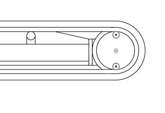
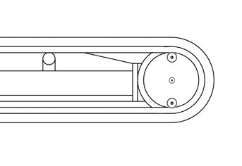
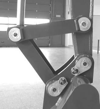
3.7Tracks
• Track wear varies according to work and ground conditions.
☞ We recommend checking track wear and tension daily.
☞ Park the machine on firm, level ground when performing maintenance.
Checkingtracktension
DANGER!
Working under the machine with the tracks off the ground and only supported by the attachment is extremely dangerous
Caution,danger.
☞ Firmly support the machine with chocks or suitable brackets.
Check track tension as follows:
☞ Park the machine on firm, level ground.
☞ Raise the excavator on one side with the boom and the dipper arm as shown in fig. 310.
☞ Slowly and carefully actuate the joysticks.
☞ Turn off the engine.
☞ Remove the key and carry it with you.
☞ Fold the control lever base up.
☞ Use suitable auxiliary means to support the machine.
• Standard play between the sliding block's shoulder and the contact area of the second support roller of the drive pinion is 3/4 — 1 in. (20 — 25 mm).
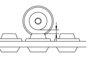
Tracktension
3/4 — 1 in. (20 — 25 mm)
☞ Set the tension if it is not in accordance with the rated value.
DANGER!
The grease fitting may be blown out due to the high grease pressure in the hydraulic cylinder.
Riskofpersonalinjury.
☞ Do not loosen and unscrew the grease fitting by more than one turn.
☞ Loosen no other component except the grease fitting.
☞ Keep your face away from the grease fitting connection.
➥ Contact your dealer if this does not reduce the tension of the rubber sliding block.
IMPORTANT!
Excessive track tension causes severe damage to the cylinder and the track.
☞ Only tighten the tracks up to the prescribed distance.
Tighteningthetracks
☞ Inject grease with the grease gun through grease fitting A.
☞ Check that the tension is correct by starting the engine and letting it idle. Slowly move the machine forward and reverse and turn off the engine again.
☞ Check the track tension again.
➥ If it is not correct:
☞ Adjust again.
☞ If the track is still loose after injecting more grease, replace the track or the seal in the cylinder. Contact your dealer in this case.
Looseningthetracks
DANGER!
educingtension
Draining grease in any way different from the one described below is very risky and may cause damage to the machine or personal injury.
Riskofpersonalinjury.
☞ Place a suitable container underneath to collect the grease.
☞ Slowly open the grease fitting A by one turn to allow the grease to flow out.
➥ The grease flows out of the groove of the grease fitting.
☞ Tighten grease fitting A.
☞ Check that the tension is correct by starting the engine and let it idle. Slowly move the machine forward and reverse and turn the engine off again.
☞ Check the track tension again.
➥ If it is not correct:
☞ Adjust again.
Environment!
Dispose of collected grease in an environmentally friendly manner.
3.8Lubrication
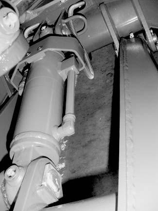
Apply multi-purpose lithium grease with an MoS² additive to all lubrication points indicated. Dozerblade
☞ Apply grease to lubrication points A on the dozer blade cylinder.

☞ Apply grease to lubrication points B (on either side) on the dozer blade.
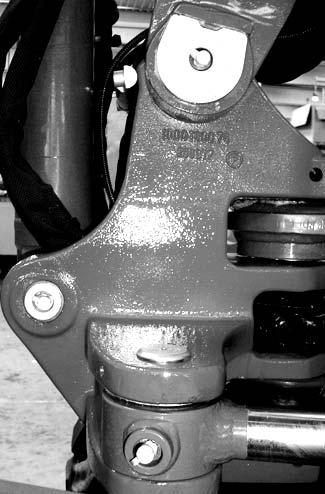
Lubricationpointsontheswivelconsole
☞ Apply grease to lubrication points C of the swivel console.
Boomlubricationpoints
☞ Apply grease to lubrication points D on the boom.
Lubricationpointsonthedipperarm
☞ Apply grease to lubrication points E on the dipper arm.
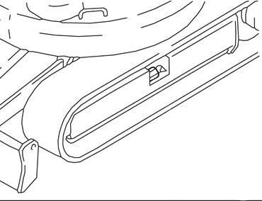
Lubricationstrip
Apply grease to the lubrication strip as follows:
☞ Lubrication point A for live ring ball bearing.
➥ Grease: BP Energrease MP-MG2.
☞ Lubrication point B for the offset cylinder.
IMPORTANT!
Apply grease to lubrication points A and B once a day.
A portable lamp can be connected to the lubrication strip's 12 V connection C
Maintenanceofattachments
IMPORTANT!
Correct maintenance and service is necessary for smooth and continuous operation, and for increased service life of the attachments. Please follow the lubrication and maintenance instructions in the attachment’s Operator's Manual.
3.9Electricalsystem
Specificsafetyinstructions
DANGER!
Battery acid is highly caustic: Riskofacidburn.
When recharging and/or working near the battery:
☞ Always wear goggles and protective clothing with long sleeves. If acid is spilled:
☞ Thoroughly rinse all affected surfaces immediately with plenty of water.
☞ Thoroughly wash any body part touched by the acid immediately with plenty of water and seek medical attention at once.
During charging in particular, but also during normal battery operation, an oxygen-hydrogen mixture is formed in the battery cells –
Riskofexplosion.
☞ Avoid open flame and sparks in the vicinity of the battery, and do not smoke.
☞ Do not jump-start the machine if the battery is frozen or if the acid level is low. The battery may rupture or explode.

☞ Always disconnect the negative cable (–) from the battery before starting repair work on the electrical system.
IMPORTANT!
Always disconnect the negative cable (–) from the battery before starting repair work on the electrical system. Use only 12V power sources. Higher voltages will damage the electrical components.
DO NOT interrupt jump-charging circuits at the battery terminals because of the danger of sparking.
Do not place tools/conductive items on the battery. A short circuit may result. When connecting the battery leads, make sure the poles +/– are not reversed; reversing the poles will damage the electrical components.
• Dispose of used batteries according to environmental regulations.
Regularservice/maintenance
Beforeoperatingthemachine
☞ Check:
– Light system.
– Signaling and warning system.


Weekly
☞ Check:
– Electrical fuses – see Fuse box on page 2-4.
– Cable and ground connections.
– Battery charge condition – see Battery on page 3-46.
– Condition of battery terminals.
Specificcomponentinstructions
Cables,bulbsandfuses
Always follow these instructions:
• Defective electrical system components must always be replaced by an authorized technician. The operator or other persons may change bulbs and fuses.
• Ensure good leads and fuses have good electrical contacts.
• Blown fuses indicate overloading or short circuits. Correct the problem before installing new fuses.
• Only use fuses with the specified load capacity (amperage) – see Fuse box on page 24.
IMPORTANT!
When welding on the machine, remove both cables from the battery and ground the welder to machine frame near the repair area.
Alternator
Always observe the following instructions:
• Only test run the engine with the battery connected.
• When connecting the battery, make sure the poles (+/–) are not reversed.
• Always disconnect the battery before completing welding work or if connecting a quick battery charger.
• Replace defective charge indicators immediately – see Instrument panel legend on page 1-10.
DANGER!
Battery acid is highly caustic: Riskofacidburns.
When recharging and/or working near the battery:
☞ Always wear goggles and protective clothing with long sleeves. If acid is spilled:
☞ Thoroughly rinse all affected surfaces immediately with plenty of water.
☞ Thoroughly wash any part of the body touched by the acid immediately with plenty of water and seek medical attention at once.
During charging in particular, but also during normal battery operation, an oxygen-hydrogen mixture is formed in the battery cells –
Riskofexplosion.
☞ Avoid open flames and sparks in the vicinity of the battery and do not smoke.
☞ Do not attempt to jump-start the machine if the battery is frozen or if the acid level is low. The battery may rupture or explode.
•Replace the battery immediately.
☞ Always disconnect the negative terminal (–) from the battery before starting repair work on the electrical system.
Battery A is located in the engine compartment on the right side.
Battery cables must be clean and tightly secured. Remove any acid or corrosion from the battery and cables using a sodium bicarbonate and water solution. Cover the battery terminals and cable ends with battery-saver grease.
The battery is maintenance-free and requires no other service.
IMPORTANT!
Do not disconnect the battery while the engine is running.
Jump-startingtheengine
IMPORTANT!
When jump-starting from another machine, be sure the second machine is not running while using the unstarted machine’s glow plugs. High voltage spikes from a running machine can burn out the glow plugs.
Be very careful when jump-starting the machine. The booster battery must be 12-volt.
☞ Turn the ignition key on the machine with the discharged battery to the “P” position.
☞ Open the engine cover.
☞ Stop the engine of the machine with the booster battery.
☞ Connect one end of a jumper cable to the positive (+) terminal on the booster battery.
☞ Connect the other end of the same cable to the positive (+) terminal on the battery of the machine with the discharged battery.
☞ Connect one end of the second jumper cable to the negative (–) terminal on the booster battery.
☞ Connect the other end of the same cable to the frame of the machine with the discharged battery.
☞ Allow this discharge battery to charge for a few minutes.
☞ Start the engine of the machine with the discharged battery. Once the engine is running, remove the cable connected to the frame first. Disconnect the other cable from the positive (+) terminal on the battery disconnect switch. Remove the cables from the booster battery last.
IMPORTANT!
DO NOT allow the booster cable ends to touch when removing them from the batteries. Arcs and direct short circuits can cause severe damage to the electrical system.
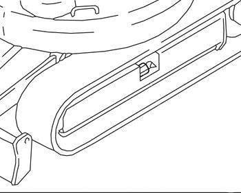
3.10Cab
☞ Check cab fastening hardware B for damage.
IMPORTANT!
Check the cab fastening hardware for tightness. Tighten with a suitable tool if necessary
– see General tightening torques on page 2-6.
Replacingthecabfilter
Fresh/recirculatedairfilter
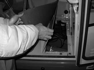
Remove the ventilation grille in the cab to replace the filter. Make sure not to overstretch the cables of the fuse box as you tilt the grille. You can now see the filter mat.
Replacingthefilter:
☞ Remove the hardware securing the ventilation grille in the cab under the seat.
☞ Lift the floor mat and remove the access door in the cab floor.

☞ Remove the ventilation grille.
☞ Remove the existing cab filter from the frame in front of the heating unit.
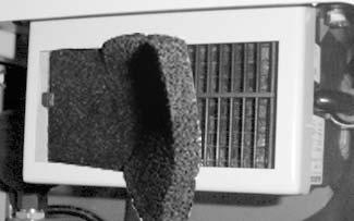

☞ Insert a new cab filter.
☞ Replace the ventilation grille, the access door and the floor mat.
☞ Replace the ventilation grille hardware and tighten securely.
3.11Generalmaintenance Cleaning
Cleaning the machine is divided into three separate areas:
• Inside the cab.
• Machine exterior.
• Engine compartment.
The wrong cleaning equipment and agents can affect the safety of the machine and undermine the health of the persons cleaning the machine.
Generalinstructionsforallareas
Whenusingwashingsolvents
• Ensure adequate room ventilation.
• Wear suitable protective clothing.
• DO NOT use flammable liquids, such as gasoline or diesel fuel.
Whenusingcompressedair
• Work carefully.
• Wear goggles and protective clothing.
• DO NOT aim the compressed air at the skin or at other people.
• DO NOT use compressed air for cleaning your clothing.
Whenusingahigh-pressurecleanerorsteamjet
• Electric components and damping material must be covered and not directly exposed to the jet.
• Cover the vent filter on the hydraulic oil tank, the filler caps for fuel, hydraulic oil, etc.
• Protect the following components from moisture:
• Engine.
• Electric components (alternator, ignition system, etc).
• Control devices and seals.
• Air intake filters, etc.
Whenusingvolatileandeasilyflammableanti–corrosionagentsandsprays:
• Ensure adequate room ventilation.
• DO NOT use unprotected lights or open flames.
• DO NOT smoke.
Insidethecab
Seatbelt
Exteriorofthemachine
Enginecompartment
CAUTION!
Never use high-pressure cleaners, steam jets or high-pressure water to clean inside the cab. Water under high pressure may:
• Penetrate into the electric system and cause short circuits.
• Damage seals and disable controls.
Use any of the following to clean the cab:
• Broom
• Vacuum cleaner
• Damp cloth
• Bristle brush

• Water with mild soap solution
• Only clean the seat belt (DO NOT disconnect the seat belt from the machine) by using a mild soap solution. DO NOT use chemical agents because they may destroy the fabric.
Use any of the following to clean the outside of the cab:
• High-pressure cleaner.
• Steam jet.
WARNING!
Only clean the engine after it is turned off and stopped –Riskofpersonalinjury.
☞ Turn off the engine before cleaning.
IMPORTANT!
When cleaning the engine with a water or steam jet:
☞ The engine must be cold.
☞ DO NOT point the jet directly at electrical sensors such as the oil pressure sender.
Any humidity penetrating these sensors causes them to fail and leads to engine damage.
Screwconnectionsandattachments
All screw connections must be checked regularly for tightness, even if they are not listed in the maintenance schedule.
Tighten loose connections immediately. Contact your dealer if necessary.
Pivotsandhinges
All mechanical pivot points on the machine (e.g., door hinges, joints) and fittings (e.g., door latches) must be lubricated regularly, even if they are not listed in the lubrication schedule.
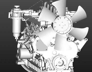
4Engine 4.13TNV76-NNSengineoverview
Airintake
Oilfillerneck Cap
WaterpumpV-belt
Oilpressureswitch
Oildipstick
Fuelinjectionpump
Oilfillerneck
Tighteningbracket
Cylinder-headcover
V-belt
4.3Checkingandadjustingvalvetipclearance
☞ Standard setting of valve tip clearance is possible:
➥ On a cold engine.
☞ Remove the cylinder-head cover.
☞ Turn the engine with a screwdriver (as in 4.7) until the cylinder reaches the top dead center of the compression cycle.
➥ Valve overlapping.
☞ Check valve tip clearance 4-2/A with a feeler gauge.
➥ Valve tip clearance:0 0.005 – 0.009 in. (.15 – 0.25 mm).
☞ Loosen locknut 4-2/C
☞ Set the valve tip clearance on the cylinder by turning set screw 4-2/B.
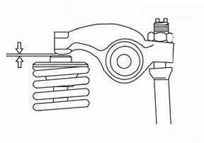
➥ Valve tip clearance:0 0.005 – 0.009 in. (.15 – 0.25 mm).
☞ Tighten locknut 4-2/C – see General tightening torques on page 2-6.
➥ Check the setting again with the feeler gauge.
☞ Repeat the procedure for each cylinder.
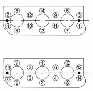
4.4Tighteningorderforcylinderheadbolts
Assembly
☞ Mount the cylinder-head bolts.
➥ Tightening torques:
• 1st pass 19.8–21.3lb.-ft.(26.9–28.9Nm)
• 2nd pass 39.7–42.7lb.-ft.(53.9–57.9Nm)
IMPORTANT!
Follow the correct order when tightening the cylinder-head bolts.
☞ See fig. 4-4.
IMPORTANT! Apply a thin coat of oil to the threads and contact surfaces before mounting.
Removing
IMPORTANT!
Follow the correct order when removing the cylinder-head bolts.
☞ See fig. 4-3.
IMPORTANT!
Always work on the cylinder head on a cold engine.
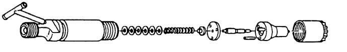
4.5Checkingtheinjectionnozzles
Pressurecheck
☞ Twist the shut-off valve on the fuel filter to the OFF position.
☞ Clean the area around the injection nozzles.
☞ Remove the injection line and the injection nozzle.
☞ Connect the injection nozzle to the high pressure line of the nozzle tester.
☞ Slowly increase pressure until the nozzle ejects fuel and read the pressure on the pressure gauge.
☞ If the injection pressure is too low, replace the spacer in the nozzle with a thicker one. If the pressure is too high, replace the spacer with a thinner one.
➥ Injection pressure: 1711–1856psi(118–128bar)
• Spacer thickness of 0.004 in. (0.1 mm) corresponds to modification by 100 – 142 psi (6.9 – 9.8 bar).
• Check the pressure again.
• Check the injection nozzle for drips after it has ejected fuel.
☞ Create a pressure of about 290 psi (20 bar) below injection pressure and check whether fuel escapes from the nozzle.
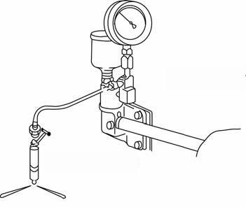
• Install the nozzle.
• Open the shut-off valve on the fuel filter again.
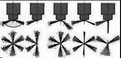
4.6Checkingthenozzlejet
☞ Remove the injection lines and the injection nozzles.
☞ Connect the injection nozzle with the high pressure line of the nozzle tester.
☞ Quickly create pressure until the nozzle ejects fuel (three or four times).
☞ Hold a white sheet of paper about 12 in. (30 cm) away from the nozzle and let the nozzle eject fuel.
☞ The nozzle jet must create a shape on the paper as shown in fig. 4-6.
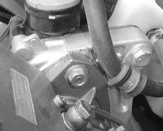
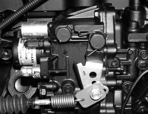
4.7Injectiontime
Checkingandadjustinginjectiontime
• Preparation:
☞ Bleed the fuel system if necessary – see Bleeding the fuel system on page 3-10
☞ Clean the engine.
☞ Mark the position of the fuel injection pump on the engine block.
• Trace the mark with a touch-up applicator.
☞ Move the throttle to work position, and apply current to the cutoff solenoid.
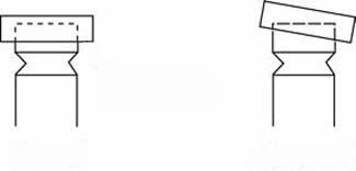
☞ Unscrew only the injection line of the 1st cylinder and bend it a little to the side so that you can see the opening to the fuel injection pump.

NOTE:
To be able to see better, use a section of an injection line (cut at an angle, as shown on the left in fig. 4-7) or a transparent tube (as shown on the right in fig. 4-7) instead of the injection line.
• Measurement:
☞ Remove the cap – see 3TNV76-NNS engine overview on page 4-1.
☞ Rotate the pump in the required direction and stop when fuel starts coming out.
☞ As you do so, carefully watch the opening where the injection line was.
☞ Wipe away the fuel and turn back to about 30° before top dead center of the 1st cylinder.
☞ Repeat the measurement.
☞ Read the mark on the crankshaft (18°). Injection time is set correctly if it corresponds to this value.
☞ If it does not correspond to this value, loosen the fuel injection pump (do not unscrew it completely) and rotate it a little.
➥ Rotated toward the engine: later injection time.
➥ Rotated away from the engine: earlier injection time.
☞ Tighten the fuel injection pump firmly and check injection time again.
☞ Repeat the procedure as required.
IMPORTANT!
Bend the injection lines as you mount them so they are not subject to tension after they are mounted. Bleed the injection lines after they are installed.
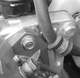
Fuelinjectionpumpreplacement
☞ Clean the engine.
☞ Twist the fuel shut-off valves on the fuel filter and the water separator to the OFF position.
☞ Unscrew the injection lines.
☞ Mark the initial position on the pump and wheel case housing before removing the fuel injection pump.
☞ Remove gear casing cover 4-10/1 of the fuel injection pump.
☞ Turn the engine until the marks on the gears coincide, see Fig. 4-11
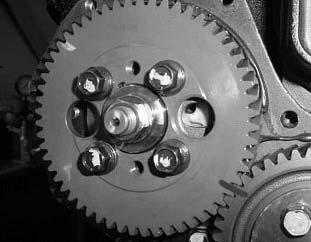

☞ Completely loosen locknut 4-11/2 of the drive pinion.
☞ Loosen bolts S
☞ Remove the fuel injection pump.
☞ Turn the gears until the marks coincide.
☞ Install the new fuel injection pump.
☞ Check the marked position of the drive pinion on the fuel injection pump (fig. 4-11).
☞ Loosen and tighten nut 4-11/2, tighten screws S
☞ Check injection time
– see Injection time on page 4-6.
☞ Replace the gear casing cover 4-10/1 on the fuel injection pump.
☞ Replace the injection lines.
☞ Twist the fuel shut-off valves on the fuel filter and the water separator to the ON position.
☞ Bleed the fuel system – see Bleeding the fuel system on page 3-10
IMPORTANT!
Do not loosen bolts 4-12/3 on the drive pinion of the fuel injection pump. These bolts determine the precise setting of the fuel injection pump and are set by the manufacturer.
4.8Adjustingenginerpm
IMPORTANT!
Maximum engine rpm is set at the factory and must not be modified. Adjust engine rpm without load.
☞ Run the engine until it reaches operating temperature.
☞ Check idling speed A and maximum rpm B with all attachment functions in neutral.
➥ Idling speed: 1300 +/- 50 rpm.
➥ Max. speeds: 2375 +/- 10 rpm.
4.9Compression
☞ Remove the injection lines and nozzles.
☞ Remove the plug for the cut-off solenoid to set the fuel injection pump to zero delivery.
☞ Crank the engine 2-3 revolutions (do not attempt to start the engine).
☞ Mount the compression gauge on the cylinder you want to measure.
☞ Crank the engine with the starter and read the pressure indicated by the pressure gauge.
➥ Specified value: 508 +/- 15 psi (35 +/- 1 bar) @ 250 rpm.
➥ Limit value: 406 +/- 15 psi (28 +/- 1 bar) @ 250 rpm.
4.10Checkingthecoolantthermostat
☞ Remove the thermostat.
➥ The thermostat is located on the water pump – see 3TNV76-NNS engine overview on page 4-1.
Thermometer
Thermostat
☞ Heat the thermostat in a container with water.
☞ Using a thermometer, check whether the thermostat opens at 157.1° – 162.5° F (69.5° – 72.5° C)
4.11Checkingthethermalswitch
Thermometer
☞ Remove the thermal switch.
☞ Heat the thermal switch in a container with antifreeze or oil.
☞ Using an ohmmeter, measure the resistance of the thermal switch.
➥ The switch must allow the coolant to pass at a temperature of 225° – 235° F (107° – 113° C).
Thermal Switch
Test probes
4.12Oilpressureswitch
Measurement probe
☞ Remove the cable connection from the oil pressure switch (in the area of the cut-off solenoid).
☞ Start the engine; check for correct idling speed (1300 +/- 50 rpm).
☞ Using an ohmmeter, measure the resistance of the oil pressure switch.
➥ Infinite resistance indicates the oil pressure switch is OK.
➥ The oil pressure switch is defective if the oil can pass out of the connection.
4.13Checkingthecoolantcircuit
Coolantsystemleakagecheck
☞ Completely fill the radiator.
☞ Mount a hand pump adapter onto the radiator as shown.
☞ Using a hand pump, increase the pressure in the cooling system to about 34 psi (2.3 bar).

➥ Check the coolant lines/connections for leaks if the pressure drops at the pressure gauge.
Radiatorcapcheck
☞ Remove the radiator cap and mount it onto a pressure tester as shown.
☞ Increase the pressure to about 34 psi (2.3 bar) (stamped onto the radiator cap) with the pressure tester.
➥ The radiator cap must open.
Radiator cap
4.14Enginetroubleshooting
ProblemPossiblecauses
Engine oil wrong SAE grade
Incorrect fuel grade
Defective or dead battery
Loose or oxidized cable connections in starter circuit
Starter defective, or pinion does not engage
Incorrect valve tip clearance
Fuel injector defective
Engine does not start or is not easy to start
Starting relay defective
Glow plug defective
Fuse defective
Fuel filter dirty
Air filter very dirty
Cutoff solenoid does not engage starter
High pressure in hydraulic system preventing engine start
Air in fuel system
ProblemPossiblecauses
Incorrect fuel grade
Incorrect valve tip clearance
Injection line leaks
Engine starts, but does not run smoothly or faultless
Defective fuel injector
Fuel filter dirty
Air in fuel system
Oil level too low
Oil level too high
Air filter dirty
Cooler fins dirty
Defective fan, torn or loose V-belt
Engine overheats; temperature warning system responds
Resistance in cooling system too high, flow capacity too low
Fuel injector defective
Low coolant level
Water pump defective
Cooling system leaks
Oil level too high
Incorrect fuel grade
Fuel filter dirty
Air filter dirty
Insufficient engine output
Incorrect valve tip clearance
Injection line leaks
Fuel injector defective
Air in fuel system
Injection line leaks
Engine does not run on all cylinders
Defective fuel injector/injection pump
Oil level too low
Insufficient or no engine oil pressure
Machine inclination too high
Engine oil wrong SAE grade
Oil level too high
Machine inclination too high
Engine oil consumption too high
Engine oil wrong SAE grade
Worn piston rings
Engine smoke
ProblemPossiblecauses
Oil level too high
Machine inclination too high
Blue
Engine oil combustion (defective cylinder-head gasket)
Engine oil wrong SAE grade
Worn piston rings
Engine starting temperature too low
Incorrect fuel grade
White
Fuel injector defective
Extreme misalignment of injection time
Coolant combustion (defective cylinder-head gasket)
Air filter dirty
Defective fuel injector (drips)
Black
Incorrect fuel injection pump setting
Incorrect valve tip clearance
Dirty injection nozzle
5Hydraulicsystem
The hydraulic system is governed by the throttle.
Twin variable-displacement pump and two gear pumps.
Pos.Description
1Port P4
2Pressure limiting valve
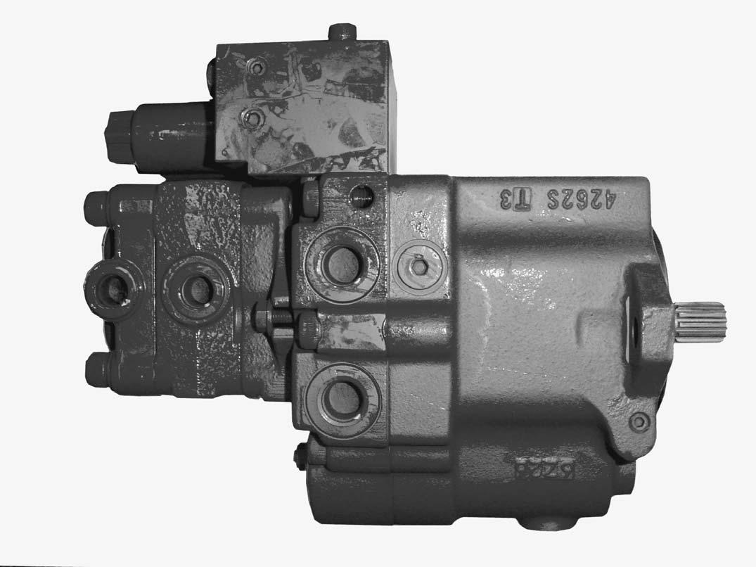
3Bleed screw
5Port P1
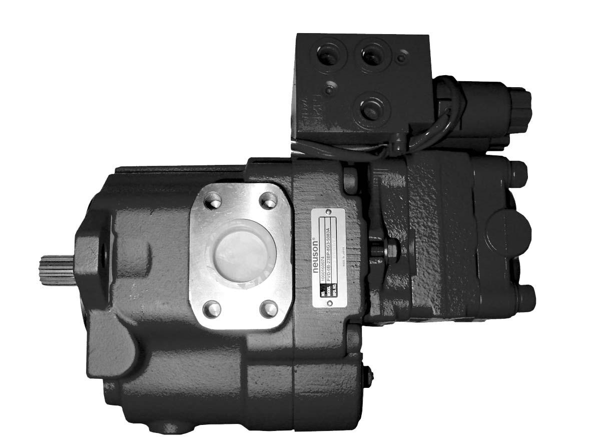
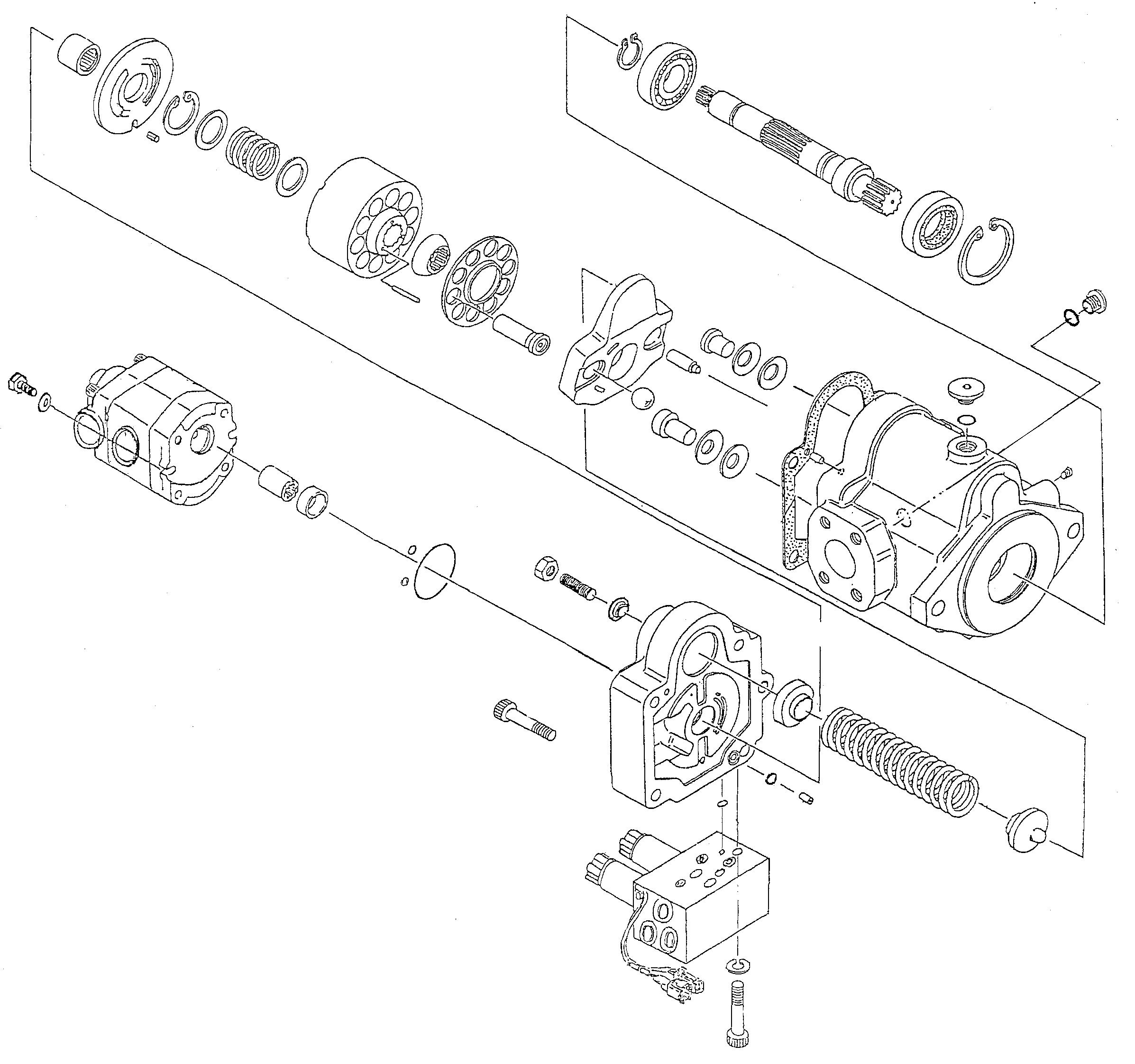

5.2Mainvalveblock
3rdcontrolcircuit(option)


