1 minute read
Hydraulic system

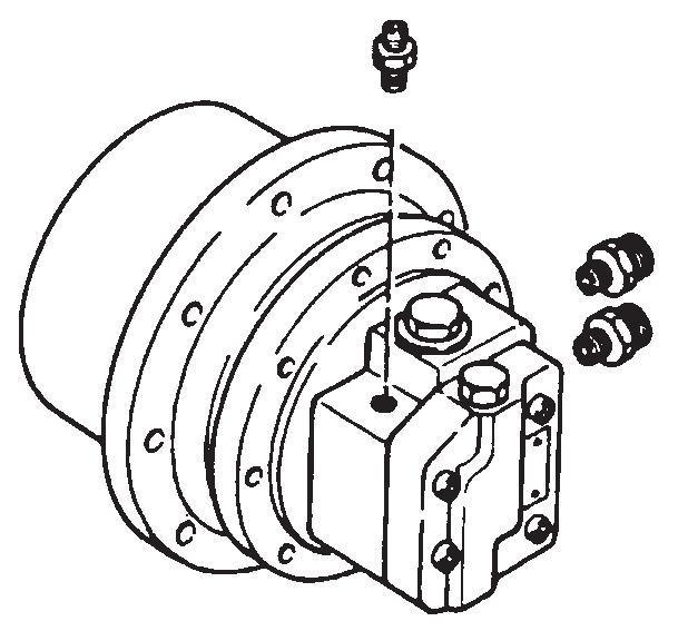
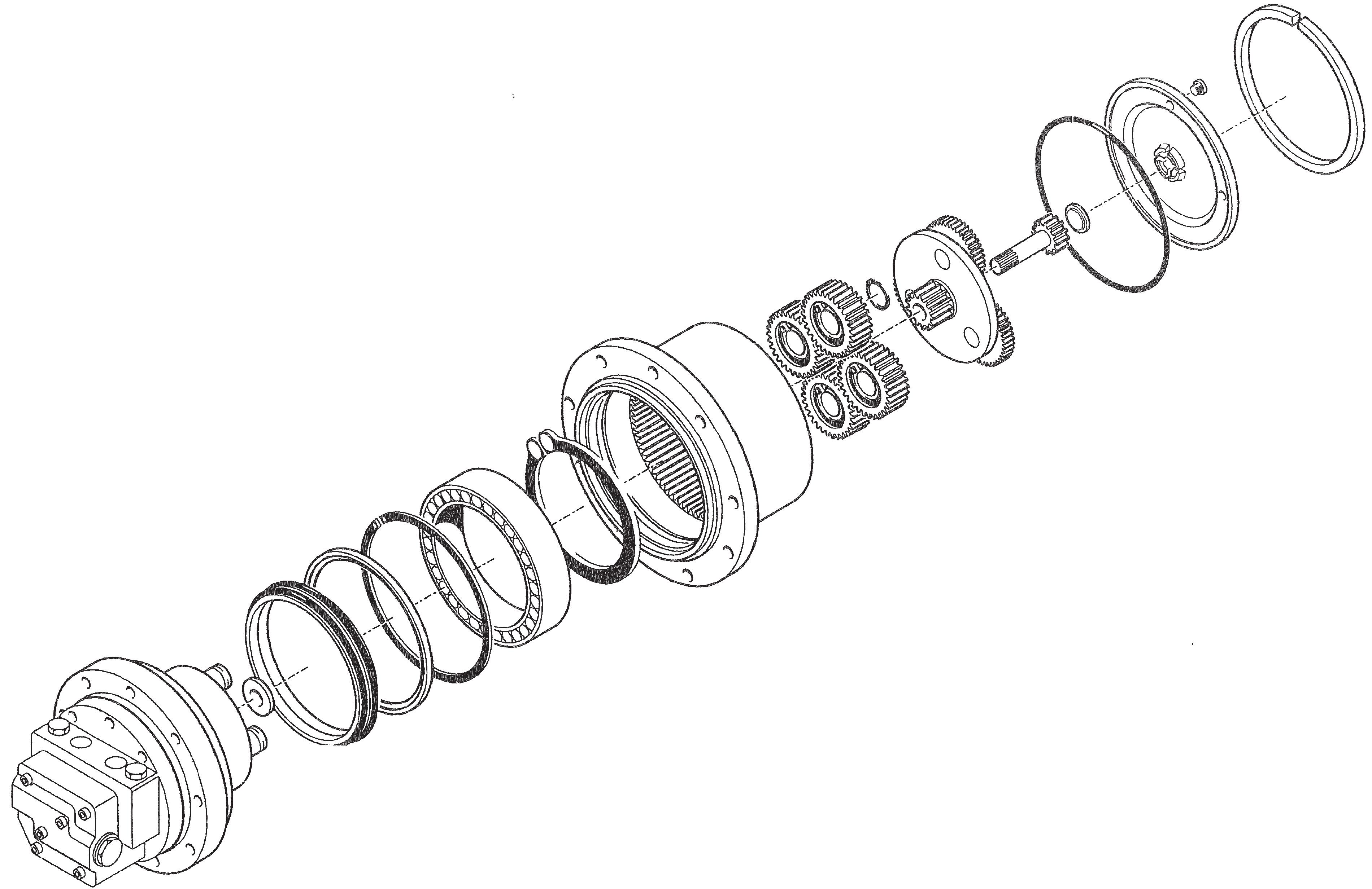
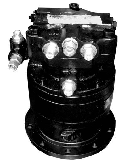
5.10Traveldrive
• Swash-plate piston motor
• The drive has two speed ranges switched via two capacity positions
Pos.Description
1Drive port (-> swivel joint right 4/left 3)
2Drive port (-> swivel joint right 2/left 5)
32nd speed range port (-> swivel joint 8)
4Directional valve forward/reverse = brake piston
5Return oil port (-> swivel joint 1)
6Solenoid valve 2nd speed range
7Pressure limiting valves
8Shuttle valve
Function
Driving:
If high pressure is applied to one of the drives, the brake release piston is actuated first and passes high pressure on to the brake cylinder, which releases the brake. The throttle slowly actuates the brake piston at the same time. Brake piston control causes high pressure to be applied to the motor, which starts turning.
Stopping:
The oil flows from both ports to the tank upon releasing the joystick. The brake release piston and the brake piston (slowly actuated by the throttle) return to their base positions. The slow drop of the brake piston prevents the hydraulic motor from coming to an abrupt standstill. With the brake piston in neutral position, the ports are no longer connected to the motor, which can no longer turn. The brake release pressure is reduced via both throttles shortly afterward.
2speedrangefunctions
Speedrange1
• “High speed” switch 38 (see page 1-9): switched off The solenoid valve on the pilot oil supply unit is de-energized, and the oil flows through the control line to the tank. The swash plate of the hydraulic motor is fully swivelled in this position, i.e., the motor is at maximum capacity.
➥ The engine runs at slow speed but at maximum tractive power.
Speedrange2
• “High speed” switch 38 (see page 1-9): switched on The solenoid valve is energized, and the swash plate of the hydraulic motor returns to base position, i.e., the motor is at minimum capacity.
➥ The engine runs at high speed but at low tractive power.
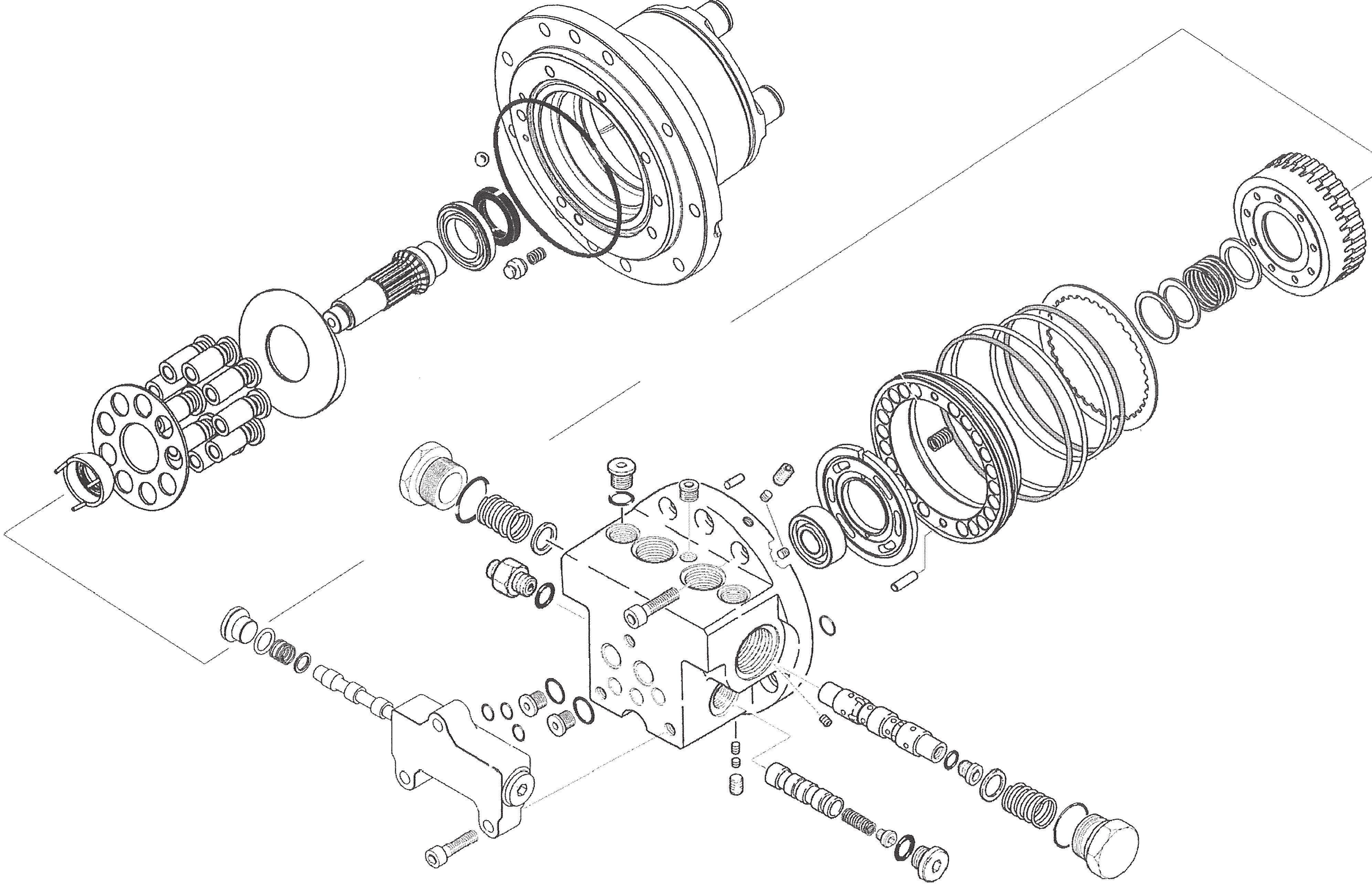
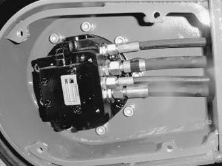
5.11Swivelunit
Hydraulically controlled swash-plate piston motor with maintenance-free swivel gearbox and mechanical motor brake.
Pos.Description
1SH brake release port (-> shuttle valve)
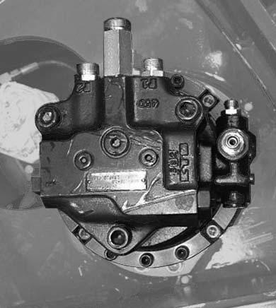
2Pilot control pressure port (-> pilot oil supply unit)
3Brake release valve
4Right side rotation port (-> main valve block)
5Anti-cavitation line port (-> main valve block/tank)
6Left side rotation port (-> main valve block)
7Shock anti-cavitation valves
8Return oil port (-> tank)
9Brake piston
The shock anti-cavitation valves are dampened for smooth braking.