12 minute read
19. INSTALLING BUCKET OR ATTACHMENT TO SKID STEER TOOL CARRIER


IMPORTANT: Refer to Pages 62 to 63 for instructions concerning Skid Steer Tool Carrier Handles Disengaged and Engaged Positions.
CAUTION: Before leaving the tractor seat, stop the engine and lock brakes when installing or removing bucket or attachment.
CAUTION: Do not stand, walk, or work under a raised loader or attachment unless it is securely blocked or held in position. Accidental movement of valve handle/handles or leaks in the hydraulic system could cause the loader to drop, or attachment to dump, causing severe injury.
19.1. OPERATING INSTRUCTIONS
19.1.1. To attach bucket or attachment to loader, lower loader boom to ground with Skid Steer Tool Carrier attachment rolled forward slightly.
19.1.2. To position handles into the handle disengaged position, pull skid steer tool carrier handle upward.
Pull Handles Upward
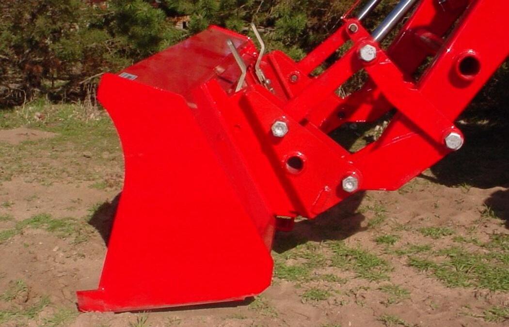
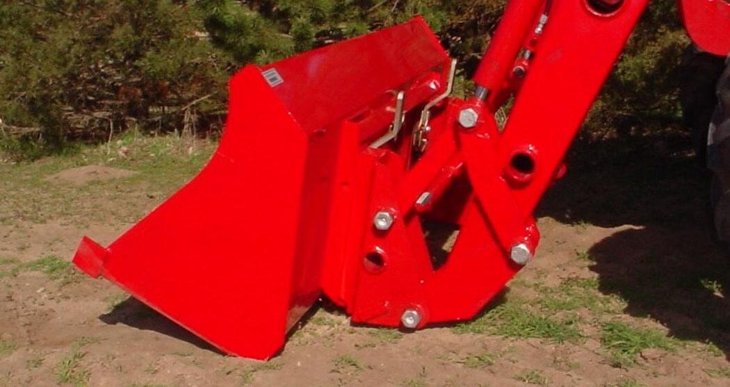
19.1.3. Roll Skid Steer Tool Carrier attachment forward by extending tilt cylinders just enough to allow Skid Steer Tool Carrier upper vee to engage Skid Steer attachment vee channel. Drive tractor forward, aligning Skid Steer Tool Carrier vee components.
Align Skid Steer Tool Carrier vee with Skid Steer Attachment vee channel.
NOTE: Over extension of tilt cylinders during this operation could cause damage to Skid Steer Tool Carrier handles due to handles contacting bucket or attachment.
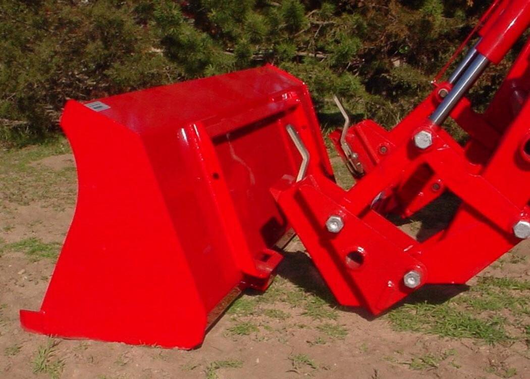
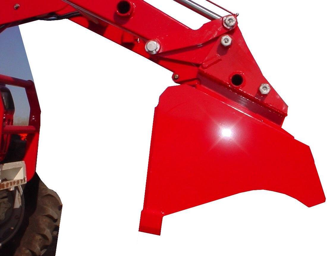
19.1.4. When Skid Steer Tool Carrier attachment is aligned with bucket or attachment, raise loader boom slowly making sure Skid Steer Tool Carrier vee components engage. Then roll Skid Steer bucket or attachment back slowly.
19.1.5. Position loader so attachment is approximately 1" off ground.
19.1.6. To position handles into the handle engaged position, push skid steer tool carrier handle downward until they latch into position.
Push Handles Downward.
NOTE: Handles should be positioned parallel to ground if properly latched.
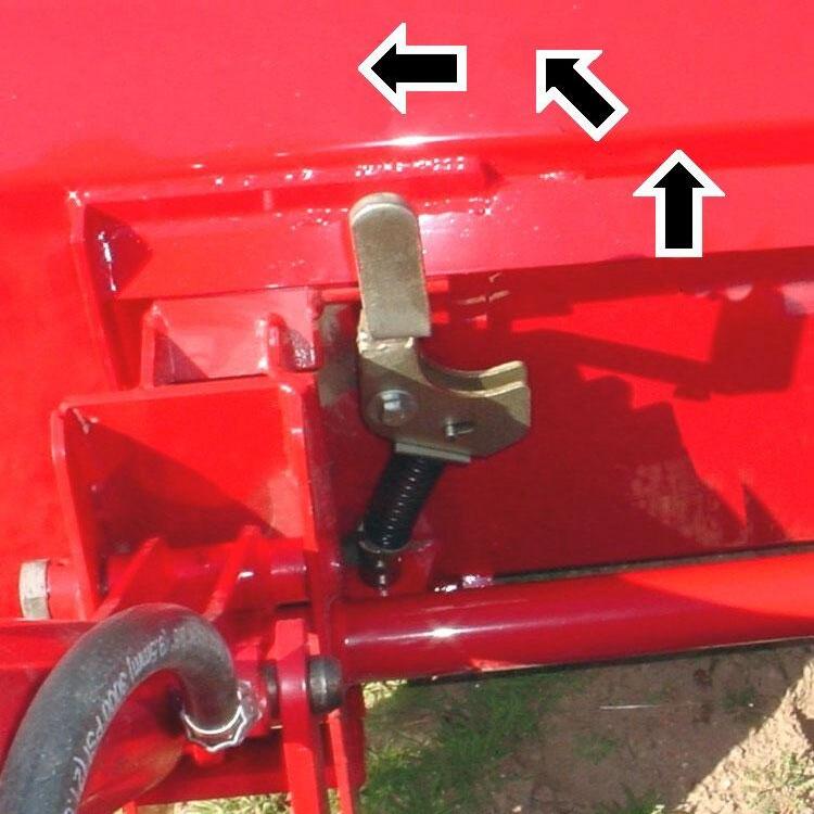
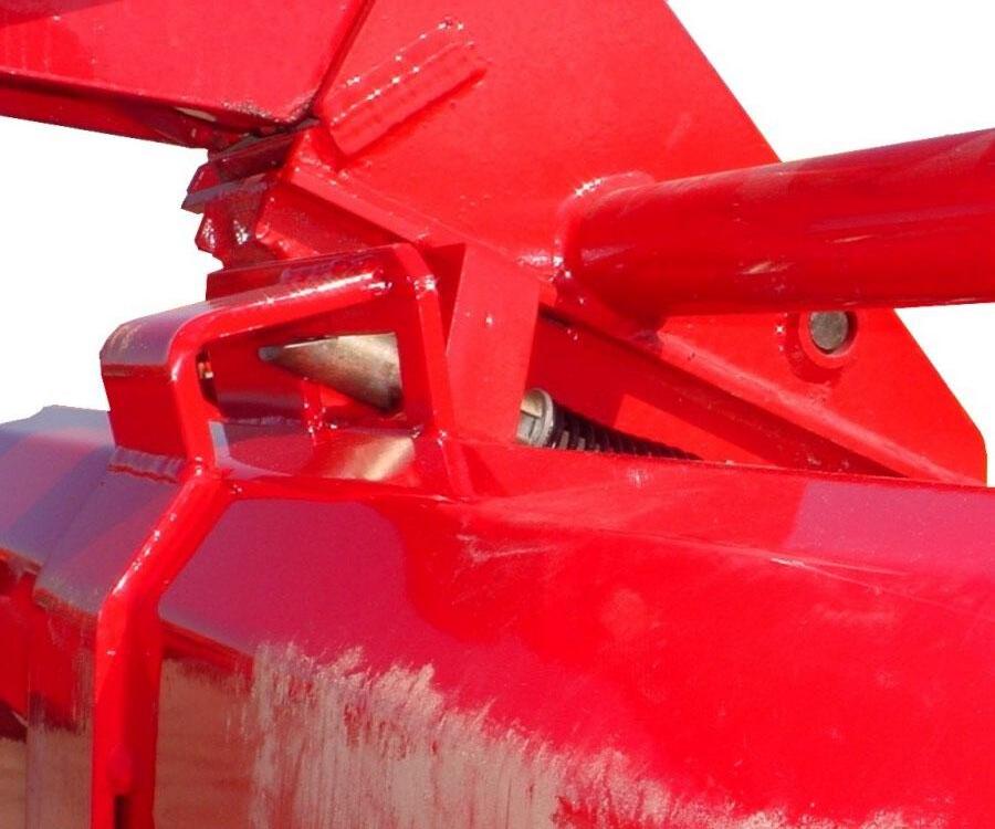
IMPORTANT: If properly latched into skid steer tool carrier attachment, the lower skid steer groove pin should be contacting quick attach pin support bar.

19.1.7. Position loader so attachment is approximately 1" off ground.
(2) Handles engaged position.
(3) Groove pin.
(4) Contact point.
(5) Pin support bar.
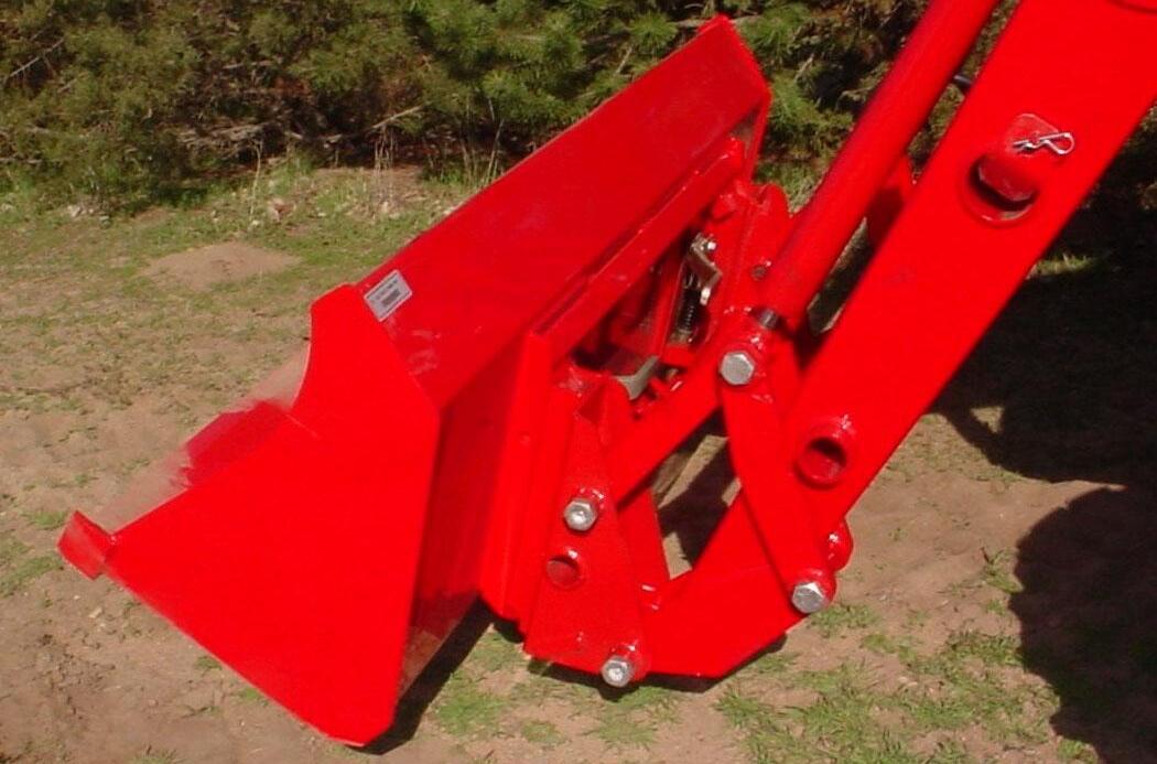
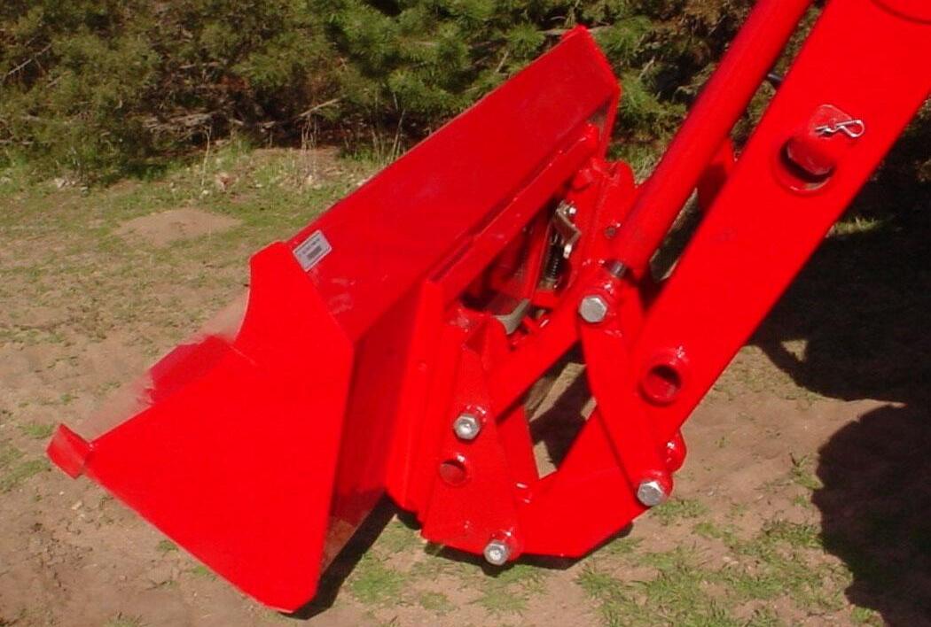
19.1.8. Check that bucket or attachment is securely attached to Skid Steer Tool Carrier by raising loader boom 3 to 4 feet, dumping bucket or attachment against stops, and checking to be sure bottom of bucket or attachment does not roll forward away from Skid Steer Tool Carrier Assembly.
19.1.9. Inspect Skid Steer Tool Carrier attaching areas to verify that Skid Steer Tool Carrier pins have engaged bucket or attachment fully.
19.1.10. Inspect Skid Steer Tool Carrier attaching areas to verify that Skid Steer Tool Carrier pins have engaged bucket or attachment fully.
19.1.11. Skid Steer Quick Attach (1) lower roll pin should be contacting (2) Quick attach pin support bar.
19.1.12. Skid Steer Quick Attach (3) pin should be engaged into (4) bucket or attachment as shown.
WARNING: A bucket or attachment that is not securely locked into Skid Steer Tool Carrier could come off during loader operation causing serious injury or death.
19.1.13. If installing an attachment utilizing a third cylinder hydraulic circuit, connect loader hose quick couplers at attachment quick couplers.
20. REMOVING BUCKET OR ATTACHMENT FROM SKID STEER TOOL CARRIER
IMPORTANT: Refer to Pages 62 to 63 for instructions concerning Skid Steer Tool Carrier Handles Disengaged and Engaged Positions.
CAUTION: Before leaving the tractor seat, stop the engine and lock brakes when installing or removing bucket or attachment.
CAUTION: Do not stand, walk, or work under a raised loader or attachment unless it is securely blocked or held in position. Accidental movement of valve handle/handles or leaks in the hydraulic system could cause the loader to drop, or attachment to dump, causing severe injury.
20.1. OPERATING INSTRUCTIONS
20.1.1. To disconnect bucket or attachment from loader, position bucket or attachment slightly rolled back and approximately 1" off of ground.
20.1.2. To position handles into the handle disengaged position, pull skid steer tool carrier handle upward.
Pull Handles Upward
20.1.3. Roll bucket or attachment forward and lower to ground. Back loader away from bucket or attachment.
NOTE: Over extension of tilt cylinders during this operation could cause damage to Skid Steer Tool Carrier handle due to handle contacting bucket or attachment.
20.1.4. If removing an attachment utilizing a third cylinder hydraulic circuit, disconnect loader hose quick couplers from attachment quick couplers. Secure and store loader hoses on loader frame.
21. SKID STEER BUCKET
IMPORTANT: Read safety information in this section and on decals before operating attachments.
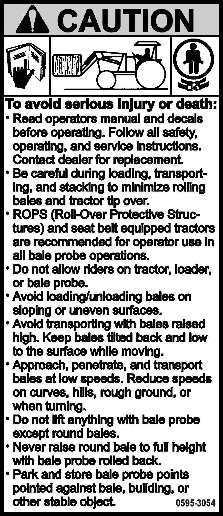
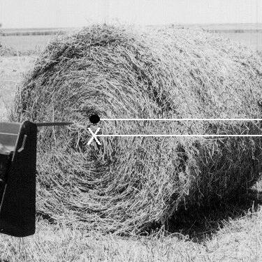
WARNING: To avoid serious injury or death from large round or square hay bale handling:
• Use only Factory bale spear or bale retaining device handler attachment when handling round bales.
• Do not handle large square bales without a retaining device handler attachment
• Do not use buckets, forks, or other attachments without bale retaining devices.
• Do not use loader for handling large, heavy objects such as logs, tanks, etc.
WARNING: To avoid serious injury or death, realize handling large heavy objects can be extremely dangerous due to:
• Danger of rolling the tractor over.
• Danger of upending the tractor.
• Danger of the object rolling or sliding down the loader arms onto the operator.
WARNING: To avoid serious injury or death:
• Do not lift or carry anyone on buckets, forks, probes, or any other portion of the loader or loader attachments.
• Avoid contact with electrical power lines by loader or attachment
WARNING: Inadvertent movement of the loader or attachment could result in serious injury or death.
21.1. SKID STEER BUCKET
21.2. INSTALLATION INSTRUCTIONS TO SKID STEER TOOL CARRIER
IMPORTANT: Refer to Pages 64 to 66 for instructions concerning Installing Attachment to Skid Steer Tool Carrier.
IMPORTANT: Refer to Page 67 for instructions concerning Removing Attachment from Skid Steer Tool Carrier.
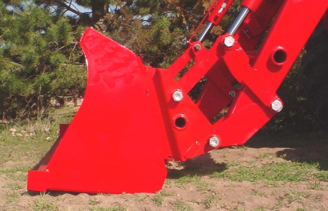
22. SKID STEER BALE SPEAR
IMPORTANT: Read safety information in this section and on decals before operating attachments.
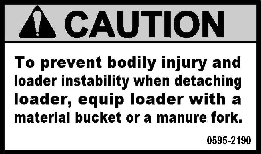
IMPORTANT: It is not recommended that loader be detached with bale spear attached. Loaders will park safely; however, bale spear could be damaged during parking. Always detach loader with bucket or other loader Factory approved attachment attached.
CAUTION: When transporting a round bale, tilt the bale spear slightly back from level and carry the load in a low position.
CAUTION: Never raise round bale to full height with bale spear rolled back as serious injury or death could occur.

CAUTION: To prevent bodily injury, park and store bale spear with points pointed against bale, building, or other stable object.
22.1. SKID STEER BALE PROBE
IMPORTANT: This spear is a high strength alloy – drop forged steel and should not be welded or heattreated.
IMPORTANT: Maximum load limit on super penetrator bale spear is 2,000 pounds.
22.2. ASSEMBLY INSTRUCTIONS
22.2.1. Install Bale Spear into tapered sleeve and secure with nut. Torque nut 515 ft. lb. Failure to follow these instructions could cause damage to spear and void your warranty.
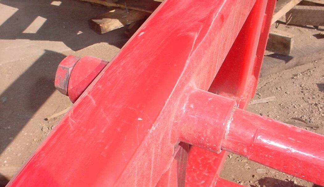
(1) Upper Spear.
Flat surface of spear located upward.
(2) Tapered Sleeve.
(3) Upper Spear Nut, 28mm. Torque nut to 515 ft. lb.
22.3. INSTALLATION INSTRUCTIONS TO SKID STEER TOOL CARRIER
IMPORTANT: Refer to Pages 64 to 66 for instructions concerning Installing Attachment to Skid Steer Tool Carrier.
IMPORTANT: Refer to Page 67 for instructions concerning Removing Attachment from Skid Steer Tool Carrier.
22.4. OPERATING INSTRUCTIONS
22.4.1. With bale spear level with ground, slowly spear bale slightly above center.
22.4.2. With all three spears completely engaged into bale, tilt bale spear slightly back from level and transport the load in a low position. Spear bale slightly above center of bale.
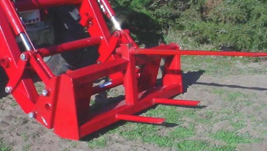
23. SKID STEER PALLET FORK
IMPORTANT: Read safety information in this section and on decals before operating attachments.
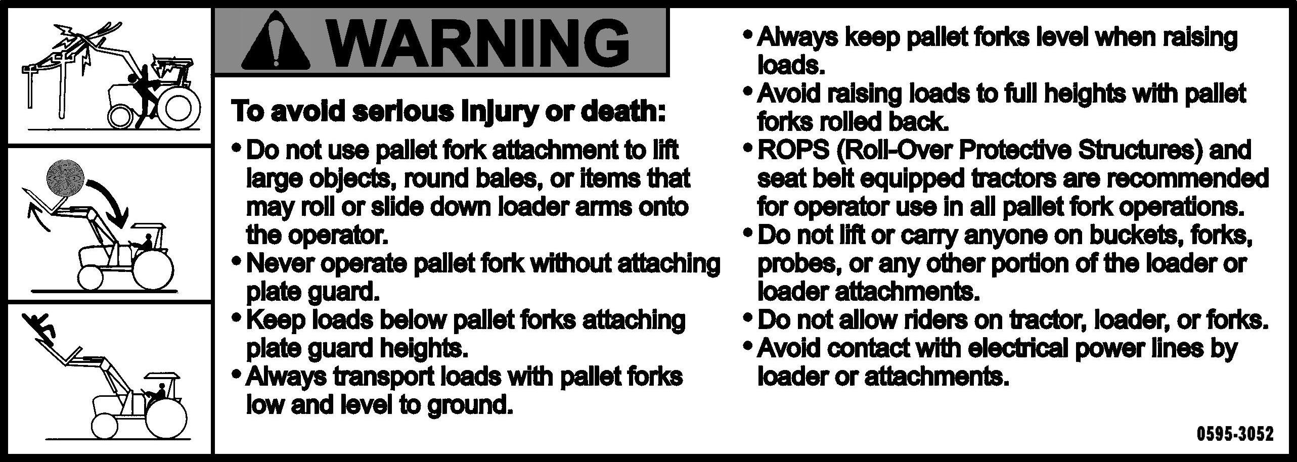
WARNING: The pallet fork attachment is specifically designed to engage and load palleted materials. Do not use forks to handle large loads such as bales, posts, etc. as they can fall or roll back onto operator causing serious injury or death.
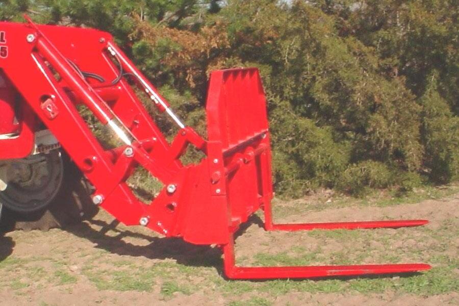
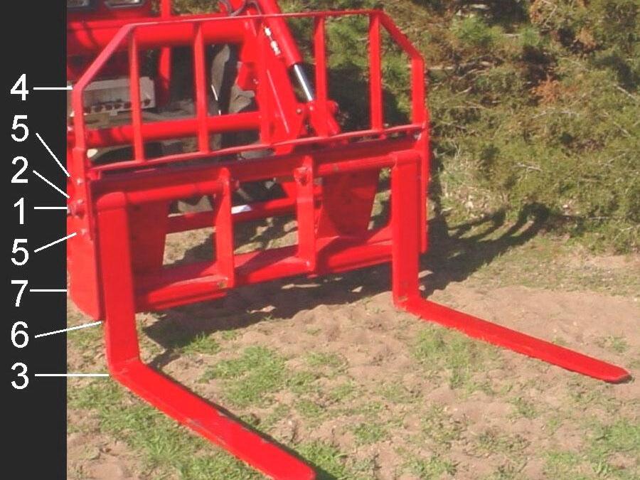
23.1. SKID STEER PALLET FORK
23.1.1. The Skid Steer Pallet Fork has two tines each 1-1/2" x 4" x 42".
23.2. ASSEMBLY INSTRUCTIONS
23.2.1. Install (4) guard to (7) pallet fork frame using (5) 1-2" x 1-1/2" bolt, lockwasher, flatwasher, and nut, 2 places each side.
23.2.2. Install (3) forks to (7) pallet fork frame using (1) pins, 2 places secure using (2) 3/8" x 2-1/2" bolts, lockwashers, and nuts, 4 places.
23.2.3. Locate (6) hooks on (3) forks on backside of angle to prevent fork rotation.
23.3. INSTALLATION INSTRUCTIONS TO SKID STEER TOOL CARRIER
IMPORTANT: Refer to Pages 64 to 66 for instructions concerning Installing Attachment to Skid Steer Tool Carrier.
IMPORTANT: Refer to Page 67 for instructions concerning Removing Attachment from Skid Steer Tool Carrier.
23.4. OPERATING INSTRUCTIONS
The operator must keep the load centered and as far back on the forks as possible. Operator must always keep load level. Carry the load low and at a slow speed.
23.5. PARKING INSTRUCTIONS
If parking loader from tractor with pallet fork attachment, move forks outward to widest position (see photo above). NOTE: Move Forks outward to Widest Position
24. TROUBLE SHOOTING PROCEDURES
This Trouble Shooting Chart is provided for reference to possible loader operational problems.
Determine the problem that best describes the operational problem being experienced and eliminate the possible causes as listed by following the correction procedures.
For further assistance contact your dealer.
24.1. TROUBLE SHOOTING FOR ALL LOADERS PROBLEM POSSIBLE CAUSE CORRECTION
Lift and Tilt Cylinders inoperative
Low hydraulic fluid level. Check and replenish hydraulic fluid. Hydraulic hoses connected improperly. Check and correct hydraulic hose connections
Hydraulic Hoses to/from loader valve blocked.
Loader valve or tractor main relief valve stuck open.
Check for damaged (kinked) hoses, etc.
Check system pressure. Repair or replace relief valve.
Low system pressure supplied from hydraulic pump. Check system pressure. Repair or replace pump.
Loader valve linkage broken. Inspect. Repair as required. Quick disconnect coupler(s) are not fully connected. Check coupler connections. Replace coupler(s) if necessary.
Hydraulic hose or tubeline blockage. Check all hoses and tubes for leaks, damage, or restrictions. Replace damaged or restricted hoses or tube lines.
Cylinder piston assembly defective (not sealing).
Check cylinders for internal leakage as described in service section under cylinder leakage tests.
Loader valve blockage. Inspect for blockage. Disassemble valve if necessary.
Lift and/or tilt cylinders operate in wrong direction relative to valve handle position
Attachment will dump but will not rollback
Slow or erratic lift
Hydraulic hoses connected incorrectly. Correct hydraulic hose connections.
Hydraulic circuit connected incorrectly. Refer to plumbing diagram on Page 32 and correct hose connections.
Low hydraulic fluid level. Check and replenish hydraulic fluid. Cold hydraulic fluid. Allow hydraulic system to warm up to operating temperature.
Engine R.P.M. too slow (hydraulic pump R.P.M. too slow).
Excessive weight in bucket. Material weight exceeds maximum specified loader capacity.
Loader valve linkage binding/defective.
Increase engine speed to obtain satisfactory loader operation.
Reduce material load.
Check loader valve linkage and repair if worn/defective.
Problem
Possible Cause Correction
Aeration of hydraulic fluid Refer to "Aeration of Hydraulic Fluid".
Quick disconnect coupler restriction or coupler. Check coupler connections. Repair or replace.
Hydraulic hose or tubeline restriction (hoses/tubeline kinked or pinched).
Check hoses and tubelines for evidence of restriction.
Lift cylinder piston assembly leakage. Check cylinders for leakage. Repair as needed.
Relief valve erratic or set below specifications. Check and reset relief valve setting as needed.
Loader valve leaking internally. (Bypassing fluid within valve.)
Replace loader valve and recheck operation.
Inadequate hydraulic pump capacity. Refer to "Hydraulic Pump Capacity Inadequate".
Inadequate lifting capacity Engine R.P.M. too slow. Increase engine R.P.M.
Excessive load – material weight exceeds specified loader capacity. Reduce Load.
Relief valve setting below specifications. Check and reset relief valve setting as needed.
Lift cylinder piston assembly leakage. Check cylinders for leakage. Repair as needed.
Loader valve leaking internally. Replace loader valve and recheck operation.
Hydraulic pump defective. Refer to "Hydraulic Pump Capacity Inadequate".
Aeration of Hydraulic Fluid (generally indicated by foamy appearance of fluid).
Low hydraulic fluid level. Check and refill hydraulic system to proper level.
Air leaking into suction side of hydraulic pump. Check for loose or defective connections between reservoir and hydraulic pump.
Hydraulic fluid foaming due to improper hydraulic oil usage. Refer to Tractor Operator’s Manual and replace hydraulic oil using recommended hydraulic oil.
System relief valve squeals. Cold Hydraulic Fluid. Allow hydraulic fluid to warm up to operating temperature.
Excessive load in bucket. Weight exceeds specified loader capacity. Reduce load.
Relief valve setting below specifications. Check and reset valve setting as needed.
Hydraulic hose, tubeline, or quick disconnect coupler restriction. Check for evidence of restriction in hydraulic oil flow. Repair or replace defective components.
Problem
Loader drops with loader valve spool in "Centered" position (no external oil leakage evident.)
Possible Cause Correction
Cylinder Piston assembly leakage. Check cylinders for leakage.
Loader valve internal leakage. Replace loader valve and recheck. Note: A gradual drop over an extended period of time is a normal condition.
Loader valve spool(s) will not return to centered position. Valve handle linkage binding. Determine origin of binding and repair.
Loader valve spool centering is broken. Replace centering spring.
Loader valve spool binding in valve body spool bore. Disassemble valve for inspection and repair.
Loader bucket moves freely after dumping load Tilt cylinder cavitation has occurred. Use of regen function while dumping load will eliminate problem. Refer to Page 32. Contact Factory for optional orifice kit availability.
External hydraulic fluid leakage. Loose hydraulic connection. Tighten loose connections. Defective hydraulic hose, tubeline, adapter fitting or adapter fitting oring.
Check for origin of oil leak and replace defective part.
Loader valve o-rings defective. Replace defective o-rings.
Loader valve spool or body damaged or worn. Replace loader valve.
Cylinder rod packing set leakage. Check cylinders for leakage. Repair as needed.
Hydraulic pump capacity inadequate. Cold hydraulic fluid. Allow hydraulic fluid to warm up to operating temperature.
Engine R.P.M. too slow. Increase engine R.P.M.
Low hydraulic fluid supply. Refer to Tractor Operator’s Manual for service recommendations.
Hydraulic hose restriction. Check for evidence of restriction in hydraulic hoses.
Hydraulic pump defective. Refer to Tractor Operator’s manual for recommended service procedures. Replace hydraulic pump if determined to be defective.
Lift cylinder rods bend when lift cylinders extended.
Bucket cutting edge wear is uneven side to side
Excessive shock load on lift cylinders during transport. Replace defective parts. Review and observe proper and safe operational practices.
Bucket is not level to ground. Check rear tire inflation and adjust to level bucket to ground.
Problem
Bucket cutting edge wear rate is excessive. (Wear rate is even across full width of bucket).
Possible Cause Correction
Incorrect operational practices. Excessive down pressure placed on bucket when used on hard abrasive surfaces.
Refer to operation – scraping section for correct operating procedures. Utilize float position.
Bucket wear pads worn. Replace wear pads. Note: Extensive use of bucket on concrete or asphalt surfaces will accelerate wear rate of bucket cutting edge.
Loader is slow and/or will not dump.
Hydraulic oil too heavy. Change to proper oil.
Oil filter plugged. Clean or replace filter. Hydraulic pump worn. Repair or replace pump.
Oil line restricted or leaking. Check all hoses and tubes for leaks, damage, or restrictions. Replace damaged or restricted hoses or tube lines.
Loader valve does not shift properly. Inspect clean, repair, or replace valve.
Cylinder leaks internally. Replace seals. Faulty valve. Repair or replace valve.
Loader chatters or vibrates when raising or lowering.
Air in hydraulic system. Cycle lift cylinders and tilt cylinders.
Oil level too low. Add oil as required.
Slow leakdown. Worn loader valve. Have authorized Mahindra dealer replace seals.
Worn cylinder piston seals. Have authorized Mahindra dealer replace seals.
Attachment will dump but will not rollback
Hydraulic circuit connected incorrectly. Check that Port "C" of loader valve is connected to tilt cylinder base end and that Port "D" of loader valve is connected to rod end of tilt cylinder.
24.2. TROUBLE SHOOTING FOR LOADERS WITH OPTIONAL SELF LEVELING PROBLEM POSSIBLE CAUSE CORRECTION
Bucket does not self-level
Bad float switch in the valve handle. Repair or replace the handle and switch.
On-Off Solenoid Valve stuck in the ON position. Check the Solenoid Valve on Self Level Valve.
Bucket does not maintain level while raising or lowering at engine speeds other than high idle. Loader valve lift spool not fully stroked. Fully stroke the loader lift spool.
Bucket does not maintain level while raising at high idle.
Bucket self-leveling is designed to work optimally at high RPM. Run engine at high RPM (1700 or above).
Bucket does not maintain level while lowering at high idle.
Flow divider spool stuck. *Check flow divider spool for free operation. (Check for contamination.)
Raise counterbalance valve stuck. *Remove and check for contamination.
Flow divider spool stuck. *Check flow divider cartridge for free operation.
Lower modulator valve stuck. *Remove and check for contamination. (Spool should move freely in bore.)
Lift check valve stuck (cartridge). *Remove and check for contamination.
Excessive bucket drift in the dump direction.
Bad bucket cylinder seal. Repack cylinder. Raise counterbalance valve stuck. *Remove and check for contamination.
Bad Anti-Cavitation relief valve cartridge. *Check Anti-Cavitation check valve cartridge. Remove and check for contamination or replace.
Excessive loader control valve bucket spool port leakage. Check with Factory on acceptable valve spool leakage rate. Replace if required.
Bucket moves freely when putting down pressure on cutting edge.
Loader bounces with lowering load.
Self-Leveling does not operate after initial hook-up.
Pilot operator check is not closing (cartridge plus pilot piston).
*Remove and check for contamination. Replace if required.
Low hydraulic flow. Increase tractor RPM to increase hydraulic flow.
Circuit not hooked up correctly. Check that circuits are hooked up as follows.
*NOTE: This service must only be accomplished by an Authorized Mahindra Service Person. Failure to follow these instructions will void warranty.