5 minute read
1. SPECIFICATIONS


taken with Mounting Kit, Hose Kit, and 78" Pin On Standard Bucket.
based on ASAE standards S301.3 and furnished for general information only as they can vary with different tractor models. Specifications are subject to change without notice and without liability therefore.
1.1. ATTACHMENT SPECIFICATIONS
2. INTRODUCTION
This manual provides safety, installation, operation, maintenance, removing, storing, and reinstalling instructions for your new midmount loader.
Your loader has been designed to give many years of satisfactory service. Successful operation and long life of the loader depends, of course, on proper operation and care. Please read this manual carefully and follow the instructions. Correct operation and maintenance will save much time and expense.
OBSERVE and follow all CAUTION, WARNING, and DANGER instructions to help prevent personal injury and damage to the loader. The reference to right hand (RH) and left hand (LH) used in this manual refers to the position when standing at the rear of the unit and facing forward.
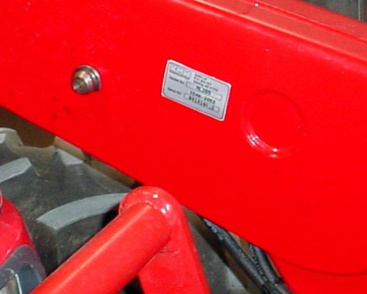
If, at any time, you have a service problem with your loader or need new parts, contact your local Mahindra dealer. Your dealer will need the loader model number and serial number to give you prompt, efficient service. The serial number plate is located on the LH inside front area of boom.
Before operating loader, check that your Dealer has covered the following information with you:
Equipment has been completely assembled as directed. Equipment has been functionally tested for proper operation.
Purchaser has been instructed in proper & safe operating methods:
Operators Safety Precautions
Tractor Wheel Tread-Tire & Inflation Recommendations
Tractor Hydraulic System & Loader Controls
Rear Ballast Recommendations
Hydraulic System Oil Level
Proper Loader Operation
Loader Removal
Loader Installation
Lubrication - Service Care
Storage
Warranty Coverage & Operators Manual explained to purchaser.
Mahindra ML170 Loader Serial Number Information
LOADER SERIAL NUMBER
DATE PURCHASED
DEALER NAME AND TELEPHONE NUMBER
3. INSTALLATION INSTRUCTIONS
CAUTION: Equip your tractor with a ROPS cab or frame for your protection. See your tractor/ROPS Operator Manual for correct seat belt usage.
Read entire instructions before beginning to install the loader. Personal injury and machine damage may be prevented if you read and understand these instructions and special safety messages. When you are in the tractor seat looking forward, the RH and LH sides of the tractor and loader are the same as your right hand and left hand.
3.1. TRACTOR PREPARATION
3.1.1. Tractor Front Tires
Use front tires of equal size and maintain equal pressure in each tire. The pressure of the front tractor tires must be increased to the maximum approved pressure recommended by the tire manufacturer to compensate for additional load placed on the tires with the Front End Loader. See your tractor Operator Manual. Adjust the front tires to the widest recommended setting on adjustable models for maximum stability. Front end weights must NOT be used while loader is on the tractor.
3.1.2. Tractor Rear Tires
Maintain equal pressure in each of the rear tires. Use the widest recommended rear wheel setting for maximum stability.
3.1.3. Tractor Ballast
CAUTION: To help prevent rollover, use recommended rear tractor ballast and widest wheel settings to maximize stability. See your tractor Operator Manual for recommendations
Front tractor weights must only be used when the loader is parked. Weights must be removed before remounting loader or serious damage will occur to loader or tractor front axle due to excessive weight. The use of adequate rear counterweight to counterbalance for maximum loader capacity is required for safe loader operation. Weight added to the rear of the tractor provides better traction and easier, more efficient loader operation.
IMPORTANT: Do not exceed the maximum load capacity of the tires on your tractor. See Tire and Wheel Specifications in tractor Operator Manual for more information.
3.1.4. Remove all loader components from shipping packaging.
WARNING: To avoid serious injury or death: Read before cutting bands or removing attaching straps. The loader may shift during shipping and handling, making it unstable on the pallet. Support loader with an overhead hoist or other suitable means prior to removing bands or attaching straps securing loader to pallet. Failure to do so could result in accidental tip-over of the loader that could cause serious injury to you and/or bystanders.
CAUTION: Lift and support all loader components safely.
3.2. MOUNTING KIT INSTALLATION
3.2.1. Position the tractor and loader on a hard level surface under a hoist.
3.2.2. Remove front weights from tractor.
IMPORTANT: Do not tighten any hardware until all components are attached onto the tractor.
CAUTION: Lift and support all loader components safely.
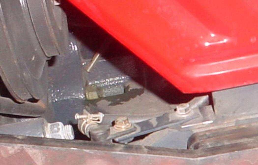
3.2.3. Check right hand side of tractor in front axle area. Reposition components as shown so they will clear loader bracket.
Reposition components
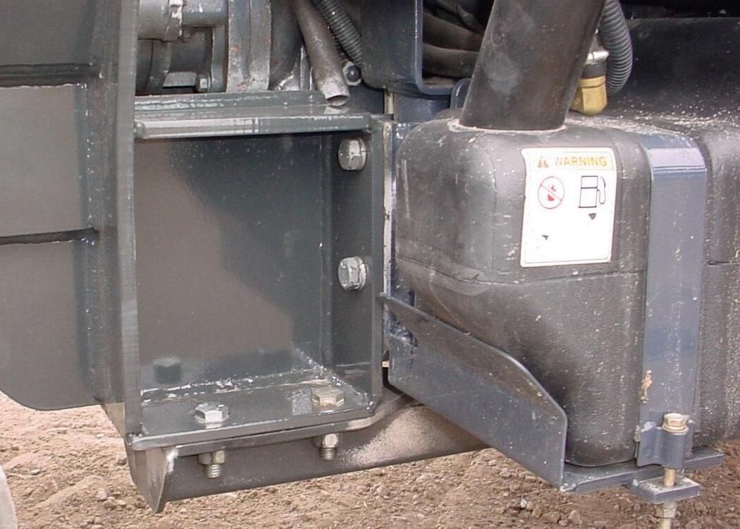
3.2.4. Position hoist with chain through center bracket hole to support bracket during installation. Position hoist with chain through this hole when mounting center bracket.
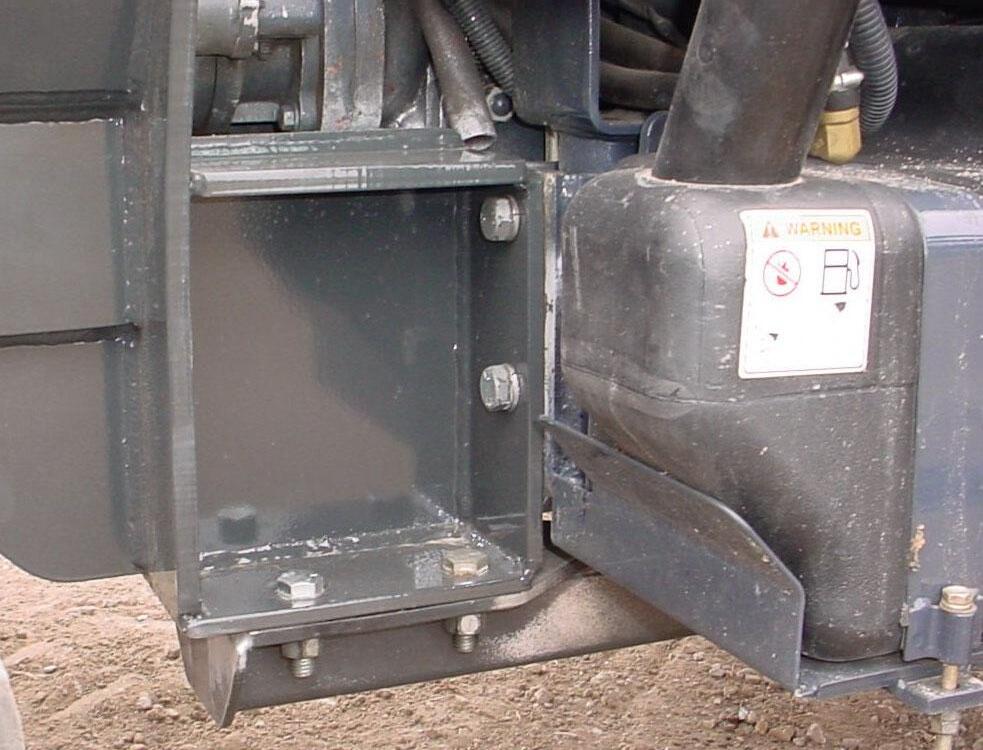
3.2.5. With hoist supporting center bracket, locate oscillation stop with tab under and toward front of tractor and 1/2" thick 4-hole spacer between center bracket and tractor. Install 16mm x 2.0P x 90mm hex bolts Grade 10.9, 5/8" lockwashers, and 5/8" flatwashers, 4 places. Do not remove hoist.
Oscillation Stop
Spacer, 4-Hole 16mm x 2.0P x 90mm Grade 10.9 Hex Bolt, 5/8" Lockwasher, and 5/8" Flatwasher, 4 places.
Center Bracket
3.2.6. With hoist supporting Center Bracket center bracket, install 16mm x 2.0P x 30mm Grade 8.8 hex bolts and 5/8" lockwashers, 2 places inside and 2 places outside of bracket in front area of cab. Do not remove hoist.
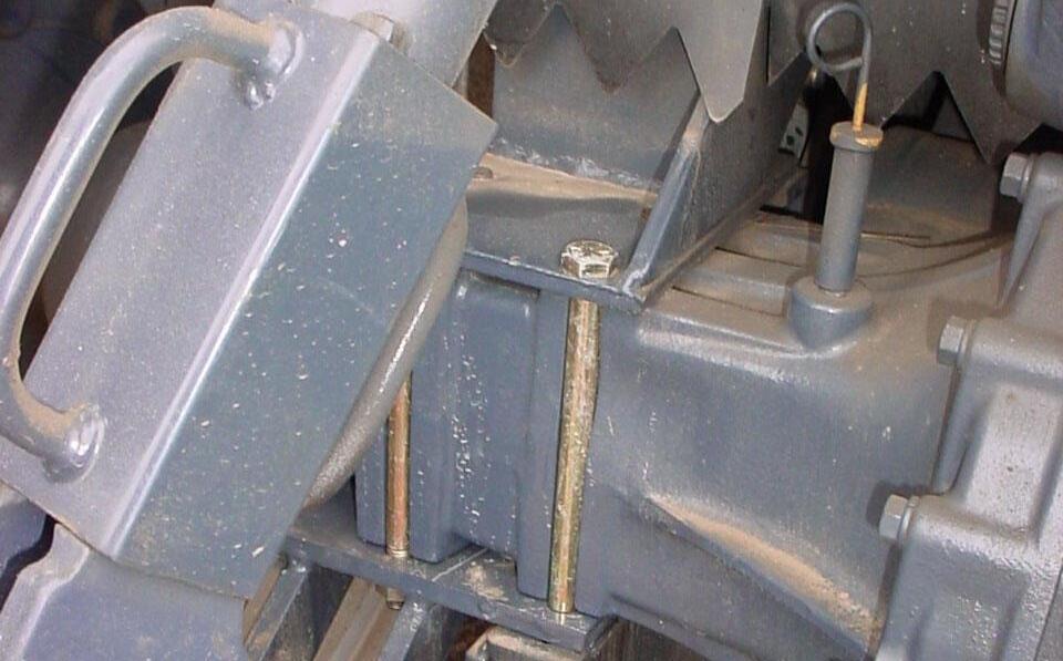
3.2.7. From rear axle, remove inside set of bolts and lockwashers securing 3-point components to rear axle. Save hardware.
Position of bolts to be removed one on each side of axle.
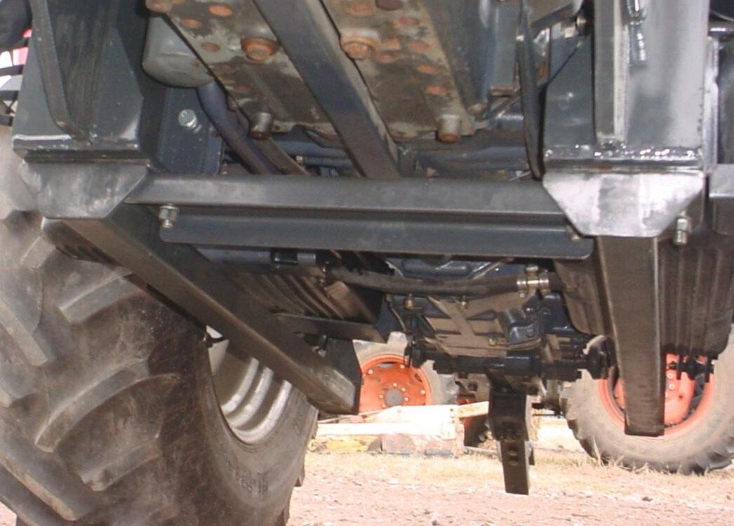
3.2.8. Install rear rail to center bracket using 5/8" x 1-3/4" hex bolts Grade 5, lockwashers, and hex nuts, 2 places outside only.
5/8" x 1-3/4" Hex Bolt Grade 5, 5/8" Lockwasher, and 5/8" Hex Nut. 2 places outside only.
Rear Rail
3.2.9. Install rear rail to rear axle as shown re-using bolts and lockwashers just removed along with 1/2" flatwashers included with mounting kit.
Position of bolts previously removed.
Tractor Bolt and Lockwasher along with Mounting Kit 1/2" Flatwasher, 2 places each side
Rear Rail, 1 place each side
3.2.10. Remove hoist from center bracket.
3.2.11. Install opposite brackets using previous instructions.
3.2.12. Install crossbrace to RH and LH center brackets using 5/8" x 2" hex bolts Grade 5, lockwashers, flatwashers, and hex nuts, 2 places Inside only.
RH Center Bracket
5/8" x 2" Hex Bolt Grade 5, 5/8" Lockwasher, and 5/8" Hex Nut, 2 places each side inside only
RH Rear Rail
Crossbrace
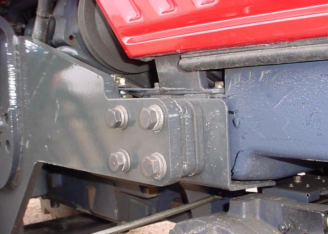
3.2.13. Reference Photo: 5/8" x 1-3/4" hardware, securing rear rail to center bracket is located in outside 2 holes. 5/8" x 2" hardware, securing crossbrace and rear rail to center bracket is located in inside 2 holes.
RH Rear Rail
Crossbrace
5/8" x 2" hardware, inside 2 holes each side
LH Rear Rail
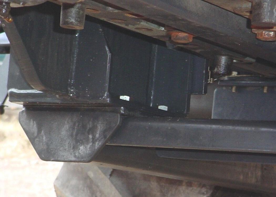
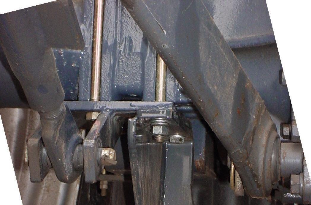
5/8" x 1-3/4" hardware, outside 2 holes each side
NOTE: Do not tighten any of the crossbrace hardware until all other mounting bracket hardware is torqued to specifications.
CRITICAL: Torque all mounting kit hardware.
A. Identify hardware size and grade.
B. Refer to Torque Chart, page 78 and find correct torque for your hardware size and grade.
C. Torque hardware to this specification unless otherwise specified.
IMPORTANT NOTE: To keep mounting kit hardware from loosening during loader operation, hardware must be torqued to specifications.
Center Bracket RH
5/8" x 1-3/4" Hex Bolt, Lockwasher, and Hex Nut, 2 places each side.
16mm x 2.0P x 30mm Hex Bolt Grade 8.8 and 5/8" Lockwasher, 4 places each side.
5/8" x 2" Hex Bolt, Lockwasher, and Hex Nut, 2 places each side.
5/8" x 2" Hex Bolt, Lockwasher, and Hex Nut, 2 places each side.
Center Bracket LH
16mm x 2.0P x 30mm Hex Bolt Grade 8.8 and 5/8" Lockwasher, 4 places each side.
5/8" x 1-3/4" Hex Bolt, Lockwasher, and Hex Nut 2 places each side.
Rear Rail RH
Crossmember
Oscillation Stop LH
1/2" 4-Hole Spacer
Oscillation Stop RH
16mm x 2.0P x 90mm Hex Bolt Grade 10.9, 5/8" Lockwasher, and 5/8" Hardened Flatwasher, 4 places each side.
16mm x 2.0P x 90mm Hex Bolt Grade 10.9, 5/8" Lockwasher, and 5/8" Hardened Flatwasher, 4 places each side.
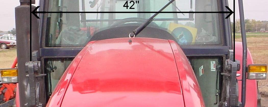
3.2.14. Verify outside surface of brackets are level and the centerline measurement from RH to LH towers reads 42" plus or minus 3/8".
1/2" Hardened Flatwasher plus Tractor Hardware, 2 places each side.
Rear Rail LH