14 minute read
4. PRE-OPERATION INSTRUCTIONS


4.1. HYDRAULIC FLUID
Check the tractor hydraulic fluid level and fill, if required.
4.2. INITIAL LOADER OPERATION
NOTE: If any loader cavitation is noticed during loader operation, check tractor hydraulic fluid level and correct.
NOTE: Keep engine speed at low idle during the initial loader operation.
CAUTION: Escaping hydraulic fluid under pressure can have sufficient force to penetrate skin, causing serious personal injury. Before disconnecting lines, be sure to relieve all pressure.
Before applying pressure to system, be sure all connections are tight and that lines, tubes, and hoses are not damaged.
Fluid escaping from a very small hole can be almost invisible. Use a piece of cardboard or wood, rather than hands, to search for suspected leaks.
If injured by escaping fluid, see a doctor at once. Serious infection or reaction can develop if proper medical treatment is not administered immediately.
4.3. EXTERNAL LOADER VALVE
CAUTION: When properly installed, the loader valve handle will control loader hydraulic circuits as described below.
IMPORTANT: Contaminants in hydraulic fluid can cause valve spools to stick. BE ALERT when operating loader and follow your tractor Operator Manual hydraulic fluid maintenance schedule.
4.4.
LOADER MOUNTED VALVE EQUIPPED WITH SINGLE HANDLE CONTROLLER
On A Loader Not Equipped With Hydraulic Self Level Option
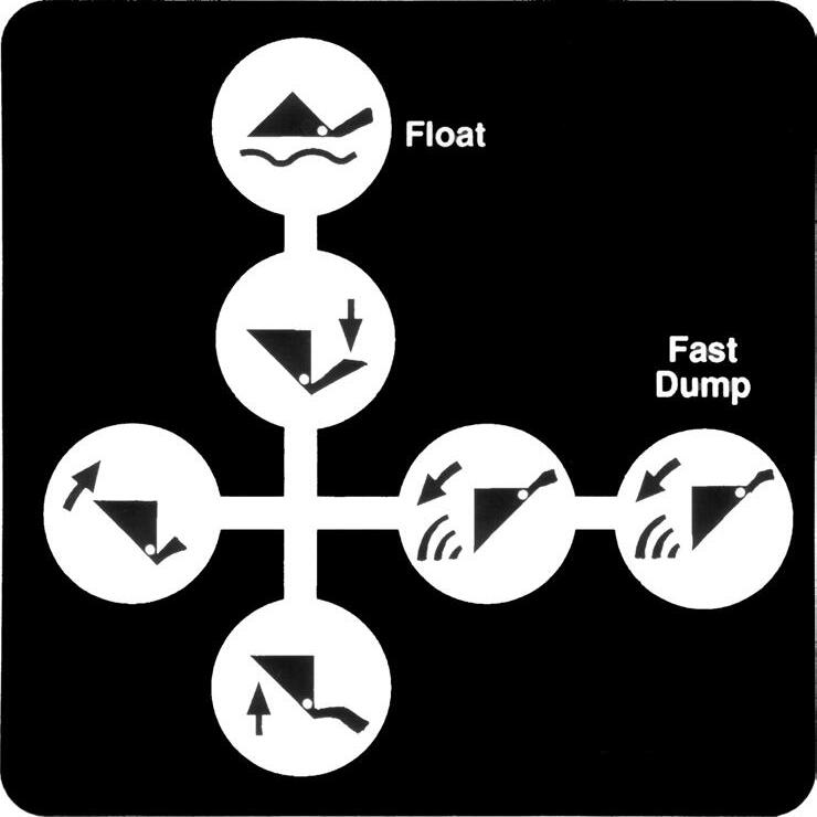
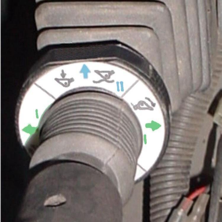
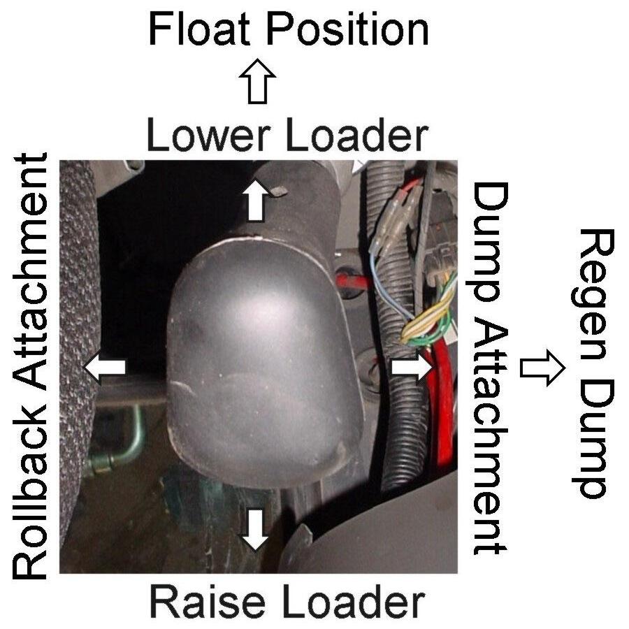
4.4.1. LOADER WITHOUT SELF LEVEL VALVE: Your loader utilizes a loader mounted valve equipped with single handle control and it will function as described.
Number 3 Position: Push the handle full forward to activate float position.
Number 2 Position: Push the handle forward to lower loader.
Number 1 Position: Pull the handle back to raise loader.
Decal Operation Illustration
Number 5 Position: Push the handle outward to dump attachment.
Number 6 Position: Push the handle full outward to activate regen position which will dump attachment at a faster rate.
Number 4 Position: Pull the handle inward to roll back attachment.
4.5. NEUTRAL POSITION
The loader external valve has a "neutral position" which prevents movement of the loader or attachment. When the valve handle is manually released from the work position, the valve spool will return to the neutral position.
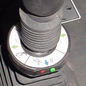
4.6. NEUTRAL LOCK POSITION
Push collar down to lock controller into neutral position — Red button is out when neutral position is locked. Lift collar up to unlock controller from neutral position — Green button is out when neutral position is unlocked.
4.7. FLOAT POSITION
The loader valve has a "float position" incorporated into the lift cylinder circuit which allows the loader to float. This float feature is important for satisfactory operation when scraping, sweeping, leveling, or any job where it is necessary to follow the contour of the surface. To activate float position, lower the bucket or attachment and push the valve handle all the way forward into detent. The valve will stay in float detent position until the operator manually pulls the valve handle out of detent position to deactivate float.
4.8. REGENERATIVE DUMPING POSITION
The loader valve has a "Feel Position Regenerative Spool" incorporated in the attachment spool. The tilt cylinders must be connected to this spool allowing the operator to choose normal dump or fast dump during loader operation.
NOTE: Use normal dump position when digging with loader. This will allow operator to put full tractor weight on cutting edge during this operation. The regenerative function can then be used when dumping load from bucket.
NOTE: Valve circuits must be hooked up correctly to allow regen to operate correctly.
IMPORTANT: If the bucket or attachment does not operate as indicated on the directional decal, lower the bucket to the ground, stop the engine, and relieve all hydraulic pressure. Recheck hydraulic circuits hookup to loader valve and correct.
NOTE: Use of regen function during dumping will eliminate attachment cylinder cavitation, which will reduce or eliminate any free movement of bucket or attachment during loader operation.
CAUTION: Do not tamper with relief valve setting. The relief valve is pre-set at the factory. Changing the setting can cause overloading of the loader and tractor, which may result in serious injury.
4.9. INITIAL LOADER OPERATION
NOTE: Keep engine speed at low idle during the initial loader operation. Before operating the loader, fully raise and lower the boom two or three times. Then raise the loader bucket approximately four (4) feet above the ground and cycle the tilt cylinders two or three times. Lower the bucket or attachment to the ground. Check the tractor hydraulic fluid level and fill as required. Refer to the tractor Operator Manual for the proper hydraulic fluid and the correct hydraulic fluid level.
CAUTION: Before leaving the tractor seat, lower attachment or loader boom to ground, stop engine, lock brakes, relieve hydraulic pressure, and remove key.
IMPORTANT: Always keep the cylinders in a retracted position when the loader is not in use to guard against rust and contamination which may cause damage to the cylinder rods and hydraulic system.
4.10. REMOVING AIR FROM HYDRAULIC SYSTEM
Repeat raising and lowering the loader boom and bucket until all the air is removed from the system and the system responds properly. Check the tractor hydraulic fluid level and fill, if required.
4.11. RELIEF NOISE
When operating loaders at high RPMs with orifice installed in attachment circuit, some hydraulic oil will go over pressure relief. This could cause some relief noise from relief cartridge, which is normal.
5. DAILY MAINTENANCE & LUBRICATION
5.1. DAILY CHECKS
5.1.1. Check all hardware daily before operation. Tighten hardware to torque values as specified in the Torque Chart, page 78 unless otherwise specified.
IMPORTANT NOTE: To prevent mounting kit hardware from loosening during operation always torque mounting kit hardware to specified torque noted in Loader Operator Manual. Check bolt torque every 50 hours of loader operation.
5.1.2. With the engine off and the bucket on the ground, inspect all hoses for cuts or wear. Check for signs of leaks and make sure all fittings are tight.
CAUTION: Escaping hydraulic fluid under pressure can have sufficient force to penetrate skin, causing serious personal injury. Before disconnecting lines, be sure to relieve all pressure.ıBefore applying pressure to system, be sure all connections are tight and that lines, tubes, and hoses are not damaged.ıFluid escaping from a very small hole can be almost invisible. Use a piece of cardboard or wood, rather than hands, to search for suspected leaks.ıIf injured by escaping fluid, see a doctor at once. Serious infection or reaction can develop if proper medical treatment is not administered immediately.
5.1.3. Service your loader at the intervals and locations as specified. When you service your loader, use only high quality lubricants. The engine hour meter on the tractor shows the amount of hours the engine has worked. Use the hour meter to service your loader at the correct time periods.
IMPORTANT: Lower the loader boom to the ground and relieve pressure in loader hydraulic lines prior to doing any service or maintenance operations on the tractor or loader. Check the tractor hydraulic fluid level as specified in the tractor Operator Manual.
NOTE: When checking hydraulic system fluid level, the loader boom must be on the ground with the bucket or attachment resting flat on a level surface.
5.2. LOADER LUBRICATION
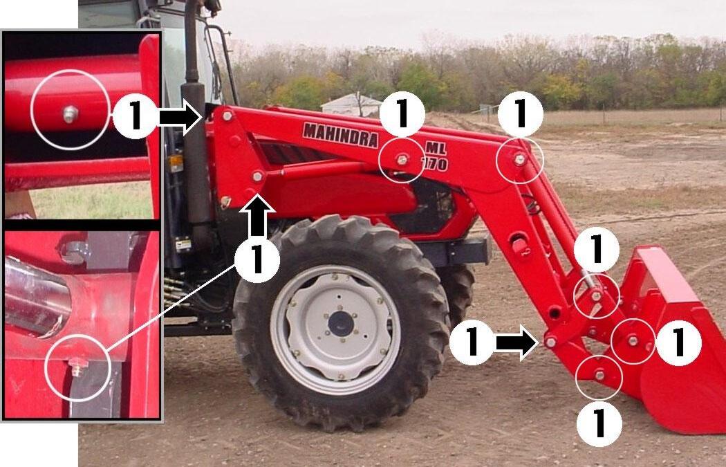
5.2.1. There are 16 grease fittings on this loader, one at each pivot. Lubricate pivots as specified.
CAUTION: Do not stand, walk, or work under a raised loader or attachment unless it is securely blocked or held in position. Accidental movement of the valve handle/handles or leaks in the hydraulic system could cause the loader to drop, or attachment to dump, causing severe injury.
5.2.2. Lower loader boom until bucket or attachment rests on ground, and relieve all hydraulic pressure before lubricating.
(1) Lubricate these 16 pivot points every 10 hours of operation.
NOTE: Lift Cylinder Rod End Grease Zerk must face downward.
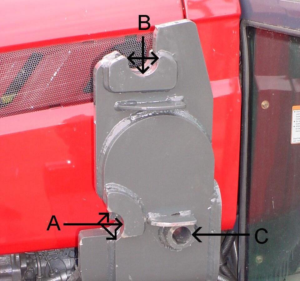
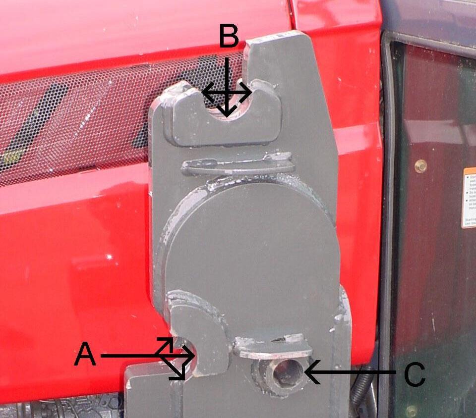
5.2.3. During initial setup, and as required; apply a small amount of grease to each tower in areas of tower bottom receiver (A), tower top receiver (B), and handle pin bushing (C). This will aid in parking loader.
5.2.4. Before servicing your tractor, always do one of the following. . Park the loader off of the tractor.

CAUTION: Do not stand, walk, or work under a raised loader or attachment unless it is securely blocked or held in position. Accidental movement of valve handle/handles or leaks in the hydraulic system could cause the loader to drop, or attachment to dump, causing severe injury.
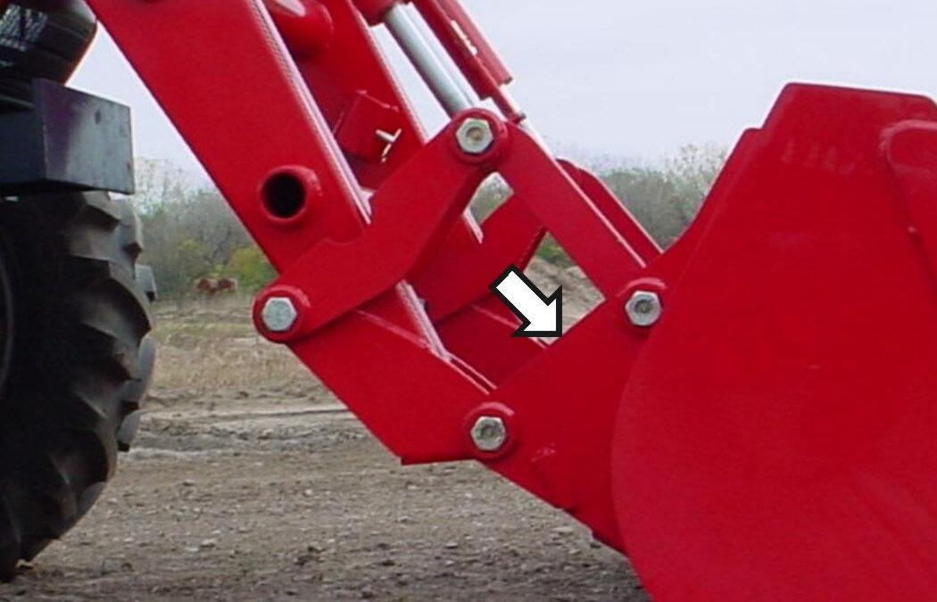
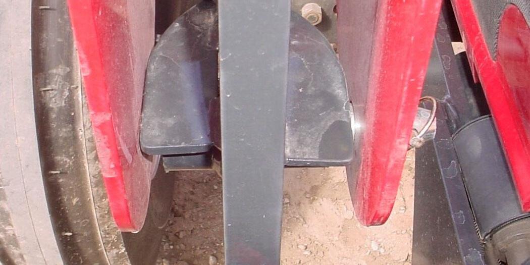
5.2.5. Clean area identified with arrow of all material if build up occurs during operation. This will prevent damage to loader components.
NOTE: Clean this area of all material if build up occurs during operation.
5.3. SERVICE AREAS
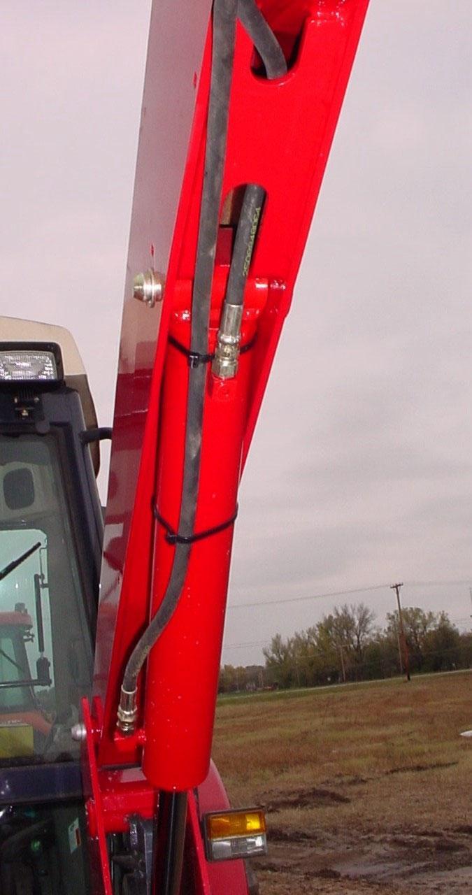
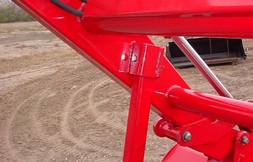
5.3.1. RH SIDE SERVICE NOTE: If a lift cylinder hose is replaced, always locate and secure hose as shown in photo to prevent hose from being pinched between loader and cylinder causing damage to hose.
RH Lift Cylinder Base End Hose
RH Lift Cylinder Rod End Hose
Nylon Ties
NOTE: Route hoses so they either do not contact notch area or they only rest against notch area. Do not twist hoses so they are pulled against notch area.
5.3.2. LH SIDE SERVICE NOTE: If a lift cylinder hose is replaced, always locate and secure hose as shown in photo to prevent hose from being pinched between loader and cylinder causing damage to hose.
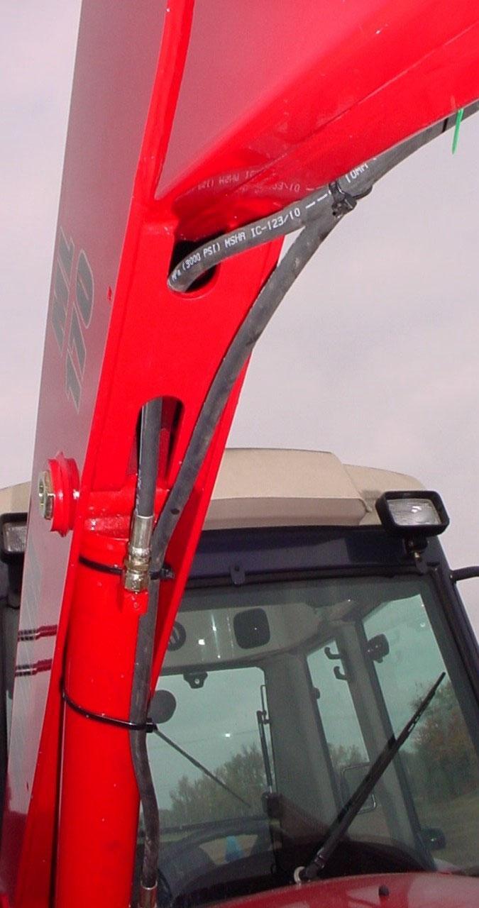
LH Lift Cylinder Rod End Hose
LH Lift Cylinder Base End Hose
Nylon Ties
6. OPERATING INSTRUCTIONS
The loader should be operated with the tractor engine running from 1700 to 2200 rpm. Excessive speeds are dangerous, and may cause bucket spillage and unnecessary strain on the tractor and loader. When operating in temperatures below 30oF, run the tractor engine below 1200 rpm until the hydraulic fluid temperature exceeds 30oF. The following text and illustrations offer suggested loader and tractor operating techniques.
6.1. FILLING THE BUCKET
Approach and enter the pile with a level bucket. Then rollback and lift the bucket.
The rollback and lifting of the bucket will increase efficiency because a level bucket throughout the lifting cycle resists bucket lift and increases breakaway effort. NOTE: Do not be concerned if the bucket is not completely filled during each pass. Maximum productivity is determined by the amount of material loaded in a given period of time. Time is lost if two or more attempts are made to fill the bucket on each pass.
6.2. LIFTING THE LOAD
When lifting the load, keep the bucket positioned to avoid spillage.
CAUTION: Do not attempt to lift bucket or attachment loads in excess of the loader capacity.
6.3. CARRYING THE LOAD
Position the loader in a low position when transporting a loaded or empty bucket or attachment. Use extreme care when operating the loader on a slope. Keep the bucket as low as possible. This keeps the bucket and tractor center of gravity low and will provide maximum tractor stability.
CAUTION: Operating the loader on a hillside is dangerous and is not recommended.
When transporting a load, keep the bucket as low as possible to avoid tipping, in case a wheel drops in a rut.
6.4. DUMPING THE BUCKET
Lift the bucket just high enough to clear the side of the vehicle. Move the tractor in as close to the side of the vehicle as possible, then dump the bucket.
6.5. LOWERING THE BUCKET
After the bucket is dumped, back away from the vehicle while lowering and rolling back the bucket.
6.6. OPERATING WITH FLOAT CONTROL
During operation on hard surface, keep the bucket level and position the lift control in the float position to permit the bucket to float on the work surface.ıIf hydraulic down pressure is exerted on the bucket, the cutting edge will wear faster than normal.
The float position will also avoid mixing of surface material with stockpile material. The float position will reduce the chance of surface gouging while removing snow or other material, or when working with a blade.
6.7. LOADING FROM A BANK
Choose a forward gear that provides a safe ground speed and power for loading.
CAUTION: Exercise caution when undercutting high banks. Dirt slides can be dangerous. Load from as low as possible for maximum efficiency. Loader lift and breakaway capacity diminish as loading height is increased.
Side cutting is a good technique for cutting down a big pile.
If the pile sides are too high and liable to cause cave-in, use the loader to break down the sides until a slot can be cut over the top.
Another method for large dirt piles is to build a ramp approach to the pile.
It is important to keep the bucket level when approaching a bank or pile. This will help avoid gouging the work area.
6.8. PEELING AND SCRAPING
Use a slight bucket down angle, travel forward, and hold the lift control forward to start the cut. Make a short cut and breakout cleanly.
With the bucket level, start a cut at the notch approximately 2 in. deep. Hold the depth by feathering the tilt control to adjust the cutting edge up or down. When the front tires enter the notch, adjust the lift cylinder to maintain proper depth.
Make additional passes until the desired depth is reached. During each pass, use only the tilt control while at working depth. This will allow you to concentrate on controlling the bucket angle to maintain a precise cut.
6.9. LOADING LOW TRUCKS OR SPREADERS FROM A PILE
For faster loading, minimize the angle of turn and length of run between pile and spreader.
Back grade occasionally with a loaded bucket to keep the work surface free of ruts and holes. Also, hold the lift control forward so the full weight of the bucket is scraping the ground. Use the heel of the bucket.
6.10. BACKFILLING
Approach the pile with the bucket flat.
Poor operating methods actually move no more dirt and make it more difficult to hold a level grade. Do not use the bucket in the dumped position for bulldozing. This method will impose severe shock loading on the dumplinkage, the tilt cylinders, and the tractor.
Leave dirt in the bucket because dumping on each pass wastes time.
Operate at right angles to the ditch, taking as big a bite as the tractor can handle.
Leave dirt that drifts over the side of the bucket for final clean up.
Pile dirt on the high side for easier backfilling on a slope.
6.11. HANDLING LARGE HEAVY OBJECTS
CAUTION: Handling large heavy objects can be extremely dangerous due to:
• Danger of rolling the tractor over.
• Danger of upending the tractor.
• Danger of object rolling or sliding down the loader boom onto the operator.
CAUTION: If you must perform the above work, protect yourself by:
• Never lifting the load higher than necessary to clear the ground when moving.
• Adding rear ballast to the tractor to compensate for the load.
• Never lifting large objects with equipment that does not have an anti-rollback device.
• Moving slowly and carefully; avoiding rough terrain.
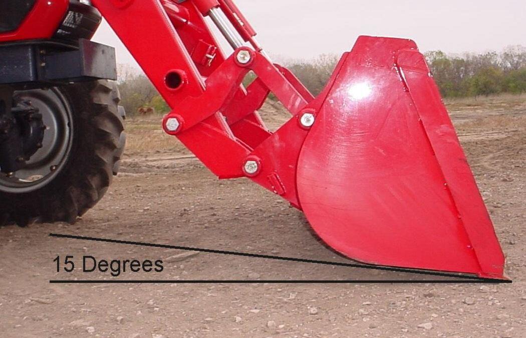
6.12. BACK GRADING
When back grading, the angle between the bottom of the bucket and the ground must not be more than 15 degrees. Failure to follow these instructions could cause loader tilt cylinders to fail and void warranty.
7. DISMOUNTING THE LOADER
CAUTION: Always park loader with material bucket attached to the loader.
CAUTION: Before leaving the tractor seat, lower attachment or loader boom to ground, stop engine, lock brakes, relieve hydraulic pressure, and remove key.
CAUTION: Do not stand, walk, or work under a raised loader or attachment unless it is securely blocked or held in position. Accidental movement of valve handle/handles or leaks in the hydraulic system could cause the loader to drop, or attachment to dump, causing severe injury.
CAUTION: Do not allow bystanders in loader work area.
IMPORTANT: Never allow weight of tractor to be placed on parking stands when mounting or dismounting loader.
7.1.1. Position the loader on a hard level surface. The more level the surface the easier the loader is to mount and dismount.
7.1.2. Raise loader, dump bucket over, and then lower loader so that bucket cutting edge is approximately 1/2" off of ground.
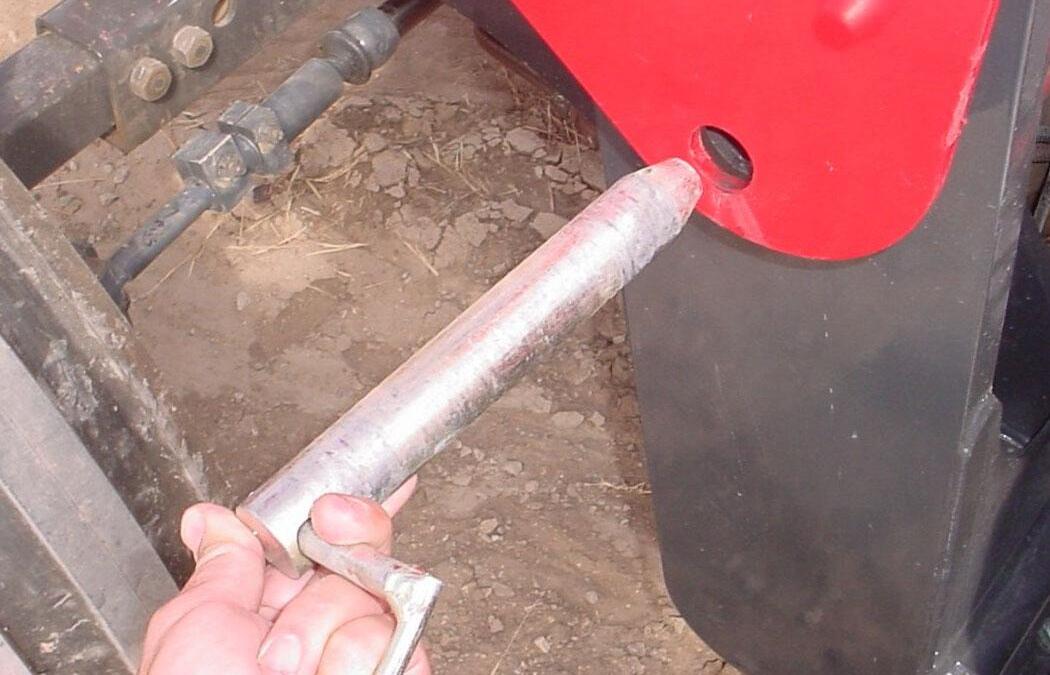
7.1.4. Remove snap pins from handle pins located in bearing boxes.
Bearing Box
Handle Pin Snap Pin
7.1.5. Remove handle pins from bearing boxes. Bearing Box
Handle Pin
7.1.6. Remove parking stands from storage positions in the boom crosstubes. Return hairpin cotters to storage positions.
Hairpin Cotter in Storage Position.
Parking Stand in Storage Position.
7.1.7. Position parking stands in attaching brackets on inside of each boom arm. Secure using clevis pins and hairpin cotters.
Clevis Pin and Hairpin Cotter in Park Position.

Attaching Bracket.
Parking Stand in Park Position.
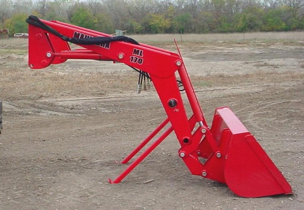
7.1.8. Make sure long end of parking stand is located toward rear end of tractor. Photo shows parking stands in park position and loader ready to be dismounted.

Parking Stands in Park Position with long end of stands positioned rearward.
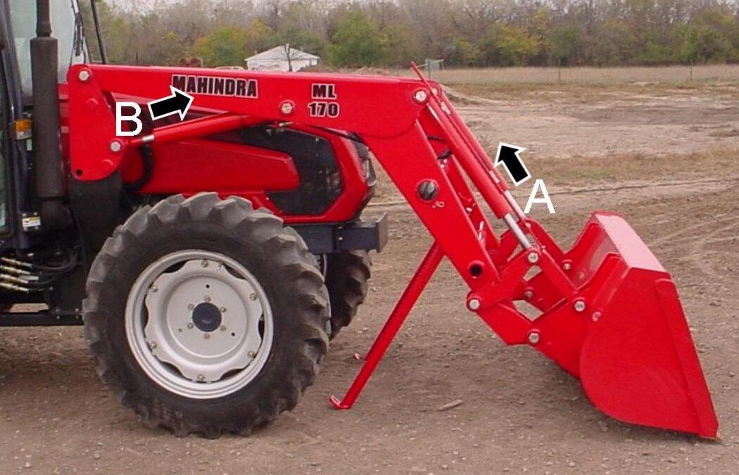
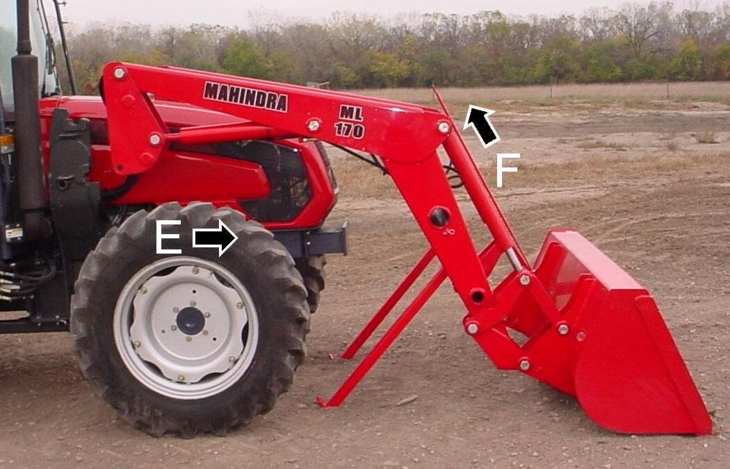
7.1.9. Retract tilt cylinders (A) to roll bucket back and retract lift cylinders (B) to lower loader boom down until parking stands make firm contact with ground.
NOTE: Driving the tractor forward slowly while positioning loader will allow parking stands to contact ground firmly.
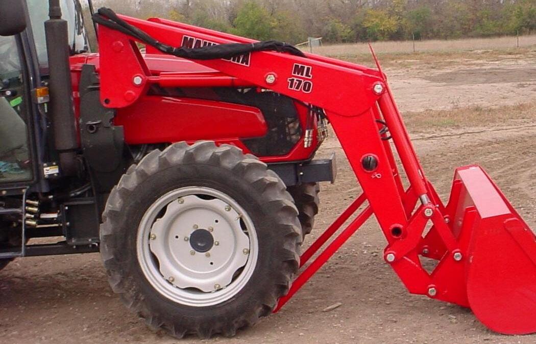
Parking Stands contacting ground firmly. Bucket resting on ground.
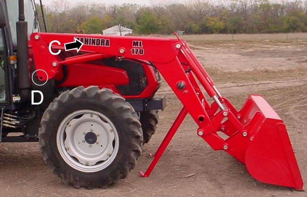
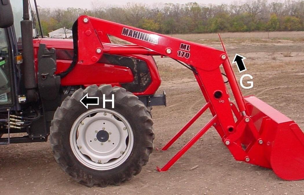
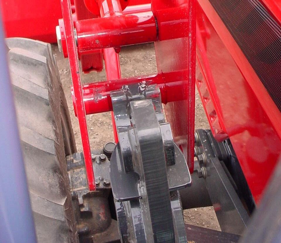
7.1.10. Retract lift cylinders (C) until bearing box pins (D) lift out of tower hooks and clear towers.
7.1.11. Slowly drive tractor forward while (E) retracting tilt cylinders (F). Doing this will allow towers to guide loader as it is being parked off of tractor. This will allow loader to be held in position to clear exhaust during dismounting.
7.1.12. Retract tilt cylinders (G) until bucket is level on ground.
7.1.13. Make sure all loader components clear tractor. Back tractor away (H) slightly.
7.1.14. Stop the tractor engine and then work valve handle/handles to relieve hydraulic fluid pressure in lines. Refer to tractor operator manual for additional information.
7.1.15. Reinstall handle pins and snap pins to bearing boxes for storage.
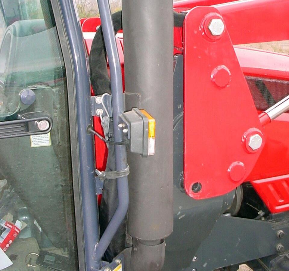
7.1.16. Return rubber strap to RH Cab hand rail for storage.
7.1.17. Disconnect loader hoses from quick couplers.
7.1.18. Start tractor and slowly back tractor away from the loader.
IMPORTANT: To avoid hydraulic hose damage, be alert and make sure hoses do not catch on tractor and/or loader during mounting or dismounting.
WARNING: Make sure parked loader is on a hard level surface. Engage all safety devices to prevent loader from falling and being damaged or injuring someone. Do not repair loader if it is not mounted on the tractor. Loss of hydraulic fluid or removal of parts could cause loader to collapse resulting in injury.
8. MOUNTING THE LOADER
CAUTION: Do not stand, walk, or work under a raised loader or attachment unless it is securely blocked or held in position. Accidental movement of valve handle/handles or leaks in the hydraulic system could cause the loader to drop, or attachment to dump, causing severe injury.
CAUTION: Do not allow bystanders in loader work area.
IMPORTANT: Never allow weight of tractor to be placed on parking stands when mounting or dismounting loader.
8.1.1. To aid in mounting and dismounting loader, apply a small amount of grease, if needed, to each tower in areas of tower bottom receiver (A), tower top receiver (B), and handle pin bushing (C).
Tower
8.1.2. Remove handle pins and snap pins from bearing boxes.
8.1.3. Slowly drive tractor forward to a position where the hoses can be connected to the quick couplers.
8.1.4. Stop the engine. Connect the loader hydraulic hoses to the correct quick couplers.
8.1.5. Route loader hoses away from exhaust between exhaust and cab.
8.1.6. Check that lift cylinders are fully retracted. Then drive tractor forward. Use tilt cylinders to position height of bearing box top pin making sure all loader components clear all tractor components.
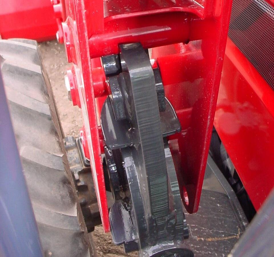
8.1.7. Align bearing box top pin with tower top receiver guide post, both sides. Make sure loader is centered right to left on both towers.
Bearing Box Top Pin
Tower Top Receiver Guide Post Tower Top Receiver Tower Bottom Receiver
Tower
8.1.8. Extend lift cylinders (A) slowly making sure loader seats completely in tower top receivers (B) and tower bottom receivers (C).

8.1.9. Extend tilt cylinders (D) until bucket is rolled over 90o. Adjust lift cylinder so bucket is approximately 1/2" off ground.
8.1.10. Secure loader to mounting brackets as follows. Bucket positioned 1/2" off ground.
8.1.11. Reinstall handle pins to bearing boxes and secure using snap pins.
Bearing Box
Handle Pin and Snap Pin
8.1.12. Remove parking stands from parked position. Return clevis pins and hairpin cotters to attaching brackets for storage.
Clevis Pin and Hairpin Cotter in Park Position.
Attaching Bracket. Parking Stand in Park Position.
Bearing Box
Bearing Box Bottom Pin
Bearing Box
Centered Right to Left on Tower
8.1.13. Return parking stands to storage positions in the boom crosstubes. Secure using hairpin cotters.
Hairpin Cotter in Storage Position.
Parking Stand in Storage Position.
8.1.14. Remove rubber strap from RH cab hand rail.
8.1.15. Route hoses away from tractor exhaust.
Loader Hoses (route toward center of tractor)
Tractor Exhaust
8.1.16. Route hoses to RH side of tractor cab as shown. Secure hoses to cab hand rail using rubber strap.
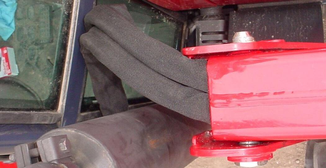
Tractor Exhaust
Loader Hoses
RH Tractor Cab Hand Rail
Rubber Strap secured to Cab Hand Rail

Rubber Strap wrapped around Tractor Hoses
IMPORTANT: To avoid hydraulic hose damage, be alert and make sure hoses do not catch on tractor and/or loader during mounting or dismounting.