10 minute read
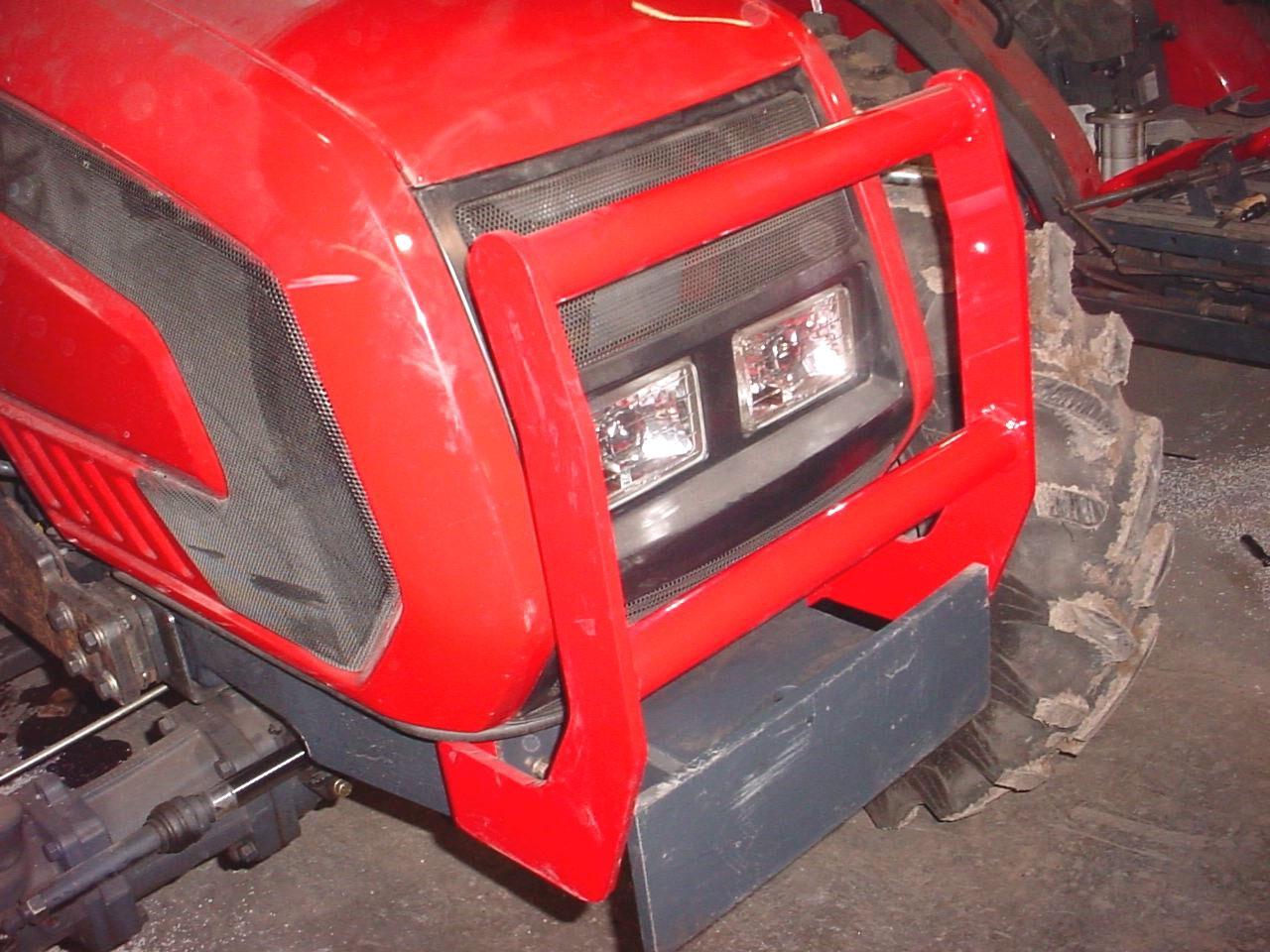
9. OPTIONAL GRILL GUARD


9.1. INSTALLATION INSTRUCTIONS
9.1.1. Attach grill guard to front of tractor. Secure re-using tractor hardware.
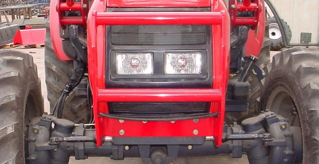
Grill Guard. Tractor Hardware, 6 places.
9.1.2.
Grill Guard
Weight Frame
10. PIN ON BUCKET
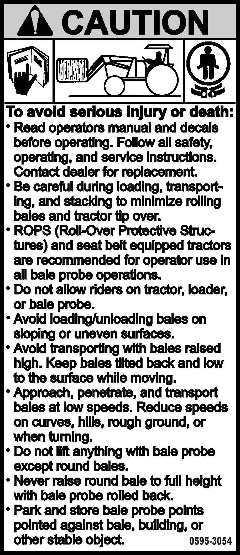
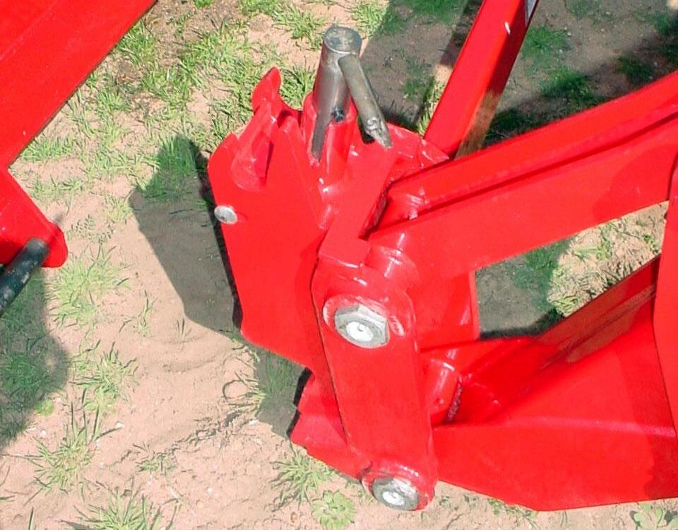
IMPORTANT: Read safety information in this section and on decals before operating attachments.
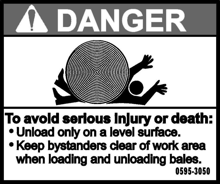
WARNING: To avoid serious injury or death from large round or square hay bale handling:
• Use only Factory bale spear or bale retaining device handler attachment when handling round bales.
• Do not handle large square bales without a retaining device handler attachment
• Do not use buckets, forks, or other attachments without bale retaining devices.
• Do not use loader for handling large, heavy objects such as logs, tanks, etc.
WARNING: To avoid serious injury or death, realize handling large heavy objects can be extremely dangerous due to:
• Danger of rolling the tractor over.
• Danger of upending the tractor.
• Danger of the object rolling or sliding down the loader arms onto the operator.
WARNING: To avoid serious injury or death:
• Do not lift or carry anyone on buckets, forks, probes, or any other portion of the loader or loader attachments.
• Avoid contact with electrical power lines by loader or attachment
WARNING: Inadvertent movement of the loader or attachment could result in serious injury or death.
10.1. INSTALLATION INSTRUCTIONS TO PIN ON QUICK ATTACH
IMPORTANT: Refer to Pages 55 to 57 for instructions concerning Installing Attachment to Pin On Quick Attach.
IMPORTANT: Refer to Page 58 for instructions concerning Removing Attachment from Pin On Quick Attach.
10.2. INSTALLATION INSTRUCTIONS DIRECT TO LOADER
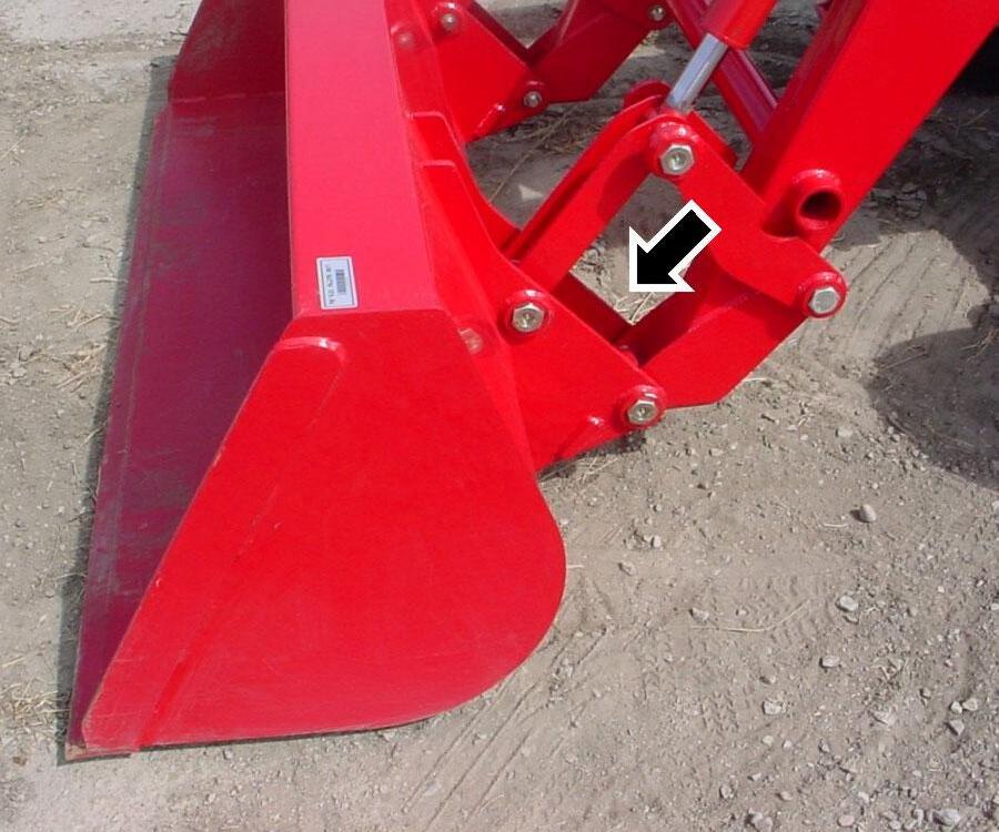
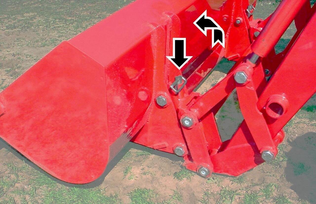
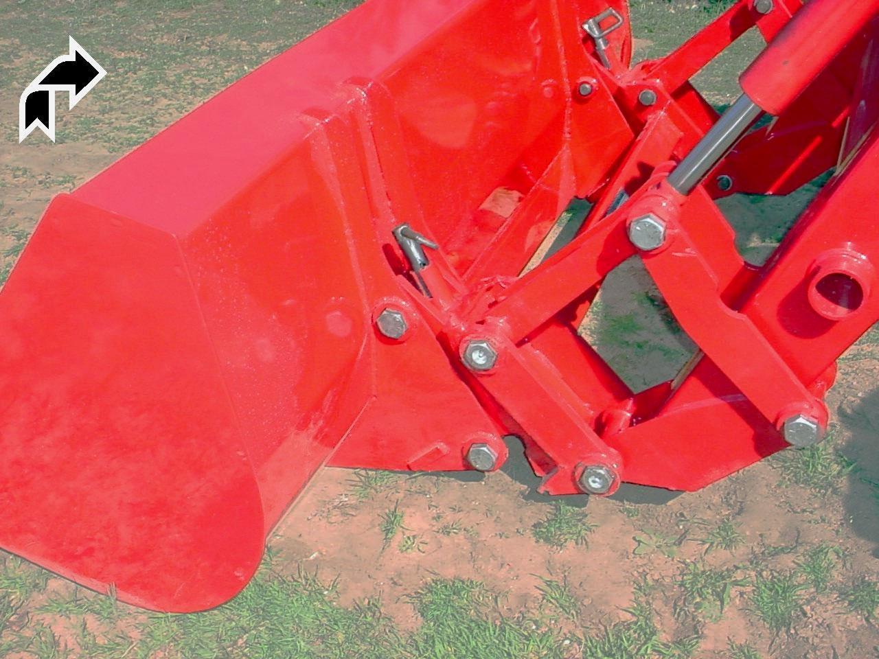
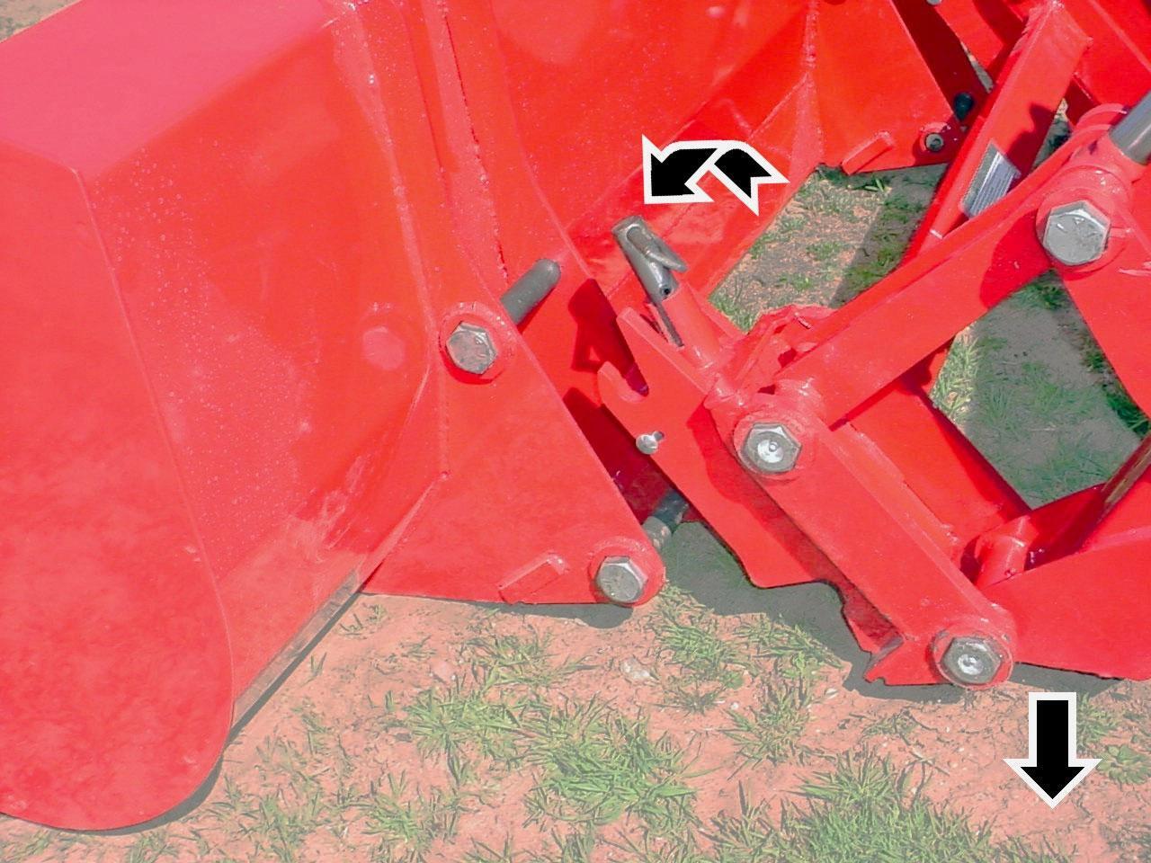
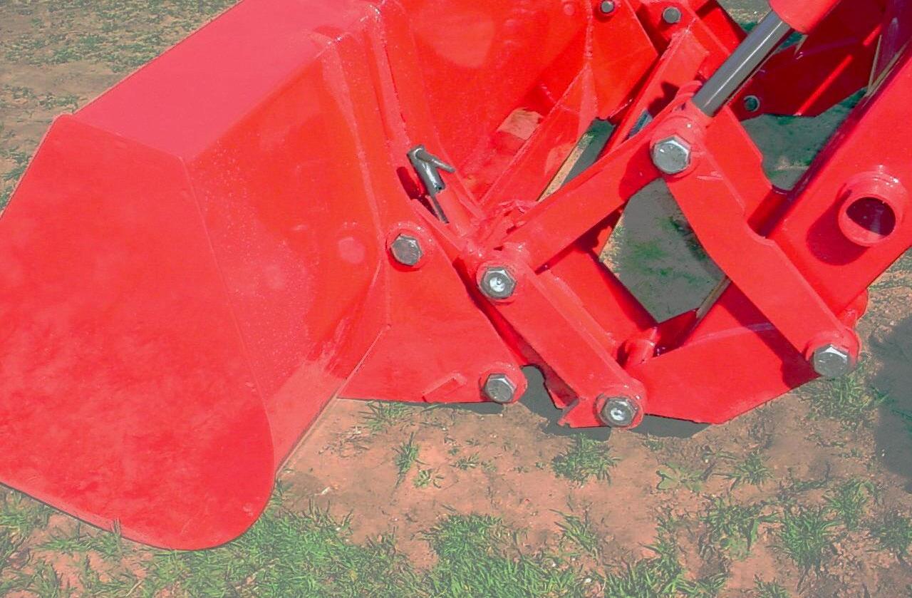
10.2.1. Install pin on bucket direct to loader. Secure using pins and e-clips.
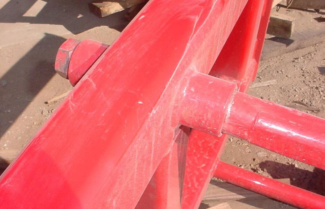
NOTE: Clean arrow area of all material if build up occurs during operation.
Bottom Pin 1-1/8" x 7.01" and E-Clip, 1 place each side.
Top Pin 1-1/8" x 7.01" and E-Clip, 1 place each side.
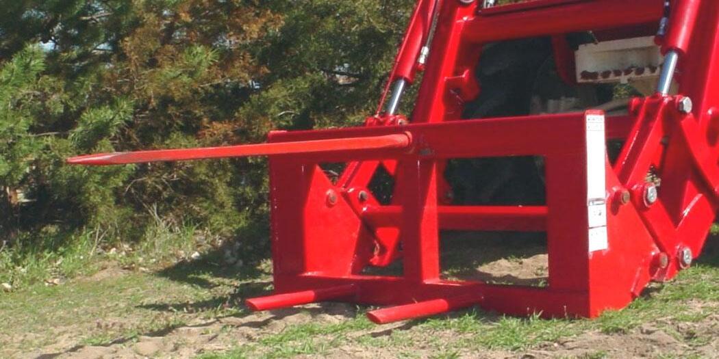
11. PIN ON BALE SPEAR
IMPORTANT: Read safety information in this section and on decals before operating attachments.
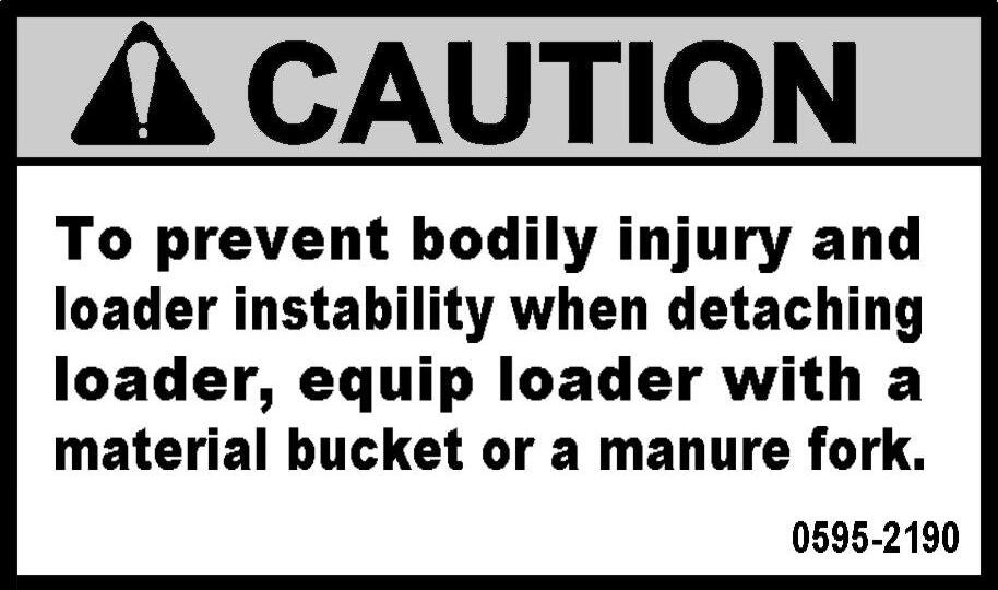
IMPORTANT: It is not recommended that loader be detached with bale spear attached. Loaders will park safely; however, bale spear could be damaged during parking. Always detach loader with bucket or other loader Factory approved attachment attached.
CAUTION: When transporting a round bale, tilt the bale spear slightly back from level and carry the load in a low position.
CAUTION: Never raise round bale to full height with bale spear rolled back as serious injury or death could occur.
CAUTION: To prevent bodily injury, park and store bale spear with points pointed against bale, building, or other stable object.
11.1. PIN ON BALE PROBE
IMPORTANT: This spear is a high strength alloy – drop forged steel and should not be welded or heattreated.
IMPORTANT: Maximum load limit on super penetrator bale spear is 2,000 pounds.
11.2. ASSEMBLY INSTRUCTIONS
11.2.1. Install Bale Spear into tapered sleeve and secure with nut. Torque nut 515 ft. lb. Failure to follow these instructions could cause damage to spear and void your warranty.
(1) Upper Spear.
Flat surface of spear located upward.
(2) Tapered Sleeve.
(3) Upper Spear Nut, 28mm. Torque nut to 515 ft. lb.
11.3. INSTALLATION INSTRUCTIONS TO PIN ON QUICK ATTACH
IMPORTANT: Refer to Pages 55 to 57 for instructions concerning Installing Attachment to Pin On Quick Attach.
IMPORTANT: Refer to Page 58 for instructions concerning Removing Attachment from Pin On Quick Attach.
11.4. INSTALLATION INSTRUCTIONS DIRECT TO LOADER
11.4.1. Install pin on bale spear direct to loader. Secure using pins and e-clips.
Top Pin 1-1/8" x 7.01" and E-Clip, 1 place each side.
Bottom Pin 1-1/8" x 7.01" and E-Clip, 1 place each side.
11.5. OPERATING INSTRUCTIONS
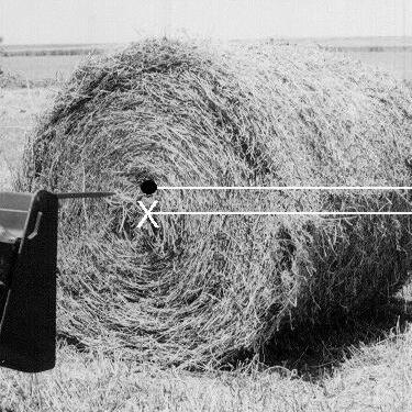
11.5.1. With bale spear level with ground, slowly spear bale slightly above center.
11.5.2. With all three spears completely engaged into bale, tilt bale spear slightly back from level and transport the load in a low position. Spear bale slightly above center of bale.
12. PIN ON PALLET FORK
IMPORTANT: Read safety information in this section and on decals before operating attachments.

WARNING: The pallet fork attachment is specifically designed to engage and load palleted materials. Do not use forks to handle large loads such as bales, posts, etc. as they can fall or roll back onto operator causing serious injury or death.
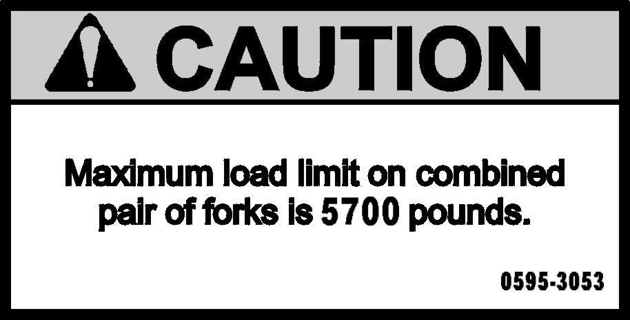
CAUTION: Maximum load limit on combined pair of forks is 5700 pounds.
12.1. PIN ON PALLET FORK
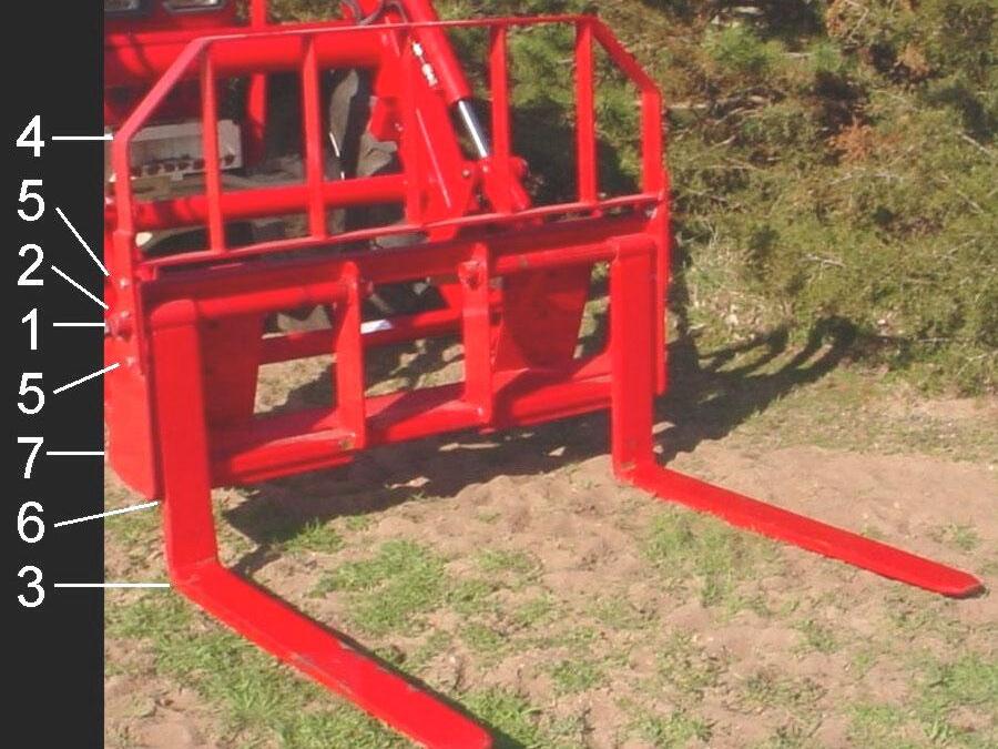
12.1.1. The Pin On Pallet Fork has two tines each 1-1/2" x 4" x 42".
12.2.
Assembly
INSTRUCTIONS
12.2.1. Install (4) guard to (7) pallet fork frame using (5) 1-2" x 1-1/2" bolt, lockwasher, flatwasher, and nut, 2 places each side.
12.2.2. Install (3) forks to (7) pallet fork frame using (1) pins, 2 places secure using (2) 3/8" x 2-1/2" bolts, lockwashers, and nuts, 4 places.
12.2.3. Locate (6) hooks on (3) forks on backside of angle to prevent fork rotation.
12.3. INSTALLATION INSTRUCTIONS PIN ON QUICK ATTACH
IMPORTANT: Refer to Pages 55 to 57 for instructions concerning Installing Attachment to Pin On Quick Attach.
IMPORTANT: Refer to Page 58 for instructions concerning Removing Attachment from Pin On Quick Attach.
12.4. INSTALLATION INSTRUCTIONS DIRECT TO LOADER
12.4.1. Install pin on bale spear direct to loader. Secure using pins and e-clips.
Top Pin 1-1/8" x 7.01" and E-Clip, 1 place each side.
Bottom Pin 1-1/8" x 7.01" and E-Clip, 1 place each side.
12.5. OPERATING INSTRUCTIONS
The operator must keep the load centered and as far back on the forks as possible. Operator must always keep load level. Carry the load low and at a slow speed.
12.6. PARKING INSTRUCTIONS
If parking loader from tractor with pallet fork attachment, move forks outward to widest position (see photo above). NOTE: Move Forks outward to Widest Position
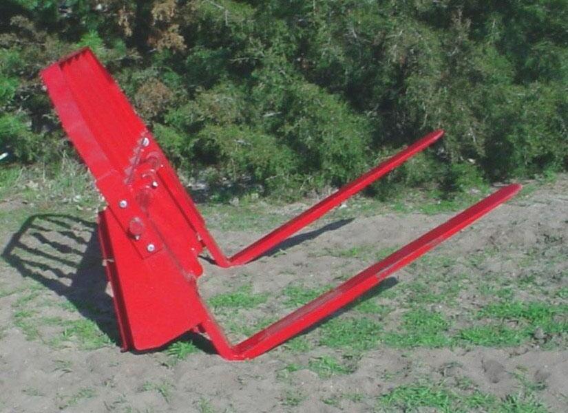
12.7. PARKING STABILITY
If parking pallet fork off of loader, store as shown at right for stability.
13. OPTIONAL PIN ON QUICK ATTACH SYSTEM
IMPORTANT: Read safety information in this section and on decal before operating attachment.
NOTE: Pin On Quick Attach System is optional equipment
WARNING: Always read and follow operating instructions before operating Pin On Quick Attach System.
13.1. RECOMMENDED LOADER FACTORY APPROVED ATTACHMENTS
IMPORTANT: Use only Loader Factory Approved Attachments for mounting on this Pin On Quick Attach System.
13.2. PIN ON QUICK ATTACH
WARNING: Always read and follow operating instructions before operating Pin On Quick Attach System.
13.2.1. Install pin on quick attach direct to loader. Secure using pins and e-clips.
Top Pin
1-1/8" x 7.01" and E-Clip, 1 place each side.
Bottom Pin
1-1/8" x 7.01" and E-Clip, 1 place each side.
14. INSTALLING BUCKET OR ATTACHMENT TO PIN ON QUICK ATTACH
CAUTION: Before leaving the tractor seat, stop the engine and lock brakes when installing or removing bucket or attachment.
CAUTION: Do not stand, walk, or work under a raised loader or attachment unless it is securely blocked or held in position. Accidental movement of valve handle/handles or leaks in the hydraulic system could cause the loader to drop, or attachment to dump, causing severe injury.
14.1. RECOMMENDED LOADER FACTORY APPROVED ATTACHMENTS
14.1.1. Use only the following Loader Factory Approved Attachments for mounting on this Pin On Quick Attach System.
♦ Pin On Bucket 72"
♦ Pin On Bucket 78"
14.2. OPERATING INSTRUCTIONS
♦ Pin On Bucket 84"
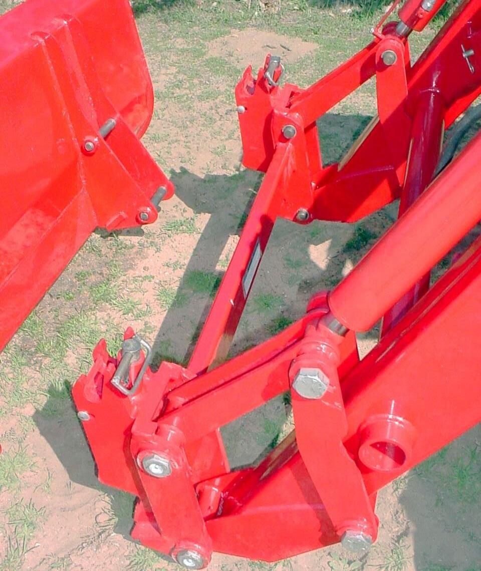
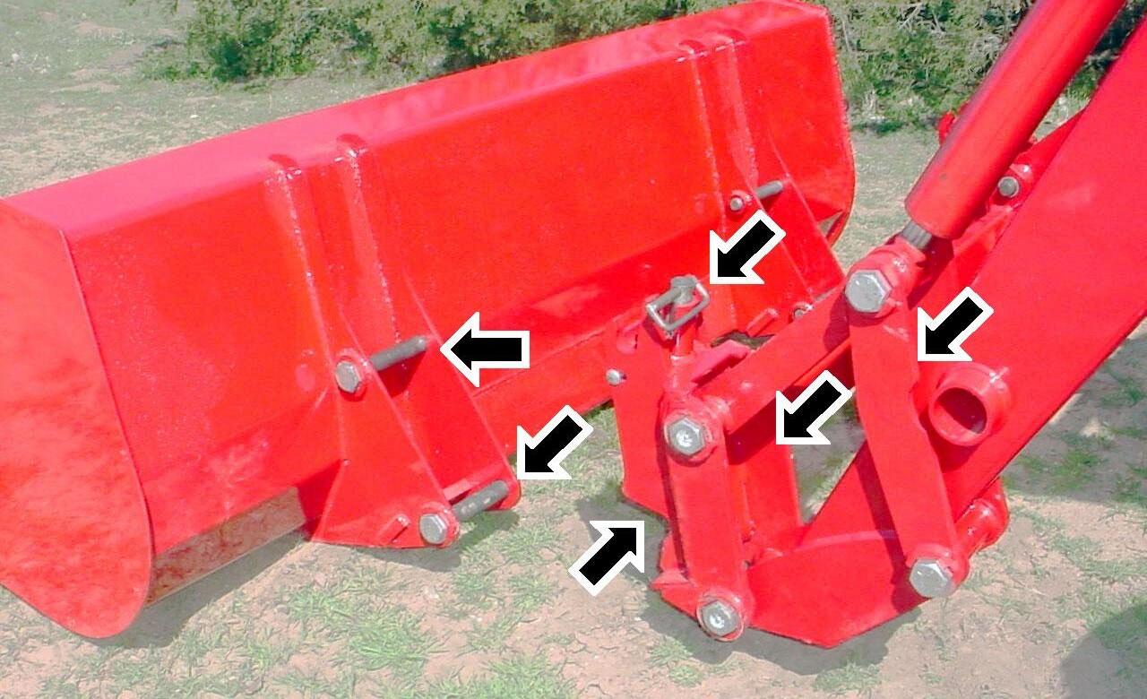
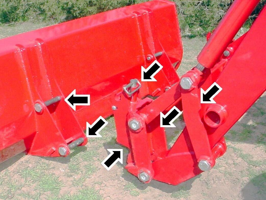
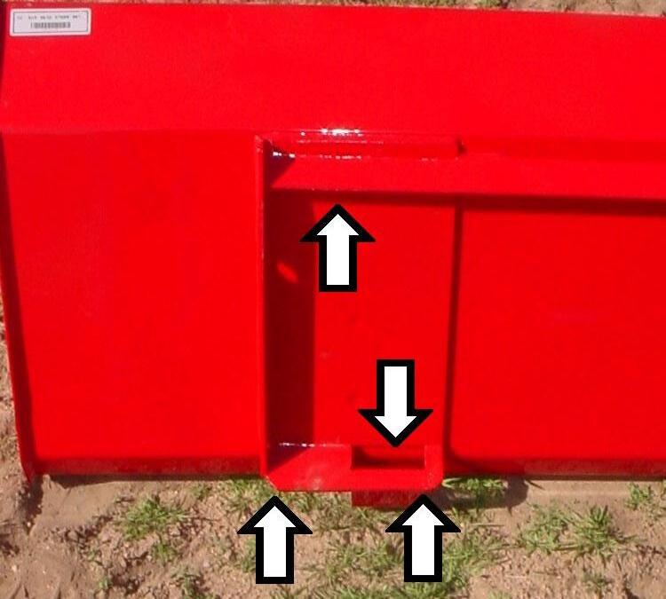
14.2.1. Make sure the following areas of Pin On Quick Attach are clean (SEE WHITE ARROWS).
♦ Pin On Bale Spear
♦ Pin On Pallet Fork
14.2.2. Install pin on quick attach direct to loader. Secure using pins and e-clips.
Top Pin 1-1/8" x 7.01" and E-Clip, 1 place each side.
Bottom Pin 1-1/8" x 7.01" and E-Clip, 1 place each side.
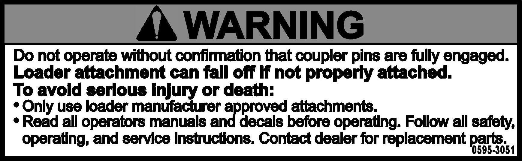
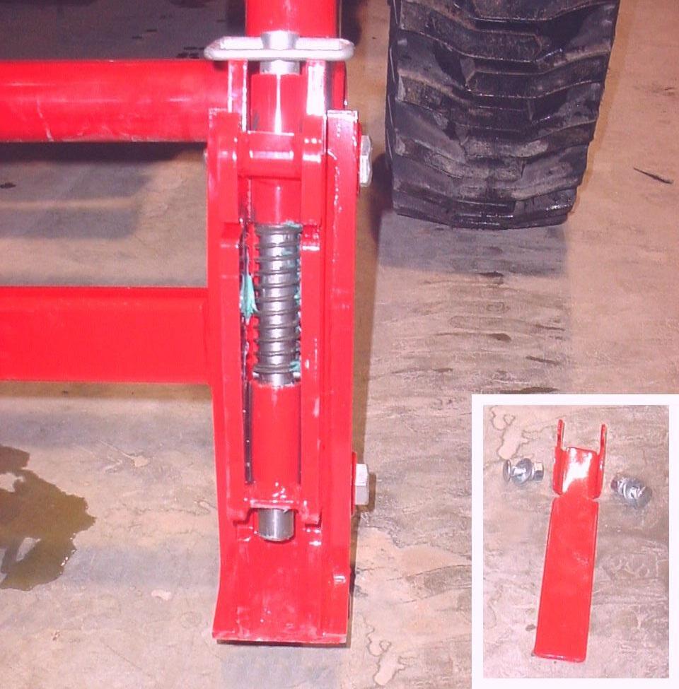
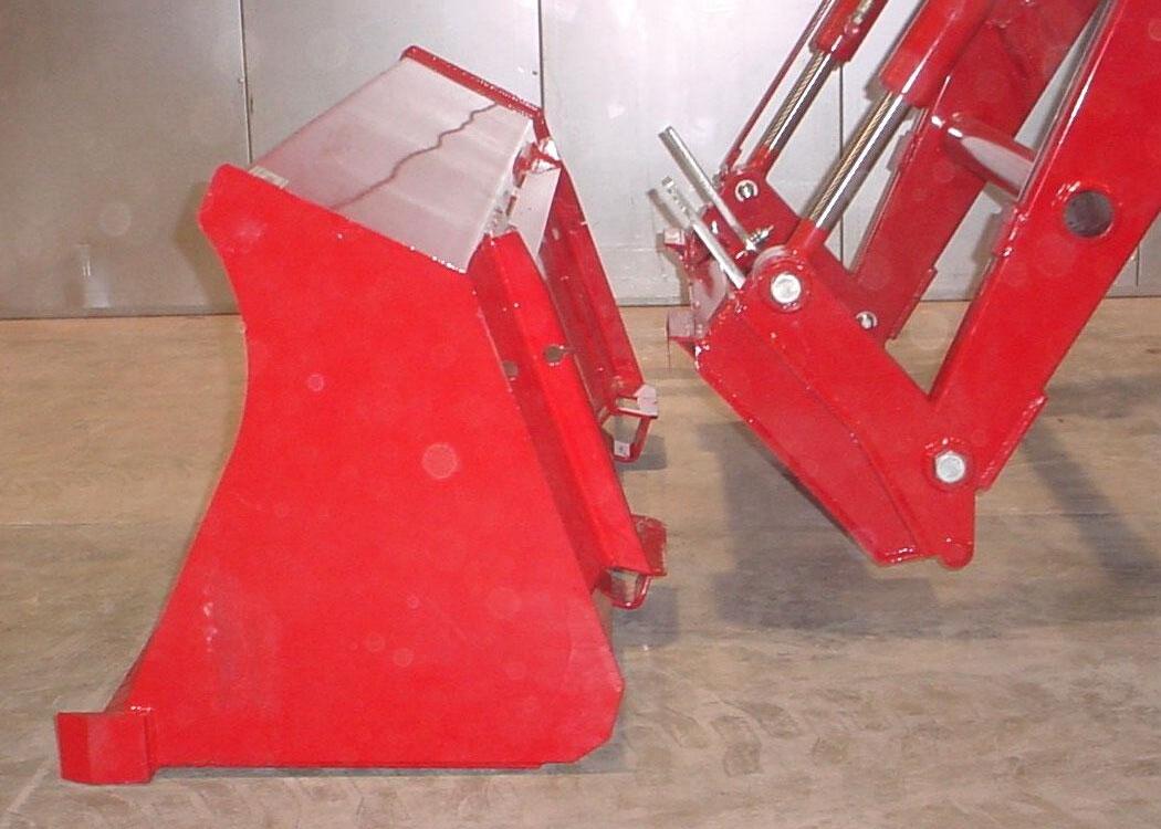
14.2.3. To attach bucket or attachment to loader, lower loader boom to ground with pin on quick attach rolled forward slightly. Pull up on pin handle until spring pin is above top bushing surface. Rotate pin assembly slightly. Flip handle forward. Repeat for other side.
Pin Assembly – pull up and rotate. Spring Pin – resting on top edge of bushing. Handle – flipped forward.
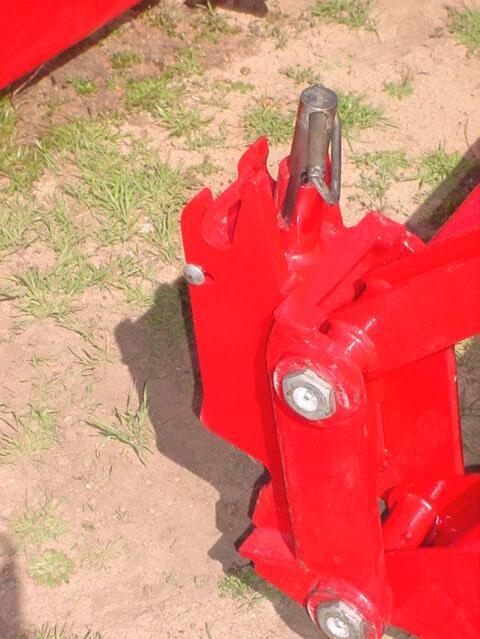
14.2.4. Roll quick attach forward by extending tilt cylinders just enough to allow pin on quick attach receiver to engage bucket or attachment upper pin. Drive tractor forward, aligning quick attach with bucket or attachment.
Bucket or Attachment Upper Pin
Quick Attach Receiver – align with bucket or attachment upper pin. Quick Attach - roll forward and lower.
NOTE: Over extension of tilt cylinders during this operation could cause damage to Pin On Quick Attach handles due to handles contacting bucket or attachment. Make sure handles are flipped forward.
14.2.5. When pin on quick attach is aligned with pin on bucket or attachment, raise loader boom slowly making sure pin on quick attach receivers engage attachment. Then roll quick attach back slowly.
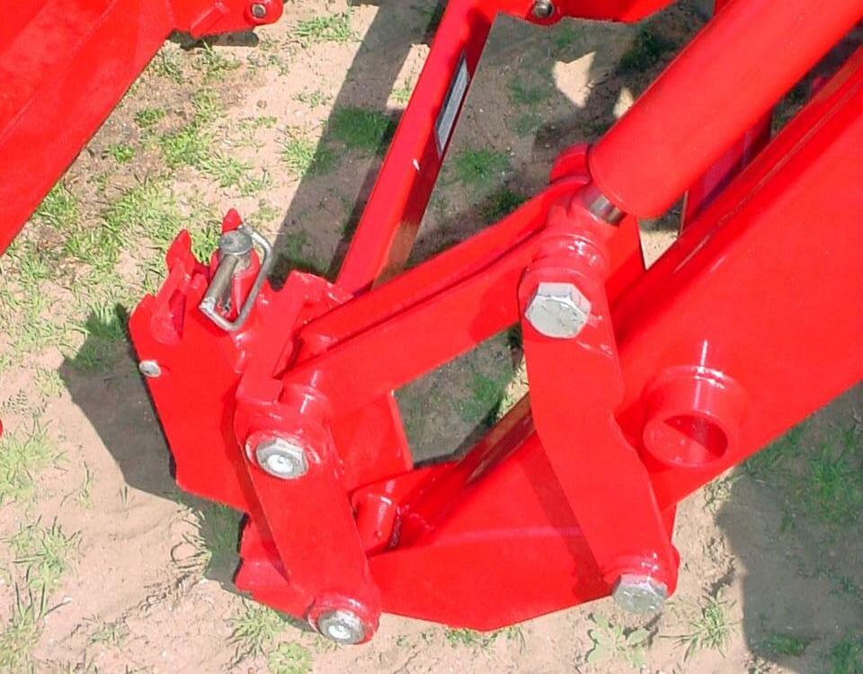
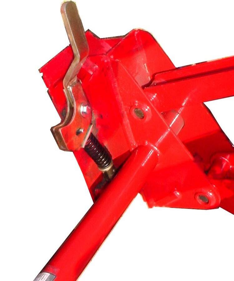
14.2.6. Position loader so attachment is approximately 1" off ground. Position pin assembly into the engaged position by pulling up on handle and rotating pin assembly so the spring pin is located in bushing slot. Repeat for other side.
Pin Assembly – rotate pin assembly so that spring pin is fully engaged in bushing slot.
Attachment – approximately 1" off of ground.
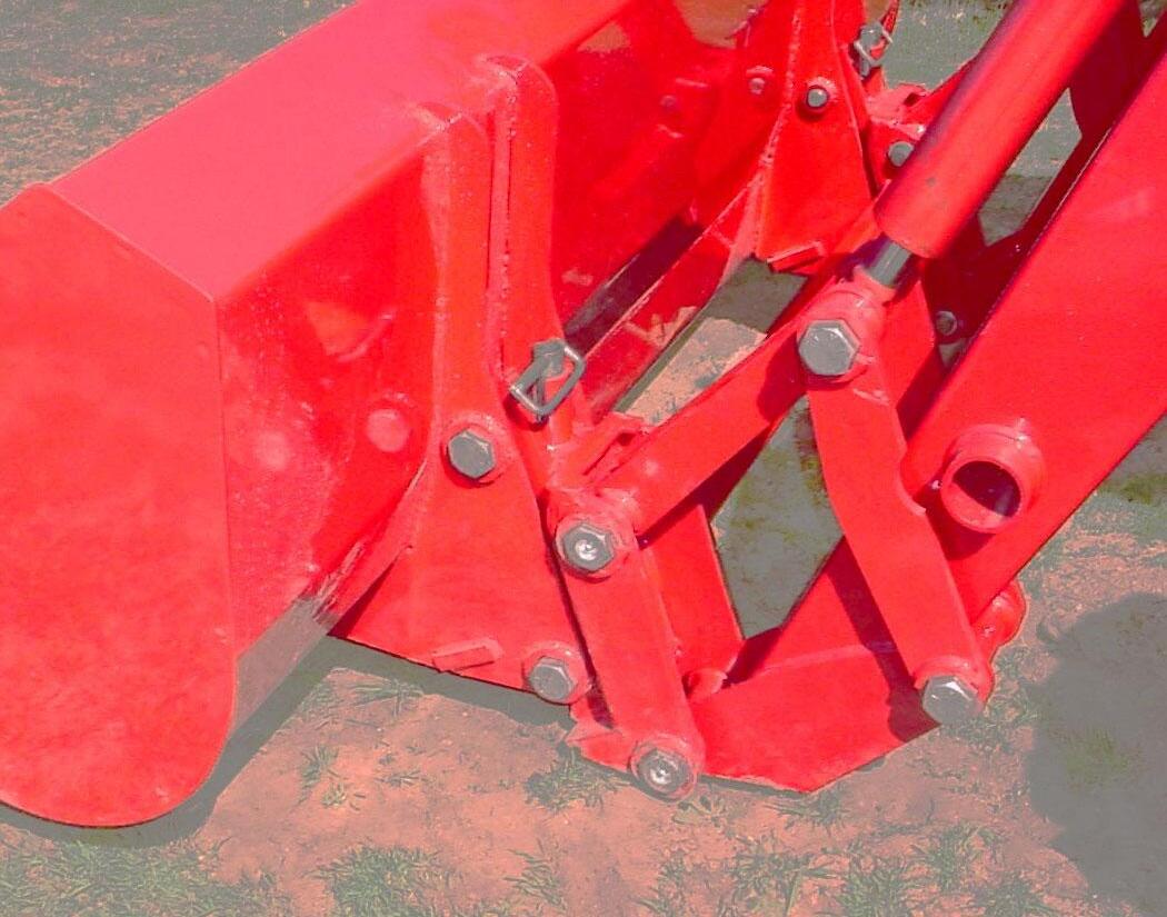
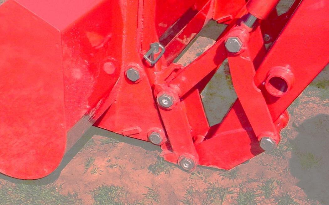
14.2.7. Check that bucket or attachment is securely attached to pin on quick attach by raising loader boom 3 to 4 feet, dumping bucket or attachment against stops, and checking to be sure bottom of bucket or attachment does not roll forward away from pin on quick attach.
WARNING: A bucket or attachment that is not securely locked into Pin On Quick Attach could come off during loader operation causing serious injury or death.
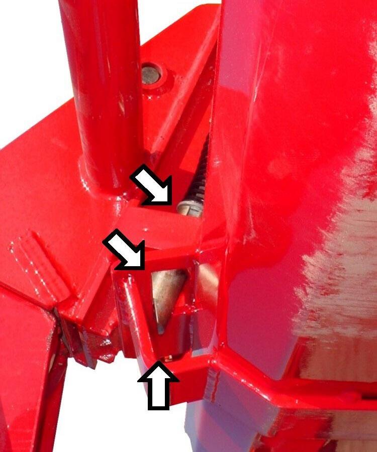
14.2.8. Inspect Pin On Quick Attach attaching areas to verify that Pin On Quick Attach pins have engaged bucket or attachment fully.
Spring Pin – fully engaged in bushing slot.
Bucket or Attachment Lower Pin.
Pin On Quick Attach Pin Assembly engaging bucket or attachment.
15. REMOVING BUCKET OR ATTACHMENT FROM PIN ON QUICK ATTACH
CAUTION: Before leaving the tractor seat, stop the engine and lock brakes when installing or removing bucket or attachment.
CAUTION: Do not stand, walk, or work under a raised loader or attachment unless it is securely blocked or held in position. Accidental movement of valve handle/handles or leaks in the hydraulic system could cause the loader to drop, or attachment to dump, causing severe injury.
15.1. OPERATING INSTRUCTIONS
15.1.1. To disconnect bucket or attachment from loader, position bucket or attachment slightly rolled back and approximately 1" off of ground. Pull up on pin handle until spring pin is above top bushing surface. Rotate pin assembly slightly. Flip handle forward. Repeat for other side.
Bucket or Attachment – rolled slightly back.
Pin Assembly – pull up and rotate. Spring Pin – resting on top edge of bushing. Handle – Flip Forward.
15.1.2. Roll bucket or attachment forward and lower to ground. Back loader away from bucket or attachment.
NOTE: Over extension of tilt cylinders during this operation could cause damage to Pin On Quick Attach handle due to handle contacting bucket or attachment.
15.1.3. Position pin assembly into the engaged position by pulling up on handle and rotating pin assembly so the spring pin is located in bushing slot. Repeat for other side.
Pin Assembly – Rotate pin assembly so that spring pin is fully engaged in bushing slot.
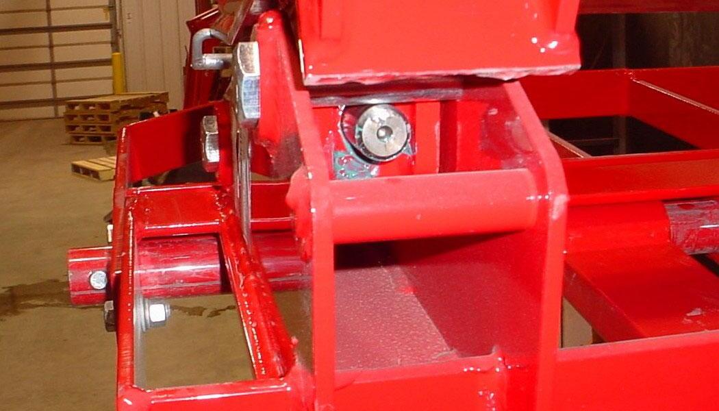
16. SERVICE AND LUBRICATION FOR PIN ON QUICK ATTACH
16.1.
Keep These Areas Clean
16.1.1. Keep these areas clean to allow pin on quick attach system to function properly.
IMPORTANT: To maintain your Pin On Quick Attach System functioning properly, always inspect Pin On Quick Attach System components for damage or wear. If damage or wear exists, replace components immediately.
16.2. LUBRICATE ANNUALLY
16.2.1. Lubricate Quick Attach Pins annually using a good grade of grease. Remove front covers of quick attach by loosing 3/8" nut and then removing sealant and cover plate. Grease components and pin and then reinstall cover plate and seal using Sika-Flex Sealant.
Lubricate these areas of Pin On Quick Attach.
Cover Plate shown removed.
Lubricate these areas of Pin On Quick Attach.
17. OPTIONAL SKID STEER TOOL CARRIER SYSTEM
IMPORTANT: Read safety information in this section and on decal before operating attachment.
NOTE: Skid Steer Tool Carrier System is optional equipment
WARNING: Always read and follow operating instructions before operating Skid Steer Tool Carrier System.
17.1. RECOMMENDED LOADER FACTORY APPROVED ATTACHMENTS
17.1.1. Use only Loader Factory Approved Attachments for mounting on this Skid Steer Tool Carrier System.
17.2. NON-LOADER FACTORY ATTACHMENTS
17.2.1. If you are going to connect a non-Loader Factory Attachment to this Skid Steer Tool Carrier System, read and understand the following instructions and safety information. Always make sure Skid Steer Tool Carrier is locked onto all attachments.
NOTE "A": If your attachment back is not running at a 20 degree angle, your loader rollback and dump angles will change per attachment angle change.
NOTE "B": If your attachment point is lower than this, your attachment may not touch the ground when loader is fully lowered.
17.3. SKID STEER TOOL CARRIER SYSTEM SERVICE & LUBRICATION
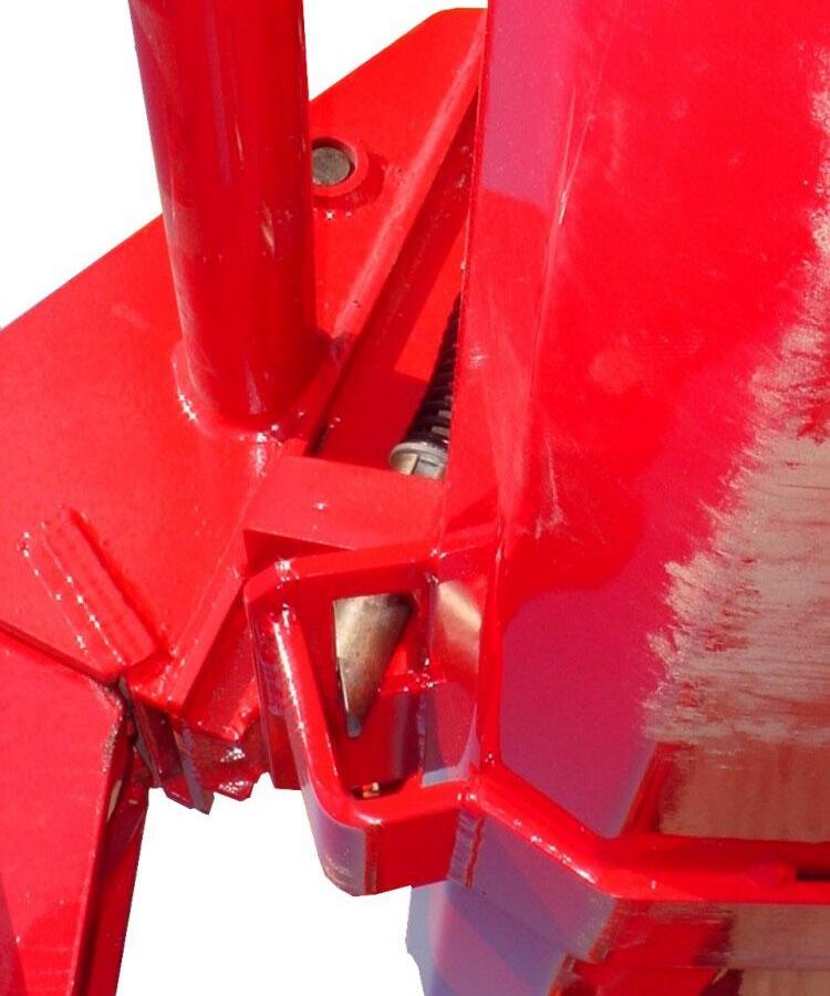
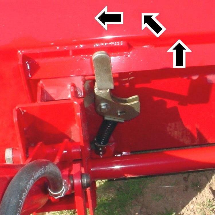
IMPORTANT: To maintain your Skid Steer Tool Carrier System functioning properly, always keep handle components and latching areas clean. Keep all these areas clean. Refer to 3 photos at right and below.
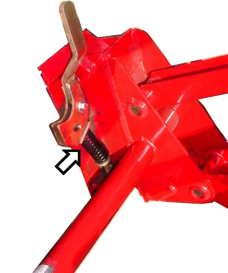
IMPORTANT: To maintain your Skid Steer Quick Attach System functioning properly, always inspect Skid Steer Quick Attach System components for damage or wear. If damage or wear exists, replace components immediately.
17.3.1. Check and tighten this 1/2" bolt after every 20 hours of operation.
17.3.2. A small amount of light oil applied to pins occasionally will improve ease of function of skid steer latching components.
17.3.3. Inspect latching components and groove pins. If damaged, only replace with Factory approved components.
18. INSTALLATION & OPERATION OF SKID STEER TOOL CARRIER SYSTEM
IMPORTANT: Read safety information in this section and on decal before operating attachment.
WARNING: Always read and follow operating instructions before operating Skid Steer Tool Carrier System.
18.1. INSTALLATION INSTRUCTIONS
IMPORTANT: Do not extend bucket cylinders without Skid Steer Tool Carrier installed on loader. Failure to follow these instructions could cause loader damage and void warranty.
18.1.1. Install Skid Steer Tool Carrier to loader. Secure as shown.
Top Pin 1-1/8" x 7.01" and E-Clip, 1 place each side.
Bottom Pin 1-1/8" x 7.01" and E-Clip, 1 place each side.
18.2. SKID STEER TOOL CARRIER HANDLES IN DISENGAGED POSITION
18.2.1. To position handles into the handle disengaged position, pull skid steer tool carrier handle upward.
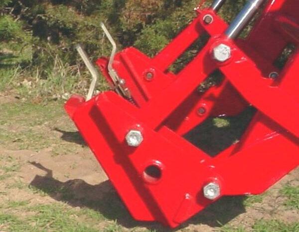
Pull Handles Upward
(1) Handles disengaged position.