7 minute read
3.3. HYDRAULIC INSTALLATION


3.3.1. Remove RH cab console components to reveal existing console bracket. Save console components and console hardware.
RH Cab Wall
Existing Console Bracket (installed on tractor).
3.3.2. Remove RH cab floor plate cover to reveal opening to outside of cab. Save floor hardware. Cab Floor Opening.
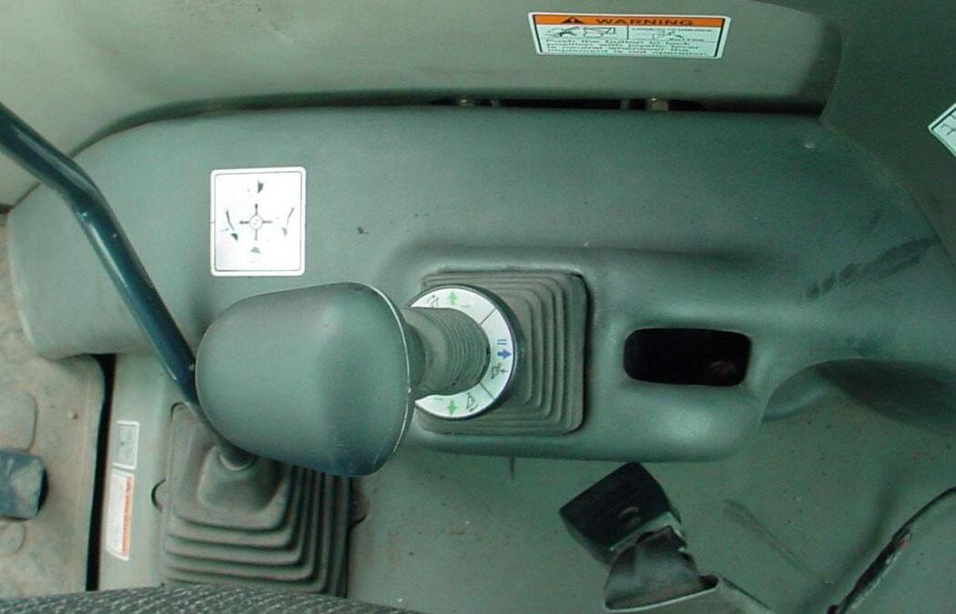
3.3.3. Peel rubber boot back from controller to expose controller linkage. Position single lever controller with cables so solid post is positioned toward front and center of tractor.
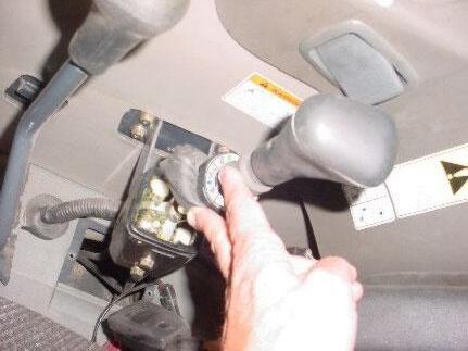
Float part of decal faces toward front of tractor. Rubber Boot, in raised position. Lift Cable controls Raise & Lift functions of Loader.
Solid post positioned toward front and center of tractor.
Single Lever Controller.
8mm x 80mm Hex Bolt Grade 10.9 and 5/16" Lockwasher, 2 places.
Tilt Cable controls Dump & Rollback functions of Attachment.
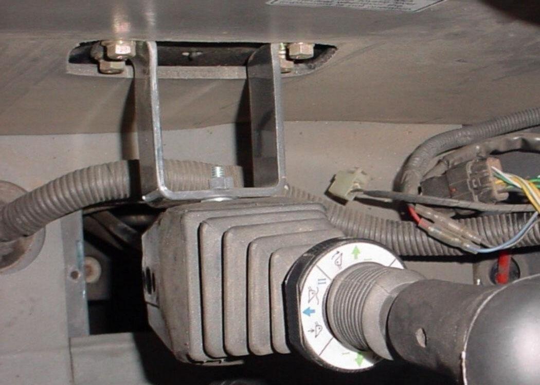
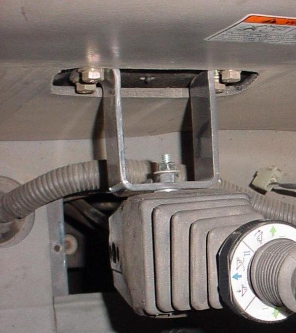
3.3.4. Install single lever controller to existing console bracket using 8mm x 80mm hex bolts Grade 10.9 and 5/16" Lockwashers.
Existing Console Bracket
Two 5/16" spacer flatwashers on top bolt only.
Single Level Controller with pre-assembled Cables.
IMPORTANT NOTE: Two flatwashers must be used on top bolt between controller and console bracket to tilt handle toward operator. Do not use flatwashers on bottom bolt.
Two 5/16" spacer flatwashers on top bolt only. No Flatwashers on bottom bolt.
Existing Console Bracket
Single Level Controller
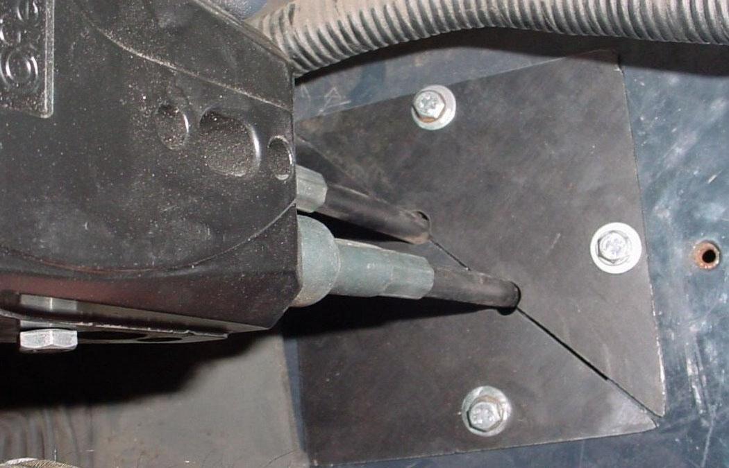
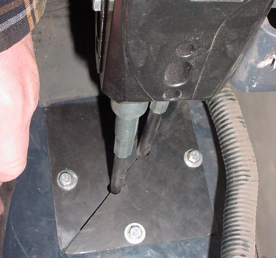
3.3.5. Route cables down through cab floor opening. Install new triangle floorboard plates around cables re-using floor hardware just removed.
Triangle Floorboard Plates. Re-use floor hardware.
3.3.6. Apply silicone sealant around cables and between triangle plates to reduce air and dust leaks. Silicone sealant must be supplied by installer.
3.3.7. Reposition rubber boot over single level controller.
Rubber Boot repositioned.
3.3.8. Reinstall cab console components and secure using console hardware.
Cab Console Components Reinstalled
3.3.9. Remove RH cab step. Save step and step hardware.
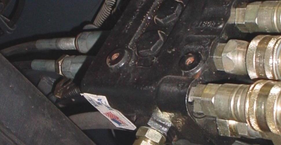
3.3.10. From RH side of tractor underneath cab, remove hydraulic hose connecting tractor pressure port to tractor power beyond port. Keep tractor fittings in place.
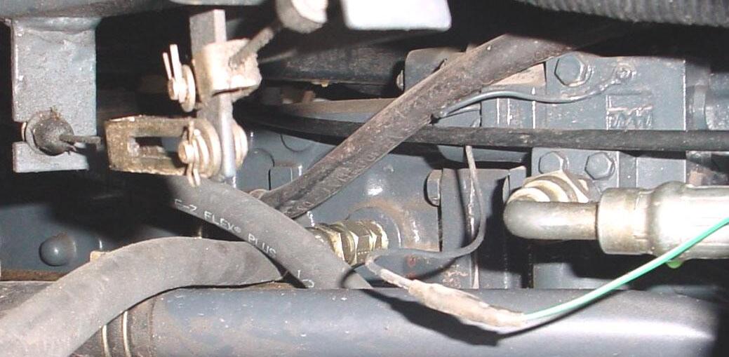
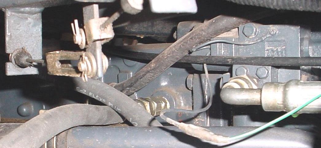
Tractor Power Beyond Port Location.
Tractor Hose – Remove.
Tractor Fittings – Do Not Remove.
Tractor Pressure Port Location.
Tractor Plug – Remove.
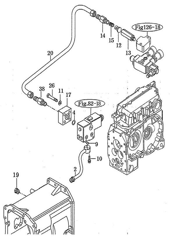
Tractor Transmission Port
Tractor Pressure Port
Tractor Straight Fitting
Hose 1/2" x 17"
BSPP F 1/2" 90o x JICF 3/4"
Tractor Return Port
Fitting Straight
BSPT F 1/2" x JIC M 7/8"
Hose 1/2" x 25"
JICF 7/8" X JICF 3/4" 90o
Tractor Power Beyond Port
Tractor Straight Fitting
Hose 1/2" x 60"
BSPT M 1/2" 90o x JICF 3/4"
NOTE: Do not start tractor engine until these hoses are installed and secured to the loader valve.
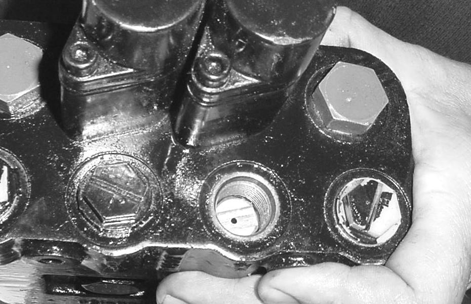
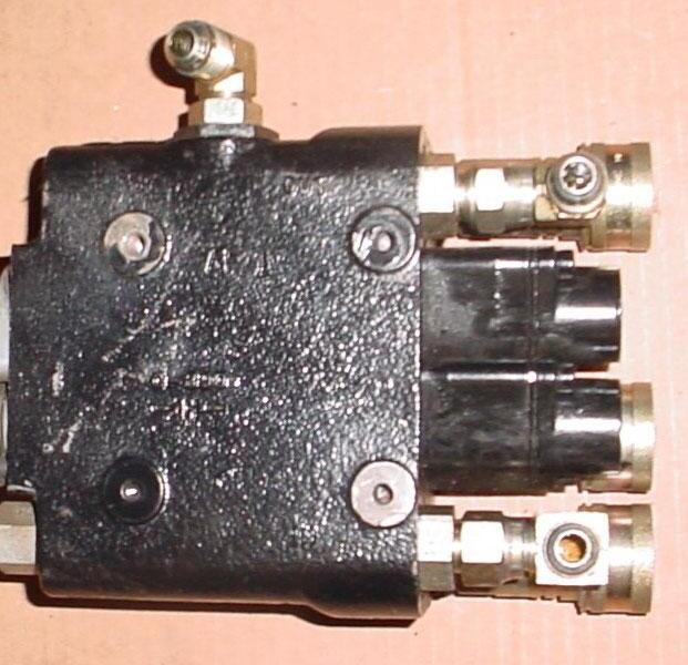
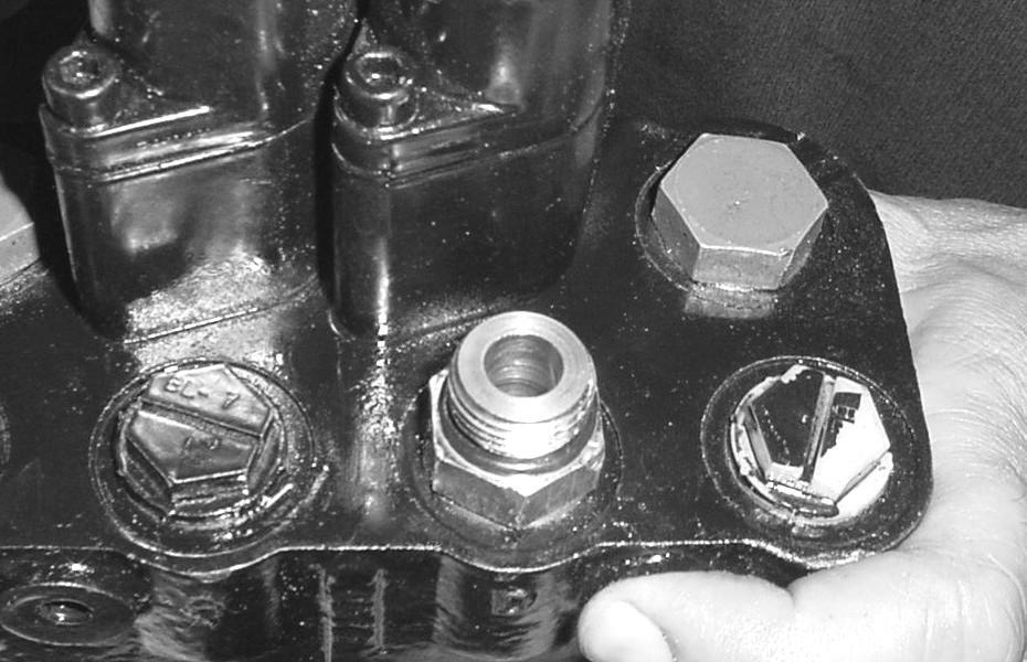
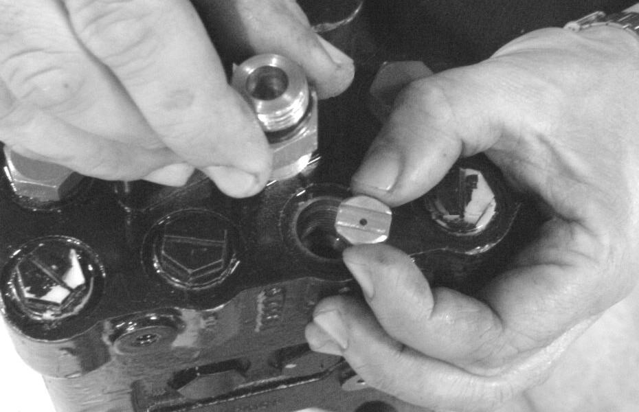
3.3.15. Loaders That Are Not Equipped With Hydraulic Self Leveling: Rotate loader valve so that Port "D" is upward. Install orifice fitting by dropping it into Port "D" with slot of orifice facing upward. Screw fitting into Port "D" to secure orifice into port. (Do not install orifice on Loaders equipped with Hydraulic Self Leveling.)
Port "D" in Loader Valve. Orifice (slot upward). Fitting Straight ORBM 3/4" x ORBM 3/4".
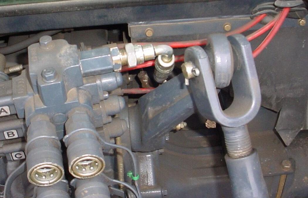
3.3.16. Install fittings to valve as follows:
Power Beyond side of valve.
Port "C" Tilt Cylinder Base End
Yellow Tie
Port "D" Tilt Cylinder Rod End
Red Tie
Port "B" Lift Cylinder Rod End
Blue Tie
Port "A" Lift Cylinder Base End
Green Tie
NOTE: Do not tighten power beyond or pressure hose until they are connected to tractor.
(1) Port "A", "B", "C", & "D": Install Fitting Straight ORBM 3/4" x ORBM 3/4".
(2) Port "D": Install Male Quick Coupler, only into Port "D".
(3) Port "A", "B", & "C": Install Female Quick Coupler, into remaining three ports.
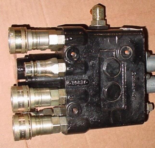
(4) Power Beyond Port: Install Fitting 90o JICM 3/4" x ORBM 3/4".
(6) Return "OUT" Port: Install Fitting Straight JICM 3/4" x ORBM 7/8".
(7) Pressure "OUT" Port: Install Fitting 90o JICM 3/4" x JICF 3/4".
(8) Pressure "IN" Port: Install Fitting Straight JICM 3/4" x ORBM 7/8".
(9) Pressure "IN" Port: Install Fitting 90o JICM 3/4" x JICF 3/4".
No Relief Plug installed at Factory
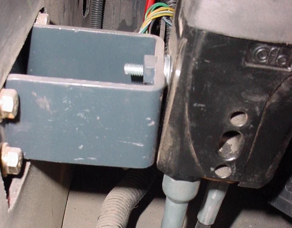
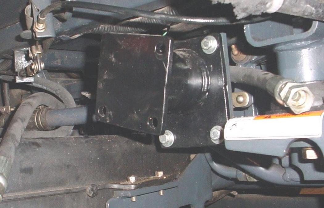
3.3.17. Install valve mount to tractor mount located under RH side of cab behind cab step that was just removed. Secure using 8mm x 20mm hex bolt and 5/16" lockwasher, 3 places.
Valve Mount 8mm x 1.25P x 20mm Hex Bolt and 5/16" Lockwasher, 3 places.
Tractor Mount
3.3.18. Install valve to valve mount under RH side of cab using 5/16" x 1" hex bolt and 5/16" lockwasher, 3 places.
Valve 5/16" x 1" Hex Bolt and 5/16" Lockwasher, 3 places.
Valve Mount
3.3.19. Identify and trace cables from Single Lever Controller.
Raise and Lower (Lift) Cable is Frontward Cable
Dump and Rollback (Tilt) Cable is Rearward Cable
3.3.20. Install raise and lower (lift) cable to upper spool of valve and dump and rollback (tilt) cable to lower spool of valve as follows. Refer to photo and illustration following.
A. Thread large jam nuts entire length of threaded hubs and onto cables.
B. Place dual flange over both cables.
C. Thread sleeves entire length of threaded hubs and onto cables.
D. Thread small jam nuts onto cable threaded rods until they bottom out on threads.
E. Place connectors onto threaded rods and against jam nuts. Align connectors so they will mate with spool terminal eyes and secure jam nuts against connectors.
F. Slide connectors onto spools and align the holes. Insert pins through connectors and spool holes.
G. With cables attached to valve and single handle controller, turn the sleeves onto threaded hubs until they are flush with the valve face.
NOTE: When turning the sleeves, make sure the single handle controller remains in the neutral position.
H. Tighten large nuts against sleeves to lock in position.
I. Slide dual flange into position and secure using socket head cap screws and flatwashers.
NOTE: Over-tightening will distort flange.
NOTE: Controller handle can be repositioned slightly by tightening or loosing sleeves.
Install
Dump and Rollback Raise and Lower (Tilt) Cable to (Lift) Cable to Lower Spool of Valve Upper Spool of Valve
Cable Adapter Group Valve
3.3.21. Route 17" pressure hose to fittings in pressure port of valve.
17" Pressure Hose
3.3.22. Route 25" return hose to fittings in return port of valve.
25" Return Hose
3.3.23. Route 60" power beyond hose to fitting in power beyond port of valve.
60" Power Beyond Hose
3.3.24. Remove all twists from hoses then tighten hydraulic connections.
3.3.25. Check that all hydraulic connections have been tightened.
3.3.26. Reinstall RH cab step reusing cab step hardware.
Cab Step Hardware
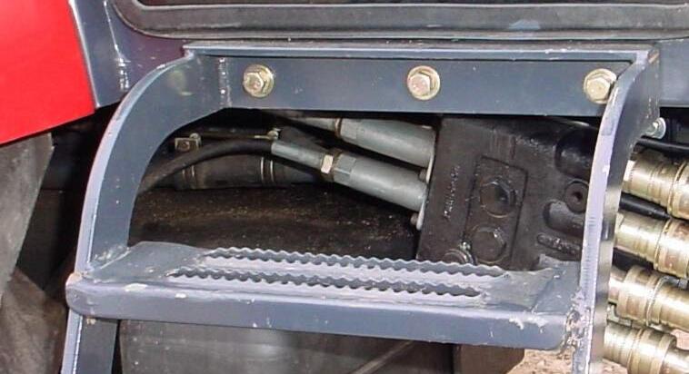

Raise and Lower (Lift) Cable Dump and Rollback (Tilt) Cable RH Cab Step
Single Lever Controller
Solid Post – located front and center of Tractor
Triangle Floorboard Plates
Raise and Lower (Lift) Cable Frontward
Dump and Rollback (Tilt) Cable Backward
Pressure "IN" Line 17" hose (opposite of power beyond port)
Return "OUT" Line 25" hose
Return "OUT" Line Fitting
Power Beyond Line 60" hose
3.4. LOADER INSTALLATION
3.4.1. Remove all loader components from shipping package.
CAUTION: Lift and support all loader components safely.
IMPORTANT: Do not extend tilt cylinders without attachment pinned to loader. Failure to follow these instructions could cause loader damage and void warranty.
3.4.2. Loader valve hoses and quick couplers have been pre-assembled on loader. Unwrap these hoses by cutting nylon ties securing them to side of loader.
3.4.3. Before installing loader to tractor, use a hoist to install pin on bucket or pin on attachment and bucket or skid steer attachment and bucket on loader. Secure using pins and e-clips, 4 places.
Top Pin 1-1/8" x 7.01", Grease Fitting 1/4"-28 and E-Clip, 1 place each side.
Bottom Pin 1-1/8" x 7.01", Grease Fitting 1/4"-28 and E-Clip, 1 place each side.
Refer to Section 10 for Pin On Bucket, page 49.
Refer to Section 11 for Pin On Bale Spear, pages 50 to 51.
Refer to Section 12 for Pin On Pallet Fork, pages 52 to 53.
Refer to Sections 13 to 16 for Optional Pin On Quick Attach System, pages 54 to 59.
Refer to Sections 17 to 20 for Optional Skid Steer Tool Carrier System, pages 60 to 67.
3.4.4. Following these instructions will add stability to loader package and will allow easier handling of loader with hoist.
3.4.5. Support the loader by using a hoist. Install loader to mounting brackets previously installed on tractor. Refer to Section 8 — Mounting the Loader, pages 45 to 47.
CAUTION: Lift and support all loader components safely.
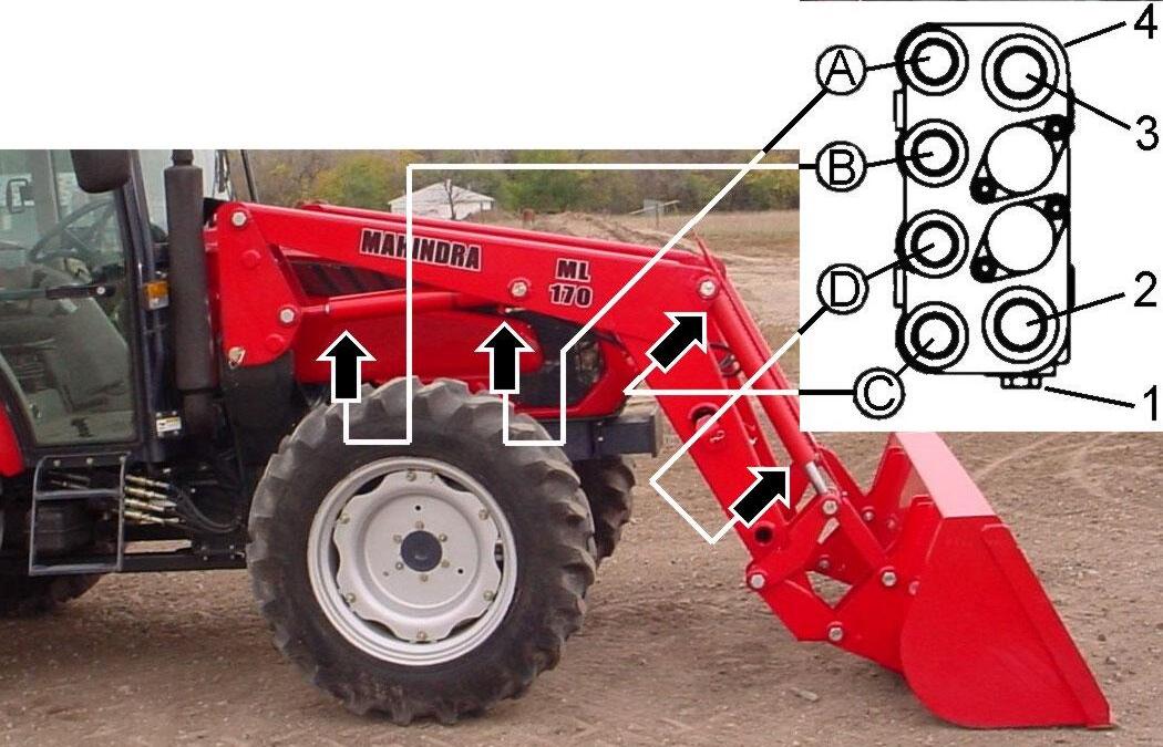
3.5. CONNECT HYDRAULICS
3.5.1. Verify all working port hose connections.
(C) Connect Port "C" to Tilt Cylinder Base End
(D) Connect Port "D" to Tilt Cylinder Rod End
(B) Connect Port "B" to Lift Cylinder Rod End
(A) Connect Port "A" to Lift Cylinder Base End
(1) "PBY" Power Beyond Port.
(2) "OUT" Return Port.
(3) "IN" Pressure Port.
(4) Loader Valve.
3.5.2. Using color nylon ties, install one on each quick coupler fitting. These color ties will allow easy identification of loader circuits when mounting and dismounting loader.
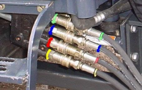
Port "A" – Green Tie
Lift Cylinder Base End
Port "B" – Blue Tie
Lift Cylinder Rod End
Port "D" – Red Tie
Tilt Cylinder Rod End
Port "C" – Yellow Tie
Tilt Cylinder Base End
Port "A" – Green Tie
Lift Cylinder Base End
Port "B" – Blue Tie
Lift Cylinder Rod End
Port "D" – Red Tie
Tilt Cylinder Rod End
Port "C" – Yellow Tie
Tilt Cylinder Base End
IMPORTANT: Valve Port "C" must be connected to Tilt Cylinder Base End port and Valve Port "D" must be connected to Tilt Cylinder Rod End port or else Regen Function of Valve will not work correctly.
CAUTION: When properly installed, the external valve handle will control loader hydraulic circuits as described in Item 4.4, page 32.
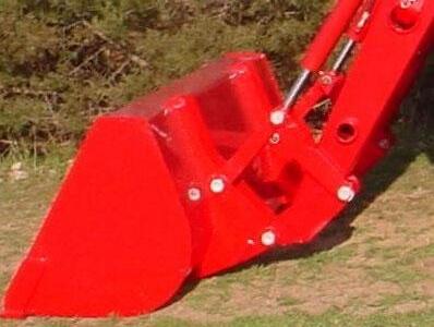
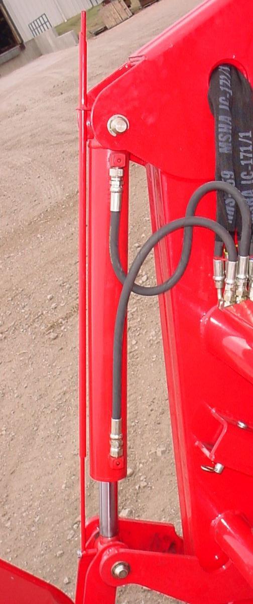
3.6. BUCKET LEVEL INDICATOR
3.6.1. Install bucket level indicator rod assembly into bucket level indicator tube assembly.
3.6.2. Attach bucket level indicator tube assembly to base end of RH tilt cylinder using 5/16 x 1-1/2" hardware.
3.6.3. Attach bucket level indicator rod assembly to rod end RH tilt cylinder using 5/16" x 1/2" hardware.
3.6.4. Adjust bucket level tube for proper alignment with bucket level rod by sliding slotted bracket to desired position and tightening bolt.
3.6.5. After installing loader on tractor, position loader on ground with bucket flat, then paint or mark end of bucket level indicator rod so operator can identify when bucket is level on ground.

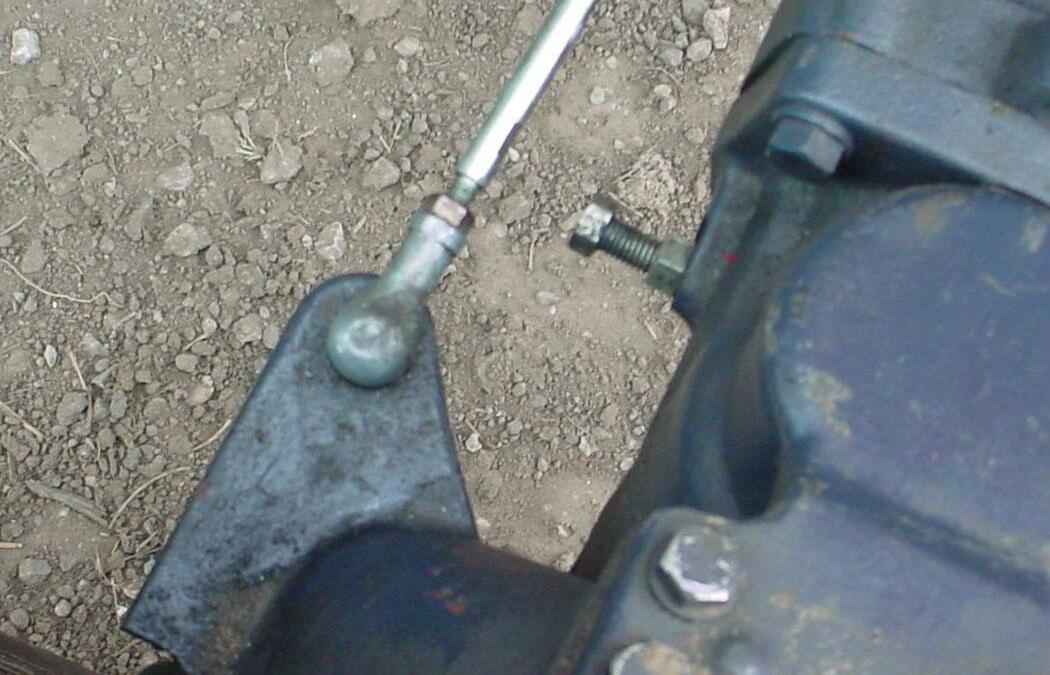
3.7. STEERING STOP
3.7.1. Set steering stop out to a maximum of 29/32" between top of nut and top of bolt head.
Hex Bolt 5/16" x 1-1/2" Grade 5, 5/16" Lockwasher, and 5/16" Flatwasher
Bucket Level Indicator Tube Assembly
Bucket Level Indicator Rod Assembly
Hex Bolt 5/16" x 1/2" Grade 5 and 5/16" Lockwasher
Paint or mark end of BLI rod.