19 minute read
OVER4TIMESOFHEIGHT


HEIGHT
3. Lock the both brake pedals together.
[BRAKE LOCKED]
BRAKE PEDAL LOCK
BRAKE PEDAL (LEFT)
BRAKE PEDAL (RIGHT)
4. Make sure that differential lock is unlocked.
GEAR DRIVE TRANSMISSION (Shuttle Type Only)
The gear drive transmission has a forward and a reverse gear section and a four-speed main shift gear section, and a two-speed range section. This arrangement gives eight forward and eight reverse speeds.
Transmission Operation
1. Push the clutch pedal and stop the tractor. Move the gear shift lever to the gear needed.
2. Move the range shift lever to the position needed, H, L (The tractor must be stopped before the range lever is operated.)
3. Move the shuttle lever to Forward or Reverse position.
4. Release the clutch pedal slowly.
[Range shift lever, Gear shift lever]
RANGE SHIFT LEVER
GEAR SHIFT LEVER
Operating Instructions
[Shuttle lever]
NOTE: When shifting from fourth range to another range, be careful not to run the engine at more than 2000 RPM.
IMPORTANT: Before selecting a new range, push the clutch pedal and stop the tractor. Do not change range when the tractor is moving.
HYDROSTATIC DRIVE TRANSMISSION (HST Type Only)
The Hydrostatic drive transmission has a forward/reverse hydrostatic section and a twospeed range section. This arrangement gives two forward and two reverse speeds ranges.
Transmission Operation
1. Push the clutch pedal fully and stop the tractor. Move the range shift lever to the position needed, H or L.
2. Release the clutch pedal slowly.
3. Operate the speed ratio control pedal to move the tractor.
To shift from reverse to forward or from forward to reverse, reduce the speed and switch to depress the speed ratio control pedal one from the other.
IMPORTANT: Before selecting a new range, stop the tractor and push the clutch pedal. Do not change range when the tractor is moving.
Warning
Do not change the running direction near ditches, embankments and holes.
If you operate inappropriately, the tractor could move in unexpected direction, causing an accident.
Select an appropriate speed to control the tractor completely and stably. Reduce speed when turning, crossing slopes, and running on rough, slick or muddy surfaces. Otherwise, it could cause an accident.
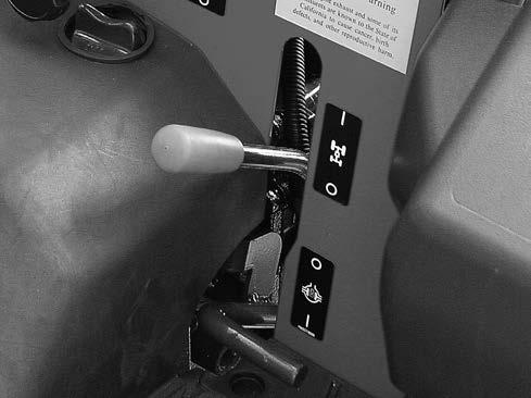
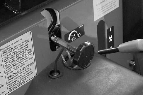
HYDROSTATIC SPEED LOCK LEVER (HST Type Only)
The speed ratio control pedal of hydrostatic drive has a speed lock lever. This lever is used to keep a constant forward speed without controlling the pedal. It can not be used for reverse speed. The lever is located under the instrument panel. Operate the speed lock lever as follows:
1. Determine forward speed as you need by pressing the speed ratio control pedal forward.
2. Move the lock lever upward to lock the position of the pedal. (It can keep the forward speed constant).
3. Remove your foot from the pedal.
4. To release the lock, move the lock lever downward.
5. Increase of forward speed, speed ratio can be obtained to max. speed by pressing the pedal forward while the lock lever is in lock position. However, decrease of forward speed ratio or change to reverse speed can not be obtained, while the lock lever is in lock position.
6. To decrease forward speed ratio or change to reverse speed, put your foot on the pedal first, then release the lock lever. Control speed ratio or direction with the foot pedal.
NOTE:
1. The lock lever can not be released by pressing the brake pedal.
2. The lock lever can not be released by pressing the hydrostatic speed ratio control pedal.
3. Make sure to keep the lock lever in the off position when starting the tractor.
4. Return the lock lever to the off position when stopping the tractor.
NOTE: The speed ratio control pedal will return to neutral position and the tractor will stop If your foot is not on the pedal.
Operating Instructions
MECHANICAL FRONT DRIVE (4WD)
To disengage the 4WD, push the clutch pedal, stop the tractor and move the 4WD control lever down to the OFF position.
IF THE 4WD IS DIFFICULT TO DISENGAGE, DO THE FOLLOWING:
1. Move the range shift lever to L range.
2. Slowly release and press the clutch pedal to move the tractor forward or rearward small amount.
Use the 4WD to obtain improved traction in loose, sandy or wet soil conditions. 4WD will also give improved steering control and will reduce soil compaction. 4WD can be engaged or disengaged as needed by the 4WD control lever located on the LH side below the operators seat.
To engage the 4WD, press the clutch pedal down, stop the tractor and move the 4WD control lever up to the ON position.
IF THE 4WD IS DIFFICULT TO ENGAGE, DO THE FOLLOWING:
1. Push the clutch pedal.
2. Move the range shift lever to L range.
3. Release the clutch pedal slowly, move the tractor forward or rearward small amount.
4. Move the 4WD control lever up until fully engaged with proper force.
3. Push the clutch pedal and stop the tractor.
4. Move the 4WD control lever down until completely disengaged.
Warning
Do not go up a steep slope in the forward direction even though 4WD is more powerful than 2WD. Otherwise, the tractor will roll backward, causing an accident.
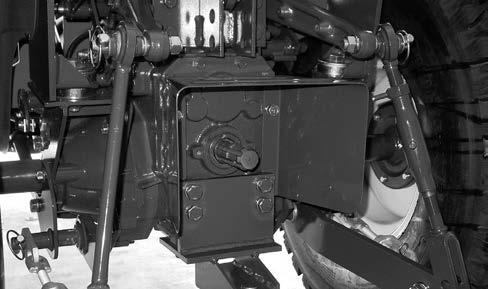
Differential Lock
[Shuttle Type]
RIGHT SIDE of the transmission
[HST Type]
Operating Instructions
IMPORTANT: Do not engage the differential lock while one rear wheel is rotating and the other rear wheel is stopped. Always stop the wheel that is rotating and then engage the differential lock.
IMPORTANT: When you engage or disengage the differential lock, the front wheels must be in the straight forward position. Before turning the tractor, disengage the differential lock.
TO DISENGAGE THE DIFFERENTIAL LOCK: The differential lock will disengage when the differential lock pedal is released. If the differential lock does not disengage easily, push down on either brake pedal instantaneously.
WARNING
Do not engage the differential lock when travelling on a road or operating at a high speed. Otherwise, the steering will be disabled, causing an accident.
LEFT SIDE of the transmission
Your tractor has a differential lock that will make both rear wheels turn at the same speed. The differential lock prevents loss of power when one wheel does not have traction but the other wheel does have traction. It also provides a straight in line steering aid when opening up the field and to control implement overlap.
TO ENGAGE THE DIFFERENTIAL LOCK: Depress and hold the differential lock pedal down.
POWER TAKE OFF (REAR PTO)
WARNING
Be sure to move the PTO control lever to the OFF position and stop the engine and allow all rotating components to come to a complete stop before working on or near the PTO shaft, or servicing, inspecting or cleaning the PTO driven implement. During PTO driven machinery working, stay clear of rotating parts and install required safe cover. Otherwise, it could cause serious injury or death due to entanglement, etc.
Rear PTO
The rear PTO is a 540 RPM with a 34.9 mm (1 3/8 inch) diameter 6 spline output shaft.
ENGAGE THE REAR PTO AS FOLLOWS:
1. Push the clutch pedal fully.
2. Move the PTO control lever to the ON position.
3. Release the clutch pedal slowly.
DISENGAGE THE REAR PTO AS FOLLOWS:
1. Push the clutch pedal fully.
2. Move the PTO control lever to the OFF (Engine Start) position.
3. Release the clutch pedal slowly.
NOTE: Keep the PTO control lever in the OFF (Engine Start) position when starting the engine and when the PTO is not being used.
The following table shows the required speed to get the required Rear PTO output shaft speed.
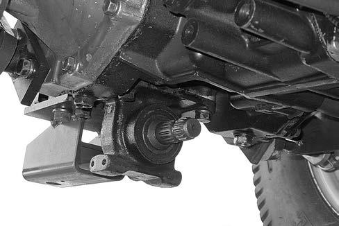
POWER TAKE OFF (MID PTO)
Mid PTO (IF EQUIPPED)
The Mid PTO has a 25.4 mm (1 inch) diameter 15 spline output shaft.
Operating Instructions
DISENGAGE THE MID PTO AS FOLLOWS:
1. Push the clutch pedal fully.
2. Move the Mid PTO control lever to the OFF (Engine Start) position.
3. Release the clutch pedal.
NOTE: Keep the Mid PTO control lever in the OFF (Engine Start) when starting the engine and when the PTO is not being used.
The following table shows the required engine speed to get the required Mid PTO output shaft speed.
MID
ENGAGE THE MID PTO AS FOLLOWS:
1. Push the clutch pedal fully.
2. Move the Mid PTO control lever to the ON position.
3. Release the clutch pedal slowly.
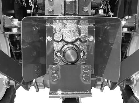
Power Take Off Guards
Warning
Do not remove the PTO guard. If the PTO guard must be moved upward or removed due to installation of attachment such as pump, be sure to install an extended shielding equivalent to the PTO guard to the attachment.
Also, install the PTO guard and PTO shaft cap to the original position immediately after the attachment is removed. Otherwise, it could cause serious injury or death due to entanglement.
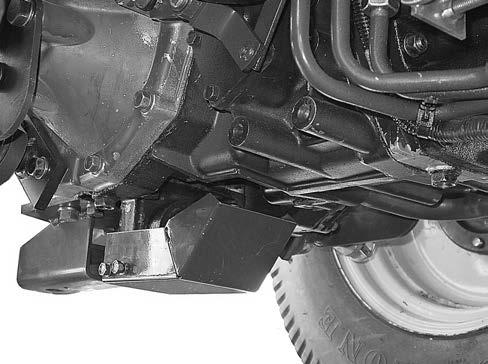
All tractors have a safety guard for the Rear PTO shaft and safety cover for the Mid PTO shaft.
Stationary Rear Pto Work
Caution
Be sure to move the Mid PTO control lever to the OFF position before leaving the operator’s seat.
Otherwise, the safety system will stop the engine automatically and the battery will run down or be dead.
According to the following instructions, use the Rear PTO for chipper, pump, or other stationary implements.
In this way, only the Rear PTO can be used.
1. Set the blocks at the tires.
2. Sit on the operator’s seat.
3. Apply the parking brake.
4. Make sure the all operating control levers are in “N“ or “OFF“.
5. Depress the clutch pedal and start the engine.
6. Shift the Rear PTO control lever to “ON”.
7. Adjust the proper engine speed for the Rear PTO work.
8. Leave the operator’s seat.
Pto Operating Safety
Warning
Be sure to move the PTO control lever to the OFF position and stop the engine and allow all rotating components to come to a complete stop before working on or near the PTO shaft, or servicing, inspecting or cleaning the PTO driven implement. Otherwise, it could cause serious injury or death.
When getting off the tractor with the PTO in operation during the stationary PTO work, always apply the tractor parking brake, place chocks behind and in front of the rear wheels, and stay clear of all the moving parts. Never step over rotating parts. Otherwise, it could cause serious injury or death.
For the safe operation of the PTO, follow these safe operating procedures.
Three Point Hitch Connecting Implements
1. Connect the implement to the hitch. See THREE POINT HITCH SYSTEM in this manual.
2. Connect the implement driveline to the tractor.
3. Check the driveline for correct length and for free telescopic movement by lifting and lowering hitch system. The correct length is important to prevent the driveline from hitting bottom or from separating in any tractor implement operating position.
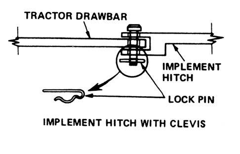
Drawbar Connecting Implements
1. Connect the implement hitch to the drawer with a hardened steel pin. Make sure the pin is securely held in place with a cotter pin or lock pin and does not make contact with the implement driveline.
2. Connect the implement hitch to the tractor drawbar before connecting the implement driveline to the PTO.
3. Connect the implement driveline to the tractor. Check the driveline for correct length and for free telescopic movement. The correct length is important to prevent the driveline from hitting bottom or from separating in any tractor or implement operating position.
IMPORTANT: Follow the implement manufacturers recommendations in adjusting and aligning the implement and implement driveline with the tractor.
Operating Instructions
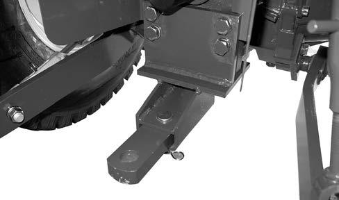
DRAWBAR
WARNING
When a heavy implement is installed to the drawbar, add front end weights to the tractor to keep balance.
Otherwise, the tractor could roll backward. Engage the clutch smoothly and use the brakes cautiously during traction. When the implement is raised, the implement may not stabile. Travel slowly, regardless of how much ballast is used.
Otherwise, it could cause an accident due to jerking and jackknifing. Be sure to use the drawbar for traction. Use 3 Point hitch only with a traction implement designed for its use not as a drawbar. Never pull other points other than above. If not use the drawbar or 3 point hitch, rear upset may happen.
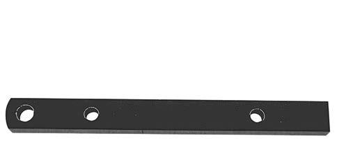
Your tractor is equipped with a drawbar. Use the drawbar for connecting all pullbehind implements.
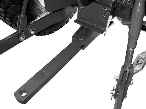
Drawbar Operating Position
STORAGE PIN HOLE (WITHOUT MID PTO)
DRAWBAR HITCH
CONNECTING PIN HOLE G
The drawbar must be in the storage position when using the three-point hitch.
[WITH MID PTO]
STORAGE POSITION (WITH MID PTO)
[WITHOUT MID PTO]
Operating Instructions
Connecting Implement To Drawbar
The correct connection of the implement to the drawbar will prevent stress on both the tractor and the implement. To assure proper tractor operation and optimum implement performance, the implement must be connected to the drawbar correctly.
1. Connect pull-behind implements to the drawbar only.
2. Use a hardened steel hitch pin to connect the implement to the drawbar. Make sure the pin is held securely in place with a lock pin.
STORAGE POSITION (WITHOUT MID PTO)
3. When working with the drawbar, raise the lower links as high as possible to prevent interference between the lower links and the implement.
Operating Instructions
4. The drawbar provides the standard hitch distance from the end of the PTO shaft to the centerline of the rear hole in the drawbar. This is necessary for safe PTO operation of trailing type equipment.
REAR PTO SHAFT
Safety Chain
When towing equipment on a highway, use a safety chain as an auxiliary connection between the tractor and the towed equipment. The safety chain must have a rating greater than the gross load of the towed equipment. Connect the chain to the tractor drawbar support and the towed equipment as shown in the illustration. Check the adjustment of the safety chain by turning the tractor completely to the right and left. Adjust the chain as necessary.
DRAWBAR
IMPORTANT: The maximum fixed drawbar vertical load is 325 kg(715 lbs)
SAFETY CHAIN
Field Operation
Three Point Hitch System
The three point hitch system gives position control of implements. This tractor is equipped with a category I hitch.
Hitch System Adjustments
The upper and lower links must be adjusted correctly so the implement can work at the needed depth and the links are free to move up and down with the shape of the ground.
LIFT LINKS
STABILIZERS
LOWER LINKS
Lift Links
1. Connect the lift links to the tractor and to the lower links. Make sure the lift links are installed on the proper side as shown.
2. The RH side lift link is adjustable by the turnbuckle to obtain the desired position of the hitch point. Turn the turnbuckle clockwise to shorten the link or counterclockwise to lengthen the link.
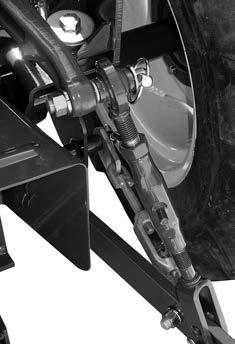
IMPORTANT: After the lift link is adjusted, make sure the locknut is tightened against the turnbuckle.
Upper Link
The length A of the upper link can be adjusted from 446 to 695 mm (17.6 to 27.4 inches).
Turn the turnbuckle clockwise to shorten the link or counterclockwise to lengthen the link.
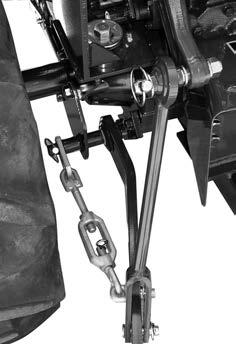
Stabilizer
When side movement of the hitch is undesirable or hazardous, the lateral swing is adjusted by the turnbuckle on the stabilizer.
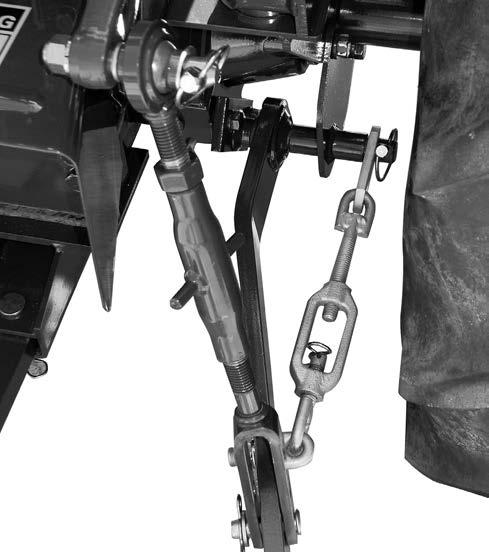
Turn the turnbuckle clockwise to lengthen the stabilizer or counterclockwise to shorten the stabilizer.
IMPORTANT: After the upper link is correctly adjusted, make sure the lock nut is tightened against the turnbuckle.
IMPORTANT: After making final adjustments carefully raise the implement to make sure that there is proper clearance between the implement and tractor components.
NOTE: Make sure the lock pin is installed after adjusting the stabilizer.
Telescopic Lower Links (IF EQUIPPED)
Telescopic Lower Links are provided for ease of hitching the implement as follows:
4. Connect telescopic lower links to the implement. Sit on Operator's seat and start engine.
5. Back tractor until each lock lever snaps and secures each telescopic lower link in the lock position.
1. Slowly back tractor into position to align the telescopic lower links with implement pins.
2. Park tractor safely.
3. Press the bracket (D) in telescopic lower link and pull link (E) to extend as needed.
Hitch Operation
Connecting Implement to Hitch
Warning
Be careful that no object exists between the tractor and implement when moving the 3 point hitch.
Keep well away from the linkage and implement when operating the 3 point hitch. Otherwise, injury may occure due to contacting with moving equipments. Clearance zone may not be obtained depending on the movement of the implement installed.
Usage varies from product to product. Use the implement by the proper method in accordance with the individual operator`s manual.
To connect an implement to the hitch, use the following procedure:
NOTE: Be sure the tractor and implement are on level ground.
1. Put the drawbar in the storage position.
2. Slowly move the tractor backwards to the implement.
3. When the hitch points on the tractor and implement are in the correct position, stop the tractor.
4. Apply the park brake and stop the engine.
5. Connect the implement to the Upper and Lower Links.
6. Adjust the Upper and Lower Links as necessary. See Hitch System Adjustments in this manual.
Disconnecting Implement from Hitch
To disconnect an implement from the hitch, use the following procedure:
NOTE: Be sure the tractor and implement are on level ground.
1. Stop the tractor completely and apply the park brake.
2. Disengage the PTO, lower the implement to the ground.
3. Gear Drive: Place the gear shift and range shift levers in Neutral.
Hydrostatic Drive: Release the speed lock lever, and place the range shift lever in Neutral.
4. Stop the engine and remove the key from the key switch before leaving the tractor.
5. Disconnect the implement from the hitch.
NOTE: Be sure the tractor and implement are stable and free from any tendency to roll over.
Hitch Control Lever
IMPORTANT: The position of the raise stop should not be set so rearward that a insufficient free play of the lift arms is available at the highest position when hitch control lever is moved until the lever is reached to the raise stop.
The hitch control lever is used to raise or lower the implement mounted to the three point hitch. To raise the hitch, move the lever to the rear. To lower the hitch, move the lever forward.
Adjustable stops are provided for use whenever it is desirable to return the hitch control lever to the same operating position.
Hitch Lowering Speed Adjustment
Warning
Do not leave the tractor with the implement lifted.
If the lifted implement is not lowered unexpectedly, it could cause serious injury or death.
If it is necessary to servicing, inspecting or cleaning the implement in the lifted position, stop the engine, set the hydraulic flow control knob to the LOCK position and move the hitch control lever forward to make sure that the implement does not lowered. Also, put jack stands under the implement. If the lifted implement is not lowered unexpectedly, it could cause serious injury or death.
Be sure to lift the implement and set the hydraulic flow control knob to the LOCK position when traveling the tractor. If the lifted implement is lowered unexpectedly, it could cause serious injury or death.
To adjust the hitch lowering speed, use the following procedure:
1. Move the hitch control lever forward to lower the implements.
2. Turn the hydraulic flow control knob to adjust the lowering speed. Turn the knob counter clockwise to increase the lowering speed. Turn the knob clockwise to decrease the speed or lock the hitch.
3. After adjusting the speed, raise the hitch and then lower it to check the speed.
3. After adjusting the speed, raise the hitch and then lower it to check the speed.
NOTE: When transporting the tractor on the road with the implement mounted on the three point hitch, always set hydraulic flow control knob to the LOCK position.
IMPORTANT: Never park a tractor with an implement in the raised position. Moving the hitch control lever forward will lower the implement even though the engine is not running. If it is necessary to service the implement in the raised position, use jack stands to safely block the implement in place. Put the hydraulic flow control knob in the LOCK position.
REMOTE HYDRAULIC CONTROL VALVE (IF EQUIPPED)
A double acting remote hydraulic control valve with a ''float position", is available from your Dealer.
If equipped, the control lever is located on the right side.
Connect the implement hoses to the remote hydraulic couplers so that the implement lowers when the control lever is pushed forward and raises when the lever is pulled rearward.
Switch the hoses if the implement works in the opposite way.
REMOTE HYDRAULICS OPERATION Float Operation
To operate the remote hydraulics in a float condition, move the control lever fully forward to the detent position. The lever will not return to neutral automatically when in the float position.
IMPORTANT: If implement is attached that has single acting cylinders, always use the "FLOAT" position when lowering. Continual use of the "LOWER" position will cause overheating and possible damage to the hydraulic system.
NOTE: The control lever for the remote hydraulic valve must be in the neutral for the three point hitch to operate.
IMPORTANT: Never park a tractor with an implement in the raised position. Moving the control lever forward will lower the implement even though the engine is not running. If it is necessary to service the implement in the raised position, use jack stands to safely block the implement in place. Put the hydraulic flow control knob in the LOCK position.
Hydraulic Block
A hydraulic block is located on the right side of the tractor. This block can provide an external hydraulic circuit for loader use or other applications. See your dealer.
IMPORTANT:
Remove the Plug P when the loader and the hydraulic block are used. Installing plug 1 to the Rc1/4. (tightening torque 21to29N•m{15to21Lb•ft})
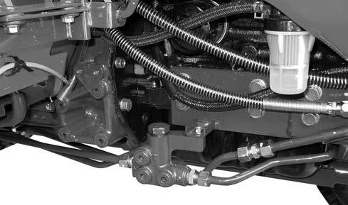
(Do not close the port in the hydraulic block when there is no plug 1.)
When Remote attachment is not installed, remove plug1. Afterwards, install Plug P. (tightening torque 49to58.8N•m{35to44 Lb•ft})
When the above is neglected, the hydraulic apparatus will be disadvantaged
Plug 1 is provided by the Loader manufacturer.
IMPORTANT: Never park a tractor with an implement in the raised position. Moving the hitch control lever forward will lower the implement even though the engine is not running. If it is necessary to service the implement in the raised position, use jack stands to safely block the implement in place. Put the hydraulic flow control knob in the LOCK position.
Adding Fluid after Connecting Cylinders and Hoses WARNING
When a cylinder or hoses is connected to the hydraulic system, cycle the control lever (such as the aux. valve levers, loader valve levers) more than five times to remove air from the cylinder or hose.
If there is air left in the cylinder or hose, the lifted implement could be lowered unexpectedly, causing serious injury or death.
Be sure to observe the following to prevent injury.
- Make sure that fluid lines and fuel lines are securely connected before applying pressure.
- Remove pressure completely from all the fluid lines before disconnecting them.
- Use safety goggles or other eye protection to check the leakage. Not use your hand.
Fluid Escaping hydraulic fluid under pressure from a pinhole may causes to penetrate skin.
If injured or allergic reaction by leaking fluid, see your doctor immediately. Be sure to lower the implement to the ground before disconnecting the cylinder or hose. If the lifted implement is lowered unexpectedly, it could cause serious injury or death. Do not leave the tractor with the implement lifted.
If the lifted implement is lowered unexpectedly, it could cause serious injury or death.
When servicing, inspecting or cleaning the implement in the lifted position, stop the engine, set the hydraulic flow control knob to the LOCK position and move the hitch control lever forward to make sure that the implement does not lowered.
Also, put jack stands under the implement. If the lifted implement is lowered unexpectedly, it could cause serious injury or death.
Operate the engine at a moderate idle speed. Set the stroke stop at the yoke end of the cylinder rod to provide maximum stroke. Then operate the cylinder in both directions about five times at least by moving the control lever up and down.
This will fill the cylinder and hoses with fluid and remove the air from the system. Fill the cylinder completely, stop the engine and check the fluid level with the transmission dipstick.
Add sufficient, clean specified fluid to bring the oil up to the proper level.
See TRANSMISSION AND HYDRAULIC LUBRICATION in this manual.
NOTE: If any of the hydraulic units are removed and replaced for any reason, check the oil level and add the specified fluid to the transmission to bring the oil up to the proper level.
TIRES/WHEELS/SPACING/BALLAST TIRE AND RIM EQUIPMENT Tire Inflation Specifications
Warning
Do not increase the inflation pressure beyond 35 psi.
Otherwise, the tire could explode during inflation, causing serious injury or death.
Do not damage the inflated or partially inflated tire. Otherwise, the tire could explode, causing serious injury or death.
Make sure that the tire is correctly seated on the rim before inflating. Otherwise, the tire could explode, causing serious injury or death.
Make sure that air is completely removed from the tire before removing it from the rim. Otherwise, the tire could explode, causing serious injury or death.
For normal tractor operation use the inflation pressure shown in the tire and wheel chart. The inflation pressure are based on cold inflation pressure recommendations by Tire and Rim Association Inc.
For maximum tractor performance, always adjust the tire pressure within the minimum/ maximum range to conform with the actual load on the tires. Under normal conditions, use the minimum pressure rating for general drawbar work. Use the higher pressure rating, up to the maximum, for heavy three point hitch mounted equipment, or heavy front and mounted equipment.
Example A shows the cross section of a tire inflated for maximum load but with a minimum load on the tire. The tire tread is not making full contact with the ground which will give poor performance.
Example B shows the cross section of a tire with inflated pressure correctly adjusted to the load on the tire. The tire tread is making full contact with the ground which will give maximum performance.
Tire pressure can also be adjusted as required to safety the following requirements.
A. Severe Service. Tire pressure can be increased 28 kPa (4 psi) more than the maximum pressure shown in the chart for tires used in severe service. Severe service includes the furrow tire in regular plowing operations, the downhill tire in plowing and in other hillside operations.
B. Tires With Liquid Ballast. Inflate the tires 14 kPa (2 psi) more than the recommended pressure. This will compensate for aeration that occurs when the tires are in motion.
IMPORTANT: During transportation on a railroad car or trailer, the tractor tires are often inflated to higher than normal operating pressures. Before using your tractor, check the air pressure in the tires to make sure that the air pressure does not exceed the maximum pressures shown in the tire and wheel equipment chart.
TIRES/WHEELS/SPACING/BALLAST
Tire Load Capacity
The maximum load capacity, shown in the tire pressure and load capacity chart, is of the wheel with the tire inflated to the maximum pressure. Do not exceed the maximum load capacity of the tire.
FRONT TIRE SIZETIRE RATING
AG. TIRES7 - 12 4PR
IND.TIRES23 x 8.50 - 124PR
TURF TIRES23 x 8.50 - 126PR
MAX. LOAD CAPACITY AT MAX. INFLATIO PRESURE
INFLATION PRESURE
REAR TIRE SIZETIRE RATING
AG. TIRES9.5 - 16 6PR
IND.TIRES12 x 16.56PR
TIRES33 x 12.5 - 16.54PR
MAX. LOAD CAPACITY AT MAX. INFLATIO PRESURE
INFLATION PRESURE
Check Air Pressure
Tire Pressure Check Interval
....Every 50 hours of operation or weekly.
Check the condition of the tires and rims for wear or damage. Keep the tires inflated to the recommended pressures. See Tire and Wheel Specifications in this manual for recommended inflation pressures for each tire size.
For tires equipped with liquid ballast, check the air pressure as follows:
1. Use an air-water gauge. The valve must be at the bottom of the tire to get an accurate reading.
2. Use a standard air gauge as follows:
A. The valve must be at the top of the tire.
B. Measure the rim diameter.
C. Add 3.5 kPa (1/2 psi) for each 305 mm (12 inches) of rim diameter to the standard gauge reading.