17 minute read
INSTRUMENTS AND INDICATORS


(1) Tachometer and Hour Meter
� The tachometer displays "Engine rotational speed / minute" (RPM).
� The symbol of the shape of the cogwheel directs the speed that uses appropriate PTO.
� The hour meter displays the engine driving time.
White line [A] shows the 540 rpm of the Rear PTO speed.
White line [B] shows the 2000 rpm of the MID PTO speed.
SYMBOL HOUR METER

(2) Engine Coolant Temperature Gauge
The gauge indicates the coolant temperature when the starter key switch is in ON position. If the engine overheats, the pointer turns the up side into position area. In this case, stop the engine immediately and check for the cause.
(4) Turn Signal Indicators
The LH indicator on the TACHOMETER will operate when the turn signal switch is moved to downward. The RH indicator will operate when the switch is moved to upward.
Both indicators will operate ON and OFF when hazard switch is pushed down.
(3) Fuel Gauge
The meter shows how much fuel is in the tank.
(5) Engine Glow Plug Indicator
This signal indicates the correct functioning of the glow plug circuit. When 10 seconds after the starter key switch turns to the ON position, or when the engine starts, the glow plug indicator lamp will be turned off.
NOTE: The pointer can be in lowest position when the starter key switch is in the OFF position. To get a fuel level indication, turn the starter key switch to the ON position.
(6) Charge Indicator
The charge indicator shows the battery is being discharged. If the lamp illuminates during operation, stop the engine and check for the cause.
(7) Engine Oil Pressure Indicator
The engine oil pressure indicator shows low engine oil pressure. If the engine oil pressure drops below its normal pressure, the engine oil pressure indicator will turn on. Shut off the engine immediately. Check for the cause.
Operating Controls
Control Switches
(1) Starter Key Switch
Position (HEAT) & (ON)
First position clockwise from OFF. In this position (Engine not running) energizes the glow plugs. The charge indicator, glow plug indicator and oil pressure indicator will illuminate.
The fuel gauge and temperature gauge will show correct values.
Position (START)
The starter key switch can be removed in the OFF position. Three switch positions are as follows:
Position (OFF)
Engine and all lamps except the hazard signal and flasher lamps are turned off.
Turn the key fully clockwise against the force of the spring in the switch. The starter motor will turn the engine. Release the key immediately when the engine starts.
NOTE: To prevent operation by persons not authorized and the possible discharge of the battery, remove the starter key when you leave the tractor.
IMPORTANT: Do not keep the starter key switch in the ON position for a long time when the tractor is not operating.
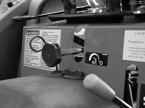
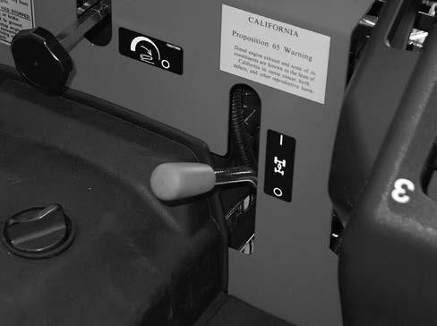
(2) Engine Speed Control Lever
Pull the engine speed control lever to the rearward to increase the engine speed. Push the engine speed control lever forward to decrease the engine speed.
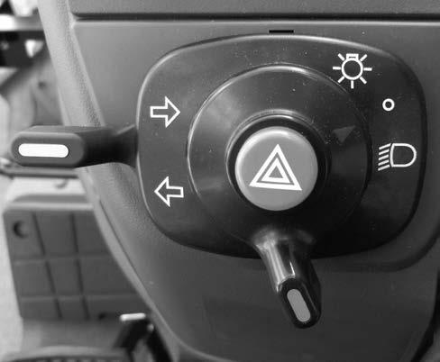
(3) Lamp Switch
Two position switch as follows: ALL lamps are OFF. (Turn signal, hazard signal and flasher lamps can be turned on.)
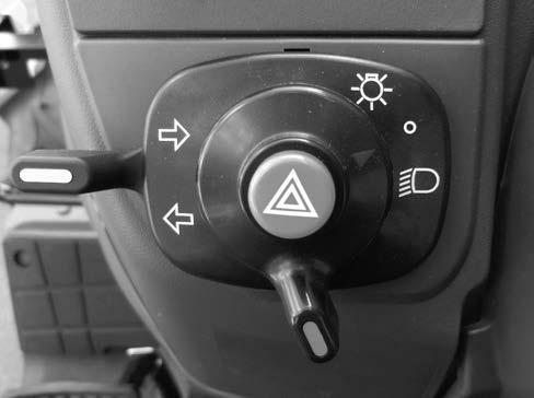
First position clockwise illuminates head lamps, instrument panel and rear red lamp.
(4) Hazard Switch
To flash the Flasher Lamps whenever the tractor is operated or traveling on roads.
(5) Turn Signal Switch
To indicate that you are going to turn the tractor to the RIGHT, move the turn signal switch to upward. To indicate that you are going to turn the tractor to the LEFT, move the turn signal switch to downward. Center position is OFF.
(6) Horn Switch
Press the horn switch to energize the horn.
Turn Signal with Hazard switch ON
When the turn signal switch is moved to upward, the RH flasher lamp will blink, and the LH lamp will stay ON.

When the turn signal switch is moved to downward, the LH flasher lamp will blink, and the RH lamp will stay ON.
Turn Signal with Hazard switch OFF
When the turn signal switch is returned to the center position, both flasher lamps will illuminate ON and OFF.
IMPORTANT: When towing an implement or wagon by the tractor, the complete rear area warning system (amber warning lamps, rear red lamp and SMV emblem) must be easily seen by any vehicle operator coming near the tractor.

Control Levers And Pedals
[Shuttle Type]
(1) Accelerator Pedal (Shuttle Type Only)
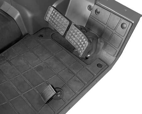
Use this pedal when operating the tractor on the road. Push the pedal down to increase engine speed.
NOTE: The engine speed control lever must be set to give the slowest engine speed when the throttle pedal is used.
(2) Speed Ratio Control Pedal (HST Type Only)
The control pedal is centralized to the neutral position by spring load. Push down on the front pedal to increase forward speed. Push down on the rear pedal to increase reverse speed.
(3) Brake Pedals
The pedals when locked together, provides braking to both rear wheels for stopping the tractor. When the brake pedals are unlocked, the pedals are used for individual braking of the rear wheels to aid in turning the tractor in soft soil conditions.
Push the RH brake pedal down to slow or stop the RH rear tractor wheel, push the LH brake pedal down to slow or stop the LH rear wheel. The tractor will turn in the direction of the wheel that is slowed or stopped.
(4) Brake Pedal Lock
Warning
Be sure to lock the 2 brake pedals by using the brake pedal lock to step on the pedals simultaneously when travelling on a road.
If the brake pedals unlocked when traveling road, brake will be applied unevenly, causing an accident.
When operating the tractor with extra weight applied or in a bad traction condition such as mud or ice, apply brake earlier than usual. Liquid in the tires, ballast weight on the machine or wheels, or tank filled with fertilizer, herbicide or insecticide, etc. will cause extra weight.
Otherwise, it could cause an accident due to increased stopping distance.
The brake pedal lock is located at the brake pedal arms and is used to lock the two brake pedals together so that both brakes are applied.
(5) Park Brake Lever
1. The park brake must be on to prevent movement of the tractor during stationary power takeoff work or when the tractor is parked. To engage the park brake, lock the brake pedals together, push down on the brake pedals and move the park brake lever upward. Push the brake pedal down to release the park brake.
(6) Speed Lock Lever
(HST Type Only)
To keep a constant forward travel speed, move the lever fully upward, while holding the speed ratio control pedal at the desired speed. It does not work in reverse.
2. Before getting off the tractor, disengage the PTO, lower all implements to the ground, place all control levers in their neutral positions, set the parking brake, stop the engine and remove the key.
3. If it is necessary to park on an incline, be sure to check the wheels to prevent accidental rolling of the machine.
[HST Type]
It is free on engine brake with the range lever engaged, be sure set the parking brake.
(7) Clutch Pedal
The clutch must be disengaged when starting the engine, stopping the tractor, storing the tractor and operating the following levers, gear shift lever, range shift lever Rear PTO lever, MID PTO lever, MFD lever, shuttle shift lever (Shuttle Type).
(8) Clutch Lock Latch
For long term storage, lock the clutch pedal in the disengaged position. This will prevent the clutch disc from sticking to the engine flywheel.
(9) DIFFERENTIAL LOCK PEDAL
Push the pedal down to engage the differential lock. A spring inside of the differential lock pushes it out of engagement when pedal is released.
[Shuttle Type]
NOTE: When engaging the differential lock, push the clutch pedal down or bring speed ratio control pedal to Neutral, to stop the wheels that are rotating, then push the differential lock pedal. Do not operate the differential lock pedal while the wheels are rotating.
WARNING
Do not engage the differential lock when travelling on a road or operating at a high speed.
Otherwise, the steering will be disabled, causing an accident.
(10) MFD Control Lever
To engage the MFD (Mechanical Front Drive), move the MFD control lever upward. Move the lever downward to disengage MFD (drive to the rear wheels only).
IMPORTANT: The clutch pedal must be pushed down to operate the MFD lever.
Control Levers
[Shuttle Type]
(11) Hydraulic Flow Control Knob
Use the hydraulic flow control knob to adjust the hitch lowering speed. Adjust the lowering speed to provide smooth operation of the hitch with the implement being used. Turn the knob fully clockwise to lock the hitch in position. See Hitch Lowering Speed Adjustment in this manual for more information.
(12) Gear Shift Lever (Shuttle Type Only)
The gear shift lever is used to shift the transmission gears into any of four speeds.
(13) Range Shift Lever
[Shuttle Type]
Move the range shift lever forward to place the transmission in H range. Move the lever rearward to place the transmission in L range.
(14) Shuttle Shift Lever
(Shuttle Type Only)
The shuttle shift lever is used to shift the transmission gear into forward of reverse position. Move the shuttle shift lever forward (F position) to the forward position. Move the shuttle shift lever rearward (R position) to the reverse position. The center position between F and R places the transmission in N position (Neutral).
[HST Type]
Move the range shift lever forward to place the transmission in H range. Move the lever to the rearward to place the transmission in L range. The center position between L and H places the transmission in N.
NOTE: Be sure the shuttle shift lever is in N (Engine start) position when starting the engine.
(15) Rear PTO Lever
Move the lever forward to engage the Rear PTO. Move the lever rearward to disengage the Rear PTO.
NOTE: Be sure the Rear PTO lever is in OFF position when starting the engine.
(16) Mid PTO Lever (IF EQUIPPED)
Move the lever forward to engage the Mid PTO. Move the lever rearward to disengage the Mid PTO.
(18) Remote Hydraulic Control Lever with Float Position (IF EQUIPPED)
A double acting remote control valve is available for your tractor.The remote hydraulic control lever which operates the remote control valve is located on the RH side fender.
See "remote hydraulic control valve" in this manual for more information.
NOTE:
1. Be sure the Mid PTO lever is in OFF position when starting the engine.
2. The Rear and Mid PTO shaft can be operated at the same time.
3. When not using the Mid PTO shaft, cover the shaft with the Mid PTO cover.
(17) Hitch Control Lever
Use this lever to control the position of the hitch. Move the lever forward to lower the Three point hitch. Move the lever to the rearward to raise the Three point hitch.
Operating Instructions
Operating Instructions
Before Starting The Engine
Before starting your tractor for the first time and before each operating period after that, make these checks:
1. Make sure all persons who operate or do maintenance on the tractor understand that clean fuel is important.
2. Check all lubrication fittings for grease as given in the Lubrication Chart.
3. Check the oil level in the engine crankcase. Check the oil level in the transmission.
4. Check the tractor fuel tank is filled with clean fuel that has the specifications given in this manual.
NOTE: Clean around the fuel tank cap before you remove cap.
5. Check the fuel system, cooling system and engine oil pan for leaks.
6. Check the fan belt is adjusted correctly.
7. Remove any water or sediment from the fuel filter cup.
8. Check the air pressure of the tires.
9. Make sure the PTO safety guard is installed.
10. Check the coolant level in the radiator and reservoir bottle. Add water and ethylene glycol coolant as needed.
Operating Instructions
RUN – IN PROCEDURE
If run-in instructions for a new engine are not followed, you can cause damage to position rings and cylinder walls.
Load
Never operate an engine immediately under full load. Allow the engine to warm up before operating it at full load. Run-in the engine carefully as shown in the table.
FRONT FRAME BOLTS
After the first 10 hours of operation, check the front frame bolts. Tighten the bolts to the torque shown below.
Front frame mounting torques
Size M12x30,35, 12Bolts
................................107.8 N•m (80Lb•ft)
LOWER LINK BRACKET BOLTS (P53)
After the first 10 hours of operation, check the Lower Link Bracket bolts.
Tighten the bolts to the torque shown below.
Size M12, 4Bolts
.................83 to 93 N•m (62 to 69 Lb•ft)
Size M14, 4Bolts
.............120 to 130 N•m (89 to 96 Lb•ft)
No Load
Do not run the engine at idle speed. When not operating the engine with a load, you can keep the correct engine operating temperature if you run the engine at approximately 1500 RPM.
Rear Wheel Bolts
After the first 10 hours of operation, check the rear wheel bolts. Tighten all wheel bolts to the torque give in the Wheel Mounting Torques in this manual. (P66)
Front Wheel Bolts
After the first 10 hours of operation, check the front wheel bolts. Tighten the bolts to the torques shown in the Wheel Mounting Torques in this manual. (P66)
Normal Starting Procedure
IMPORTANT: It is very important that enough lubricant reaches the engine parts before operating the engine at rated speed.
WARNING
Be sure to sit on the operator’s seat when starting the engine and operating the tractor. Otherwise, it could cause an accident.
Operating Instructions
1. Put the gear shift lever in the Neutral position (Shuttle Type) or the Speed Lock Lever to be released (HST Type).
WARNING
Make sure that all the operating controls are set to the neutral, lock position or off position before starting the engine. Otherwise, the tractor could move or the driven implement could start unexpectedly, causing an accident.
2. Put the REAR PTO and MID PTO control levers (If equipped) in the OFF (Engine start) position.
5. Put the engine speed control lever at the low speed position.
3. Put the SHUTTLE lever in the N (Engine start) slot (Shuttle Type).
6. Push the clutch pedal down.
4. HST control pedal in the N position (Engine start) (HST Type)
7. Turn the starter key switch to the heat & ON position. Wait until the glow plug indicator lamp is put out.
8. Turn key switch to start position until engine starts, but no more than 10 seconds, then release the key. Run engine for two minutes at 1500 RPM.
IMPORTANT:
1. If the engine starts and then stops, wait for the starting motor to stop turning before you turn the key switch to START position again.
2. Do not use the starter motor for more than 10 seconds without stopping. Wait one minute between starts so the starter motor can cool.
3. If engine stops when operating with a load, immediately start the engine again to prevent overheating caused by stopping the flow of oil for cooling and lubrication.
9. When the engine starts, check the oil pressure indicator, If the indicator stays on, stop the engine and find out what is wrong.
NOTE: If the oil pressure indicator stays on after the engine starts, stop the engine and check the oil level in the crankcase. Add oil if necessary. Start the engine, if the indicator is still on, do not operate the engine. Operating the engine without oil pressure will damage engine bearings and other engine parts. See your dealer.
4. If the charge indicator comes on during operation, determine and correct the cause to avoid complete discharge of the battery and possible damage to other components of the electrical system. See your Dealer.
5. If the coolant temperature gauge points at “ ” position, remove the load and allow the engine to run at 1500 rpm until the gauge goes down. If the gauge does not go down within one minute, stop the engine and determine the cause.
Starting Procedure for Hydrostatic Drive Tractors After Transporting on Truck or Flatcar
IMPORTANT: Hydrostatic transmission can jump into gear without warning, if the fluid leaks out of the control system. This can occur due to vibration if the tractor is transported on a truck or rail car. It can also happen if the transmission is drained or if the tractor sit still for very long periods. If any of these have happened, start the tractor as follows:
1. Put the range shift lever into the N (Neutral) position and release the speed lock lever to permit the speed ratio control pedal to return to N (Neutral) position.
2. Lock the brake pedals together, press down on the brake pedals.
3. Pull the engine speed control lever and start the engine. Set the engine speed to about 1000 RPM.
4. Slowly move the range shift lever to H range for high speed engagement.
If gear clash is obvious, the engine should be shut off immediately and the tractor unloaded by other means. Tow the tractor with the range shift lever in N (Neutral) to an area where the transmission can be checked by your Dealer. Refer to Towing the Tractor in this manual. (P39)
Cold Temperature Operation
To start and operate your tractor during cold ambient temperatures, use these procedures:
1. BATTERY – Must have a full charge.
2. FUEL – Must be clean and with no water.
3. ENGINE OIL – Must have the correct viscosity for the ambient temperature range.
4. TRANSMISSION HYDRAULIC FLUID –See lubrication table in this manual.
5. COOLING SYSTEM – Must have ethylene glycol solution for protection.
6. TIRES – If there is liquid in the tires, the tires must have protection against temperatures below 0°C(32°F). See your Dealer.
7. STOPPING THE ENGINE – Run the engine at idle speed for a short period of time to permit the engine temperature to decrease before stopping.
8. CONDENSATION IN FUEL TANK – To prevent condensation in the fuel tank and water entering the fuel system, fill the fuel tank after each operating day.
9. FUEL FILTER CUP – During cold ambient temperatures, make sure you remove water from the fuel filter cup each day.
If there is no obvious gear clash, drive the tractor in the normal manner.
NOTE: Do not use ether as a cold temperature starting aid.
IMPORTANT: During cold ambient temperatures, never run the engine at low idle speed for long periods of time.
During cold ambient temperatures, the engine will not heat to or keep the rated operating temperature can cause damage to the engine. Use the following procedures to warm the engine and transmission oil, and to keep the correct operating temperature.
10. WARMING THE ENGINE AND TRANSMISSION.
A. To heat the transmission oil to operating temperature, run the engine at 1500 RPM for approximately five minutes.
IMPORTANT: Operating the tractor with cold transmission oil can cause rough tractor operation with possible injury to the operator.
11. KEEP THE ENGINE AT CORRECT OPERATING TEMPERATURE.
A. Never run the engine below 1500 RPM.
B. Put a cover in front of the grille to control the amount of air going through the radiator.
12. STOPPING THE ENGINE
A. Run the engine at slow speed for a short period of time. This will permit the engine temperature to decrease gradually before stopping the engine.
Stopping The Engine
IMPORTANT: When stopping the engine after operating under heavy load, run the engine at 1500 RPM for a short period of time. This will allow the engine temperature to decrease gradually.
1. Move the engine speed control lever to run engine at low speed position for three to five minutes to decrease the temperature of engine.
2. Put the REAR PTO control lever, MID PTO control lever (If equipped) and the range shift lever in the OFF or N (neutral) position.
Operating Instructions
3. Turn key switch to OFF position. Remove the key.
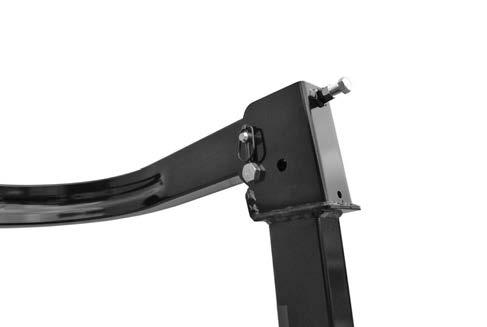
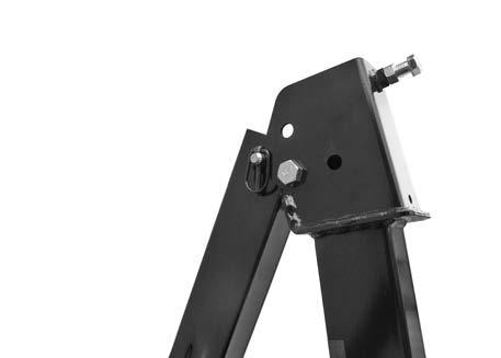
FOLDABLE ROPS FRAME
Holding and Adjustment
REGULAR POSITION
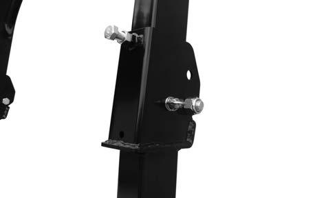
ROPS BAR
1. Loosen the lock nut and the lock bolt.
LOCK NUT LOCK BOLT
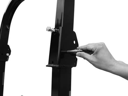
2. Remove the lock pin from the position pin.
LOCK PIN
POSITION PIN
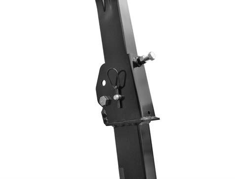
3. While holding the ROPS bar CAREFULLY remove the position pins.
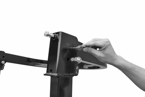
POSITION PIN
Operating Instructions
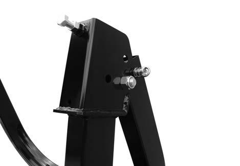
SECOND POSITION
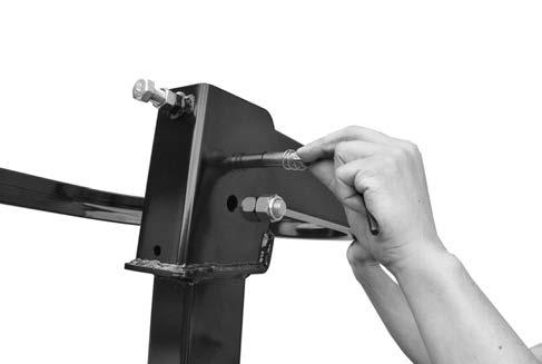
4. Down the ROPS bar slowly for the second position. While holding the ROPS bar carefully install the position pins.
POSITION PIN
5. Install the lock pin to the position pin.
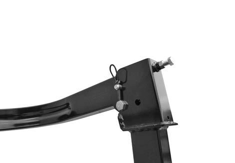
6. Remove the lock pin from the position pin.
POSITION PIN
LOCK PIN
7. While holding the ROPS bar CAREFULLY remove the position pins.
POSITION PIN
LOCK PIN
Operating Instructions
8. Down the ROPS bar slowly from the second position. While holding the ROPS bar carefully install the position pins.
Stored Position Position
Adjustment of Foldable ROPS.
If you feel less friction when the ROPS is at the upright position, tighten the Lock Nut until you feel the right friction in the movement.
Warning
Make sure that the ROPS frame is securely fixed with the lock pins before starting operation for roll over protection. Before proceeding to fold ROPS, check for any possible interference with installed implements and attachments. Otherwise, it could cause an accident, resulting in injury or death when the tractor rolls over or turns over due to improper operation.
NOTE: Genuine parts such as lock pin is available from your dealer.
Towing The Tractor
Warning
Do not use heavier trailed vehicle than towing tractor in case the vehicle has not own brake. Otherwise, it could cause an accident due to increased stopping distance.
When towing a tractor use the following procedures:
1. Make sure all controls are in the neutral position and the park brake is disengaged.
2. Use a rigid tow bar and safety chains to pull the tractor. Attach the tow bar and safety chains to the front tow hook.
3. Do not pull the tractor faster than 5 km/h (3 mph).
4. Disengage the mechanical front drive (MFD).
5. Disengage the differential lock.
6. [Shuttle Type]
Make sure the shuttle lever and the main shift lever are placed in the neutral position. [HST Type]
Make sure the HST pedal and the sub shift lever are placed in the neutral position.
IMPORTANT: When the engine is not running, there is no power assistance to the steering.
Use extreme caution when towing with the engine stopped.
NOTE: Check brake operation.
Operating Instructions
How To Transport Tractor
Warning
Load and unload with presence and induction of assistant.
Keep the tractor clear of children and people. Use a non-slip step with sufficient strength, width (sufficient for wheels not coming off), length (four time higher than the height of loading platform), and hook.
Load and unload in flat place where the step does not incline by the weight of tractor. Hang the hook of step straight against the loading platform so that there is no gap with the loading platform and it does not scoot down.
Do not change the driving direction on steps. Keep the tractor moving in the center of the steps. Serious accident and personal injury may occure by falling from the steps if the operator fails to do so.
If the tractor requires to change the driving direction on steps, unload the tractor from the steps and adjust the direction.
Do not use the main shift lever, clutch pedal, differential lock, and single brake during loading and unloading to the vehicle. The tractor may suddenly turn or fall.
Load in reverse and unload in forward at low speed. Also, do not operate the steering wheel unnecessarily.
When transporting the tractor on the track, apply parking brake and fix it with ropes.
1. Use a vehicle which does not exceed its laden weight and is the sufficient size for not sticking out a part of the tractor when a tractor is loaded. Stop the engine of the vehicle, set the gear shift to “1” or “Reverse”, apply parking brake, and place a wheel chock.
2. Use a non-slip step with sufficient strength, width (sufficient for wheels not coming off), length (four time higher than the height of loading platform), and hook. Hang the hook of step straight against the loading platform according to the gap with tread of tires of tractor.
Specifications for step
Length
Four times higher or more than the height of the loading platform of vehicle
WidthMore than 23.6 in {60cm}
Quantity2
Strength 1 step is resistant enough for weight over 3308 lbf {1,500 kg}