17 minute read
LUBRICATION/MAINTENANCE


6. Hoses and Connections between Air Cleaner and Manifold.
Inspect for loose fit or leakage. See AIR INDUCTION SYSTEM in this manual.
7. Water Pump, Fan and Alternator Belt Tension.
Check the belt for tension, replace if necessary. See Fan Belt Adjustment in this manual.
Engine Lubrication
Service Specifications
Oil Level Check Interval
........................................................Daily
Oil Change Interval
.................Every 100 hours (See NOTE)
Oil Type
....See Lubrication Table in this manual.
Oil Capacity
Without Filter Change
................................3.2 Liters (3.4 QTS)
With Filter Change
................................3.7 Liters (3.9 QTS)
NOTE: Change the engine oil after the first 50 hours of operation and then use the regular change interval. Change the engine oil more frequently when the operating conditions are severe, such as, operating in very high or very low ambient temperatures, very dusty.
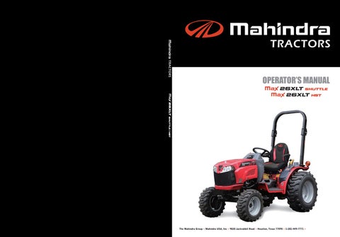
Engine Oil Level
To check the engine oil level, put the tractor on level ground and stop the engine. Pull the dipstick out, wipe the dipstick with a dry cloth and install the dipstick to check the oil level. If the oil level is below the A (Add) mark, add oil to raise the oil level to the F (Full) mark.
Do not raise the oil level above the F (Full) mark.
IMPORTANT: The level should be checked before starting or 5 minutes after the engine has been shut off.
Engine Oil Change
To change the engine oil, put the tractor on level ground and stop the engine. Change the engine oil as follows: NOTE: For best results change the oil while the engine is still warm.
1. Remove the oil pan drain plug and drain the oil from the engine.
IMPORTANT: Do not use the oil level dipstick as a guide when you fill the oil to engine crankcase . Always measure the amount of oil you install.
5. Start the engine. Operate the engine for five minutes at 1200 rpm. Check for oil leaks at the filter base and drain plug.
6. Stop the engine. Wait approximately five minutes for the oil return to the oil pan. Check the oil level on the dipstick and add oil if needed.
2. See Engine Oil Filter in this manual, if the filter needs to be changed.
3. Install the drain plug in the oil pan. Tighten the plug to a torque of 50 to 60 N•m (36 to 43 Lb•ft).
4. Put the correct type and amount of new oil into the engine. See Engine Oil Selection in this manual for the recommendation of oil type.
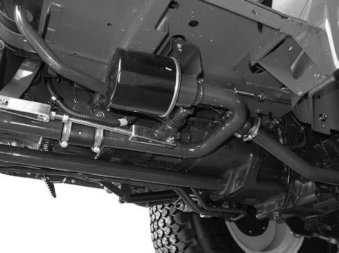
Engine Oil Filter
Change Interval
.................Every 100 hours (See NOTE)
NOTE: Change the engine oil filter after the first 50 hours of operation and then use the regular change interval.
IMPORTANT: Change the oil filter at the recommended time interval. Your Dealer has approved genuine filters. Do not use other type filters.
Change the engine oil filter as follows:
1. Drain the oil from the engine.See Engine Oil Change in this manual.
2. Turn the oil filter counterclockwise to remove. Use a filter wrench, if necessary.
4. Install the filter. Turn the filter until the O-ring comes in contact with the case surface. Tighten the filter an additional 2/3 turns by hand.
IMPORTANT: DO NOT use a filter wrench to install the oil filter. When the filter is too tight, you can cause damage to the O-ring and filter.
5. Put new oil in the engine. See Engine Oil change in this manual.
ENGINE COOLANT Service Specifications
Coolant Change Interval
.......Every 1000 hours or once per each year whichever occurs first.
Capacity of System
Engine and Radiator
................................5.0 Liters (5.3 QTS)
Coolant reserve bottle
................................0.6 Liters (0.6 QTS)
Thermostat
............76.5°C to 90°C (170°F to 194°F)
Radiator Cap Pressure
....................................88 kPa (12.8 psi)
Daily before starting the engine, check the coolant level the coolant reserve bottle. The coolant level should be between the "FULL" and "LOW" lines when the engine is cool.
Pressure Cooling System
WARNING
Be sure to cool down the cooling system before removing the radiator cap. After cooling down, turn the radiator cap to the first notch and wait until the pressure is completely removed.
Otherwise, hot coolant will blow out, causing burn injury.
1. The pressure cap on a pressure cooling system has a control valve that operates as a SAFETY RELIEF VALVE to keep the pressure within the system operating range. Operating the engine without a pressure cap or with a pressure cap but not setting value to operate at the correct pressure can cause damage.
2. A pressure cooling system decreases the loss of coolant caused by evaporation or boiling. The system must have good seals at the radiator cap, hoses and hose connections. It is important that you stop ALL LEAKS OF ANY SIZE as soon as the leaks are found. A small leak can become a large flow when pressure is increased in the cooling system. While the tractor is in operation, a weak hose can break and cause injury or damage. Check all hoses and hose connections with frequency. KEEP HOSES, HOSE CONNECTIONS AND PRESSURE CAP IN GOOD CONDITION.
Coolant Solutions
Your tractor cooling system is equipped with an ethylene glycol coolant solution that has a high boiling point.
IMPORTANT: Change the coolant solution at the change interval recommended in this manual (See Lubrication and service Chart). The heat generated by the diesel engine causes a natural change in the inhibitors in the coolant, which results in loss of corrosion protection. The loss of the inhibitors may cause water pump cavitations and cylinder block erosion.
Install only ethylene glycol coolant solution in the cooling system. Use a good quality, high boiling point, ethylene glycol that does not have any additives to stop leaks. Do not install any rust inhibitors that are not approved. It is possible that the rust inhibitors and ethylene glycol will not mix and work against each other to decrease corrosion protection, from deposits in the cooling system and cause damage to the cooling system and the radiator.
Do not use a low boiling point, alcohol type coolant solution.
The boiling point of alcohol is below the tractor minimum operating temperature; loss of coolant due to evaporation will result.
IMPORTANT: Always have a minimum of 50 percent ethylene glycol coolant in the cooling system at all times and at all ambient temperature ranges. Do not install more than 50 percent ethylene glycol in the cooling system unless the ambient air temperature will be less than -34°F. More than 50 percent ethylene glycol decreases heat transfer and will cause the engine surface temperature to be higher than normal.
Cleaning The Cooling System
IMPORTANT: NEVER PUT COOLANT IN A HOT ENGINE: THE ENGINE BLOCK OR CYLINDER HEADS CAN GET CRACKS BECAUSE OF THE DIFFERENCE IN TEMPERATURE BETWEEN THE METAL AND THE COOLANT.
Clean the cooling system each time when the coolant is changed. See the Lubrication and Service Chart in this manual for recommended change intervals. Clean the system as follows:
1. Remove the hose to drain the coolant. Close the plug after the system is empty.
3. Remove the radiator cleaner solution. Flush the system with clean water.
4. Fill the cooling system with the coolant solution specified in this manual. Install coolant system treatment (If required). See Coolant Solutions in this manual for more information. (P83)
5. Check the hoses, radiator, pump and water manifold for leaks.
IMPORTANT: Never drain the coolant when the engine is hot.
NOTE: After the cooling system is completely filled, run the engine for approximately five minutes to remove all air from the system. Check the coolant level and add coolant if needed.
2. Install a good type of radiator cleaner and fill the system with clean water. Follow the instructions given with the radiator cleaner.
Fuel System
Warning
Never refuel the machine when the engine is hot or running. Never smoke while refueling. Engine fuel is flammable and can cause a fire or an explosion. DO NOT fill the fuel tank or service the fuel system near an naked flame, welding, burning cigars, cigarettes etc.
Service Specifications
Fuel Filter Cup Service Interval
.......................................Every 10 Hours
Fuel Filter Element Change
...................Replace when loss of power or misfiring occurs
This type of filter cannot be cleaned. Change the filter when the engine is misfiring or a loss of power is evident. It is necessary to remove the air from the system after each replacement. Only a filter recommended by your Dealer should be used to be sure that it is both effective and capable of withstanding the required suction or pressure without damage to the filter element. Fill the fuel tank at the end of each day to reduce condensation.
NOTE: Do not fill the fuel tank to its full capacity. Space is required for vapor expansion in the event of a temperature change. A tank filled to capacity may overflow if exposed to a rise in temperature or direct sunlight.
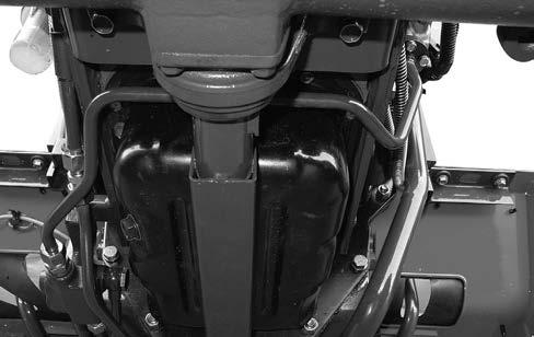
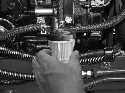
Water Removal from the Filter Cup
Before starting each day’s work, check for water or sediment in the filter cup. If water or sediment is in the cup, remove filter cup, clean and reinstall.
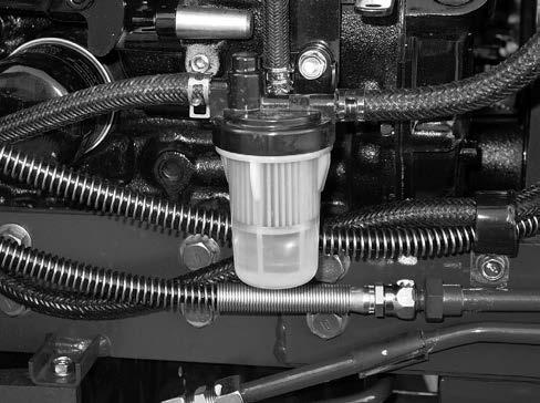
Filter Cup
NOTE: Be careful not to allow dirt, water and other foreign materials to get into the filter when cleaning the cup.
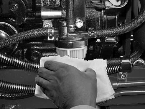
Fuel Filter Element Replacement
To replace the filter element, use following procedure:
1. Clean the outside of the filter body and cup to prevent dirt or foreign materials from entering into the system.
3. Install new filter element. Assemble filter cup and retaining nut to filter body.
2. Loosen the filter cup. Remove filter cup. Remove old filter element and clean inside of filter cup.
NOTE: Be sure O-ring is in place on the filter body and filter cup.
4. Clean off the fuel from the engine. Start the engine to check for fuel leaks around the filter, lines and fittings.
NOTE: If the engine does not have power with a full load after you have done the filter service and removed the air from the system, see your Dealer to find and correct the cause.
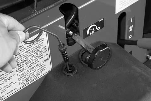
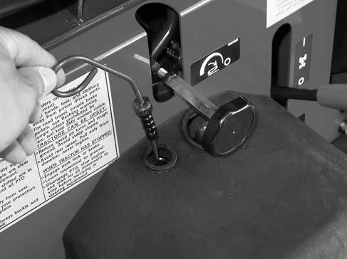
Fuel System Air Removal
AIR MUST BE REMOVED FROM THE FUEL SYSTEM.
AIR CAN ENTER THE FUEL SYSTEM
WHEN:
1. The engine stopped caused from lack of fuel.
2. The fuel filter has been replaced or the filter cup has been cleaned.
3. Any connections between the injection pump and fuel tank have been loosened or disconnected for any reasons.
4. The tractor has not been operated for long time.
5. The fuel pump has not operated correctly.
NOTE: This tractor has the function which discharges the air included in the fuel system automatically. The air exhaust procedure is as follows.
1. The starter switch is turned to the position of [ ]. Air will be discharged if it holds in the position as it is for 30 seconds.
LUBRICATION/MAINTENANCE
Fuel Injection Pump and Nozzle Check
Warning
Be sure to observe the following to prevent injury.
- Make sure that fluid lines and fuel lines are securely connected before applying pressure.
- Remove pressure completely from all the fluid lines before disconnecting them.
- Use safety goggles or other eye protection to check the leakage. Not use your hand.
Fluid Escaping hydraulic fluid under pressure from a pinhole may causes to penetrate skin.
If injured or allergic reaction by leaking fluid, see your doctor immediately.
The fuel injection pump and nozzles are precision units and must be serviced only by your dealer.
The injection pump is correctly set and sealed at the factory and should not require an adjustment. Whenever adjustment or repairs are necessary, see your dealer. Do not tamper with any of the pump units.
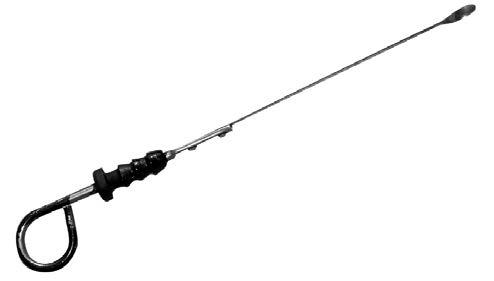
NOTE: Figure of the engine Unit
Air Induction System
The air induction system components require service at different intervals according to local operating conditions.
Service Specifications
Dump Valve
.................Clean daily or every 10 hours
Filter Element
Clean Element..............When necessary
Replace Element
......................After 10 cleanings or When necessary or yearly
System Inspection
..................Every 200 hours or yearly whichever occurs first Your tractor is equipped with a dry-type air cleaner with a replaceable element.
Dump Valve
The dust in the filter case should be dumped daily by using the dump valve when operating in extremely dusty conditions.
IMPORTANT: Service the air induction system at the given service intervals. Correct maintenance will make longer life of the engine. Keep all connections on the outlet hose tight.
Air Filter Element Removal
1. Stop the engine.
2. Open the hood and set the prop-rod.
3. When servicing the air filter element, unhook the clamp and remove element by pulling it straight out very carefully. Clean interior of canister.
Element Cleaning
Use clean, dry compressed air up and down the pleats on the clean side (inside) of the element.
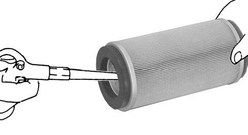
Continue this until the element is clean.
4.
NOTE:
1. The paper element must be handled with care. Do not hit the element against a hard surface.
2. Air pressure at the nozzle must not exceed 689 kPa (100 psi).
NOTE: Never attempt to remove the element from the air cleaner while the engine is running.
When installing the element, inspect the element gasket. If the gasket or element surface is damaged, replace the element immediately.
3. It may be necessary to replace the element sooner if the time interval between servicing becomes short indicating the element dose not respond to cleaning (soot contaminated).
System Inspection
Check the dump valve and the all hoses for cracks and wear. Replace if needed. All the connections on the hoses must be tight. All the gaskets must be in good condition and the bolts must be drawn up tight.
Transmission And Hydraulic Lubrication
Service Specifications
Oil Level Check Interval........................Daily
Oil Change Interval ...........Every 300 hours.
Oil Capacity
Gear Drive ..........22 Liters (23.2 Quarts).
Hydrostatic Drive
...........................23 Liters (24.3 Quarts).
Oil Type
Shuttle Type
...HYDRAULIC TRANSMISSION FLUID
HST Type
...HYDRAULIC TRANSMISSION FLUID
Hydraulic System Check
NOTE: Inspect the hoses and connections after the first 50 hours of operation and replace when necessary.
..............Yearly inspect for leaks, cracks and abrasion. Tighten fittings or replace as needed.
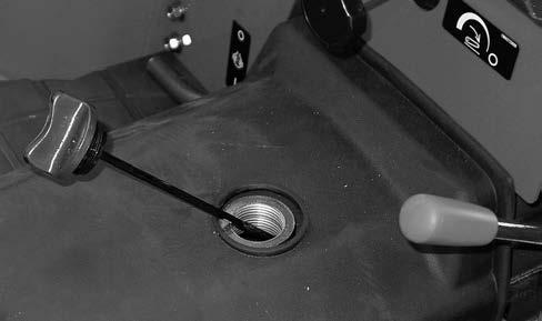
Transmission Oil Level
[Shuttle Type]
To check the transmission fluid level, put the tractor on level ground. Unscrew the filler cap with dipstick and wipe it clean. Check fluid by dipstick level, Do not screw in cap when checking. If the fluid level is below the lower line of the dipstick, add the recommended fluid to raise the fluid level between the F (Full) and L (Low) marked position.
Transmission Oil Level [HST Type]
Before checking the oil level of the hydrostatic drive tractor, run the engine for three to five minutes at 1500 RPM with the speed ratio control lever, range shift lever and PTO control lever in Neutral or OFF position. Afterwards, stop engine. Then check the oil level in the transmission.
Transmission Oil Change Oil Change Interval
.....................................Every 300 hours
To change the transmission oil, use the following procedure:
1. Put the tractor on level ground, apply the park brake and stop the engine. Move the range shift lever to L position.
2. Remove the drain plugs from the transmission case. (3 pieces)
To check the transmission oil level, put the tractor on level ground.
Check the oil level on the transmission dipstick. If the oil level is below the lower line of the dipstick, add the recommended oil to the transmission to raise the oil level to the F (FULL) marked position.
NOTE: For best results, drain the oil when the oil is warm.
3. Replace the hydraulic filter. See Hydraulic Filter in this manual.
4. For the hydrostatic drive tractor, replace hydrostatic filter if needed, See Hydrostatic Filter (HST Type) in this manual.
5. Install the drain plugs with a seal washer and tighten to a torque of 39 to 44 N•m (29 to 33 Lb•ft).
6. Add the recommended oil through the fill hole and check the oil level.
[Shuttle Type]
Hydraulic Filter
[Shuttle & HST Type]
Change Interval
.................Every 300 hours (See NOTE)
[HST Type]
7. Start the engine and check for leaks.
8. Recheck the oil level after stopping the engine. If the oil level is low, add oil up to the specified level.
NOTE: Replace the hydraulic filter after the first 100 hours of operation and every 300 hours of operation thereafter. Your Dealer has approved genuine filters. Do not use other type filters.
CHANGE THE HYDRAULIC FILTER AS FOLLOWS:
1. Put the tractor on level ground, move the range shift lever to the L position and apply the park brake.
2. Put an oil canister under the hydraulic filter.
3. Turn the filter counterclockwise to remove. Use a filter wrench if needed.
4. Apply clean oil to the O-ring on the new filter.
5. Install the filter. Turn the filter until the O-ring comes in contact with the case surface. Tighten the filter an additional 2/3 turns by hand.
IMPORTANT: DO NOT use a filter wrench to install the hydraulic filter. When the filter is too tight, you can cause damage to the O-ring and filter.
6. Wipe around the hydraulic filter with a dry cloth.
7. Change the transmission oil. See Transmission Oil Change in this manual.
Hydrostatic System Filter
[HST Type]
Filter Change Interval
.................Every 300 hours (See NOTE)
NOTE: Change the filter after the first 100 hours of operation and every 300 hours of operation thereafter. Replace the filter more frequently when operating under unusual dirt and dust conditions. Your Dealer has approved genuine filters. Do not use other type filters.
When the transmission oil filter needs changing, change the filter as follows:
1. Drain the transmission oil. See Transmission Oil Change in this manual.
2. Remove the hydrostatic system filter by turning it counterclockwise. Use a filter wrench, if necessary.
4. Install the new filter. Turn the filter clockwise until the O-ring comes in contact with the filter head surface. Tighten the filter an additional 2/3 turns by hand.
5. Add the transmission oil through the fill port and check the oil level.

6. Run the engine and check for leaks.
7. After stopping the engine, check the oil level. If it is low, add clean oil.
Hoses
DANGER: For fire prevention
Check if fuel is leaking from damages (crack, torn part, looseness of joint) of the fuel hose, peeling of external material and joint, and if leaking, replace it immediately to prevent fire.
WARNING: For burn, fire, and injury prevention
Check for looseness of joint of the radiator hose. If the radiator hose comes off during operation, hot water blows up.
Check for looseness of joint of the power steering hose and oil leakage. If oil leaks, the power steering does not function, causing an accident.
Service Specifications
Fuel hose and power steering hose change interval
..........................................Every 2 years
Inspection
Check the fuel hose, radiator hose, and power steering hose for fuel, water, and oil leakage due to deterioration and damages and the tightening band for slackness.
After Replacement of Power Steering Hose
After replacing the power steering hose, turn the steering wheel to left and right completely to release the air in the hydraulic circuit.
After Replacement of Fuel Hose
After the fuel hose is replaced, release the air. (see P87)
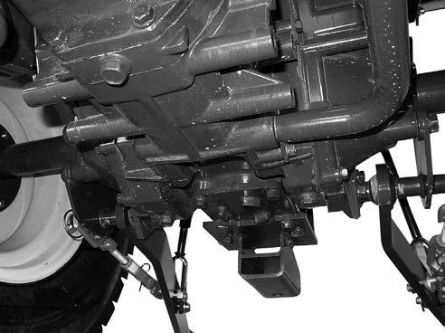
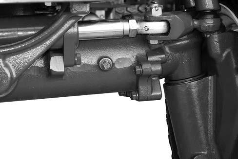
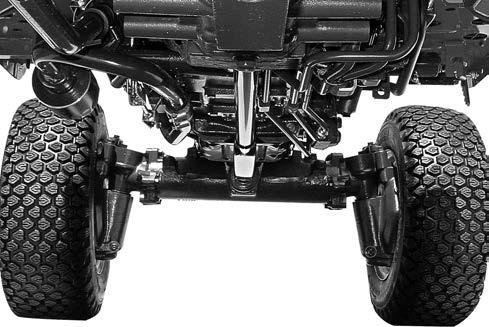
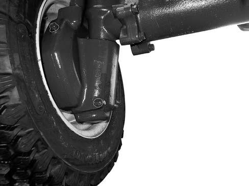
FRONT AXLE LUBRICATION (MFD)
Service Specifications
Oil Change Interval
.................Every 300 hours (See NOTE)
Oil Capacity ...............4.0 Liters (4.2 Quarts)
Oil Type .........Hydraulic Transmission Fluid
NOTE: Change the oil after the first 100 hours of operation and then every 200 hours of operation.
Front Axle Oil Level
To check the front axle oil level, put the tractor on level ground. Remove the oil level plugs located on the rear of the both gear cases. If the oil level is low, add the recommended oil type through the fill hole located on the RH side of axle housing until the oil begins to flow out of the level plugholes.
Front Axle Oil Change
1. To change the front axle oil, put the tractor on level ground. Put the range lever in L, engage the park brake and stop the engine.
2. Remove the fill cap located on the axle housing, the front axle drain plugs located on the bottom of both side gear cases to drain the oil.
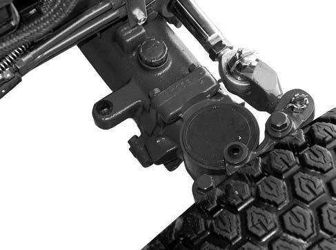
3. Install the both front axle drain plugs. Supply the oil of the specified quantity. Remove the ventilator cap of right side and left side.
Tighten the ventilator cap, after oil flows out.(During 20 seconds, oil flows out after having removed a ventilator bolt.) Afterwards,remove the oil level plug and confirm that oil flows out.
Finally, tighten the oil level check bolt.
VENTILATOR BOLT
DRAIN PLUG
NOTE: For best results, drain the oil when the oil is warm.
LUBRICATION/MAINTENANCE
Cooling System
Grill Screens and Radiator Area
Grille Screens and Radiator Area
Service Interval
................Every 50 hours or more frequently if required.
To clean the radiator screen, put the tractor on level ground, apply the park brake and stop the engine.
3. Clean the radiator screen and the surrounding area.
4. Install the radiator screen. Lower the hood.
Fan Belt Adjustment
Warning
Be sure to stop the engine and make sure that all the parts are completely stopped before starting adjustment. Otherwise, it could cause injury.
Fan Belt Tension Check Interval
............................Daily or after 10 Hours
NOTE: Adjust the belt tension after the first 50 hours of operation and replace when if needed.
Measure the fan belt for correct tension. Check to see if the belt deflection is about 5mm (0.2 inch) when pushing the belt with 49N{5 kg} (11 lb) load at point (A).
FAN PULLEY
Alternator Pulley
(A)
5mm (0.197 inch) 49N {5kg} (11 lb)
RADIATOR SCREEN
CRANK PULLEY
To adjust the fan belt tension, loosen the adjusting bolt and pivot nut of the alternator. Move the alternator away from the engine until as shown above. Tighten the adjusting bolt and pivot nut to a torque of 16 N•m (12 Lb•ft).
2. Loosen the alternator-adjusting bolt.
3. Loosen the alternator pivot nut and push the alternator toward the engine to remove the belt.
NOTE: Too high tension will cause alternator and water pump bearing failure and belt wear.
Too low tension will cause a decrease in alternator output and belt wear.
Fan Belt Replacement
To replace the fan belt, use following procedure:
1. Open Bonnet.
4. Install new fan belt and adjust the belt tension. See Fan Belt Adjustment in this manual for instructions.
Clutch Pedal Adjustment
Service Specifications
Clutch Pedal Check and Adjustment Interval
..............................Every 50 hours of operation or yearly
Free Pedal Movement
..........................20-30mm (0.8-1.2 inch)
Free Movement Adjustment
Clutch pedal free movement is very important and must be checked at the recommended intervals. If there is no free movement, the clutch disc will wear quickly. If there is too much free movement, the clutch will not disengage correctly and the transmission will be difficult to shift.
1. Put the tractor on level ground, move the range shift lever in the L position, apply the park brake, stop the engine and adjust the clutch pedal free movement as follows.
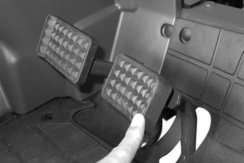
2. Push the clutch pedal down by hand, to measure the amount of pedal free movement.
3. The pedal free movement must be with in the specification shown above.
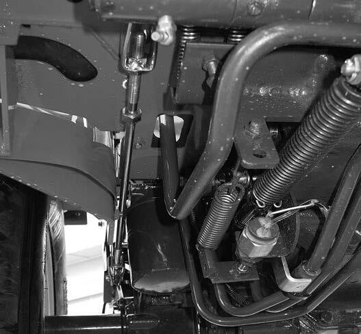
4. Loosen the lock nut.
5. Adjust the pedal free movement as necessary with the adjusting nuts on the clutch rod.
6. To increase free movement, turn the nuts at inside.
7. To decrease free movement, turn the nuts at outside.
8. Tighten the lock nuts to the torque of 44 to 54 N•m (32 to 40 Lb•ft).
20~30mm 20
BRAKE PEDAL ADJUSTMENT Service Specifications
Brake Pedal Check and Adjustment Interval
.........................Every 50 hours or yearly
Free Pedal Movement Specification
................40 to 50mm (1.57 to 1.97inch) at the brake pedal. With this free movement is obtained, tighten the lock nut.
Brake pedal free movement is very important and must be checked at the recommended intervals. If there is no free movement, the brake disks will wear quickly.
If there is too much free movement, accidents may occur. If there is not the same free movement between LH pedal and RH pedal, it may cause serious accidents.
Put the tractor on level ground, move the range lever in the L position. Stop the engine.
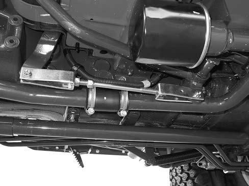
Loosen lock nut and rotate the brake rod to make a free play of 40 to 50 mm (1.57 to 1.97 inch.)
Confirm that the right and left brakes operate simultaneously by running the tractor.
If not, adjust both of them by means of the brake rods.
Raise Stop Setting Position
If raise stop setting position is incorrect, the hydraulic pump might be damaged. Therefore carefully adjust as below.
1. Disconnect an implement from the hitch. (See Disconnecting Implement from Hitch in this manual.)
2. Disconnect LH and RH lifts rods from the lift arms.
3. Start the engine.
4. Move the hitch control lever rearward to raise the lift arm to the maximum lifting position.
6. Check a free play of the lift arm to be 5 to 10 mm at the top of the lift arm by hands.
Max. position by hand position by hydraulic
A 5~10mm(0.2~0.4 in)
7. If the free play is insufficient, move the raise stop forward and check again with the same procedure as before.
5. With the arm so raised, stop the engine.