16 minute read
INSTALLATION


15.54” Outside to Outside
1710C
4.72
4.2.9. 1710C on these tractor models 2015 and 2216: Remove the following equipment from tractor: Remove belly mower (if so equipped) to allow backhoe to be installed. Park front end loader (if so equipped) during backhoe installation.
Loader Rear Ballast. Drawbar and Drawbar Bracket. Slow Moving Vehicle Sign. All 3-Point components. Tool Box.

Slow Moving Vehicle Sign Bracket.
Note: When backhoe attachment is parked from tractor, reinstall loader rear ballast, drawbar, Slow Moving Vehicle Sign, and 3-point upper, lower links and tool box to tractor before operating.
10.77”
1710 CTractor Models 2015 and 2216: Remove Tool Box and Slow Moving Vehicle Sign Bracket. Remove Slow Moving Vehicle Sign, All 3-Point Components, Drawbar, Loader Rear Ballast, and Drawbar Bracket.
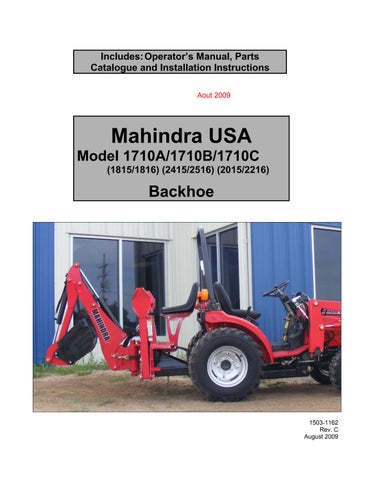
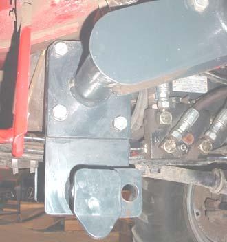
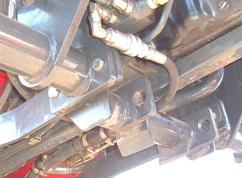
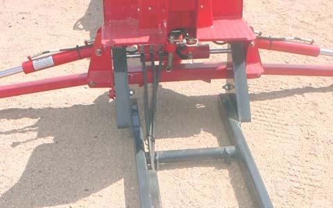
4.2.10. Install rear bracket to drawbar area of tractor using tractor casting mounting holes as shown in Photos A, B, & C.
Rear Casting Holes, 4 places.
Bottom Casting Holes, 4 places.
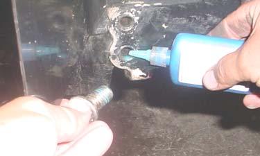
4.2.11. Clean all 8 rear bracket bolt threads and tractor drawbar internal casting holes with a degreaser, and allow threads to dry. After dry, apply 242/243 "Loctite" to both the bolt and internal casting threads. Reinstall bolts and torque to specifications. See Torque Chart, Page 89. This step is required to keep this hardware tight during loader and backhoe operation.
CRITICAL NOTE: "Loctite" must be applied to BOTH the bolt threads and the internal casting holes of tractor to allow the "Loctite" to work properly. Hardware must be reinstalled and torqued as specified before "Loctite" begins to setup.
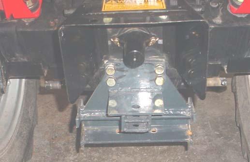
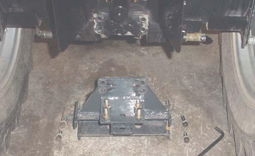
4.2.12. Install tractor supplied hex head cap screws and lockwashers in rear casting holes, 4 places as shown in photos B & C.
Rear Casting Holes.
Apply 242/243 "Loctite" to clean casting threads. Apply 242/243 "Loctite" to clean bolt threads.
Hex Head Cap Screw
14mm x 2.0P x 35mm Grade 8.8 and 14mm Lockwasher, 4 places (tractor supplied).
4.2.13. Install backhoe supplied socket head cap screws and lockwashers in bottom casting holes, 4 places as shown in photos B & C.
Socket Head Cap Screw
12mm x 1.75P x 30mm and 1/2 lockwasher, 4 places (backhoe supplied).
4.2.14. Torque all rear bracket mounting hardware to specifications. See Torque Chart, Page 89.
4.2.15. Place a mark on side of bolts and rear bracket with a permanent marker. This mark allows operator to have a quick visual check of hardware tightness.
Installation Instructions For Backhoe Model 1710c
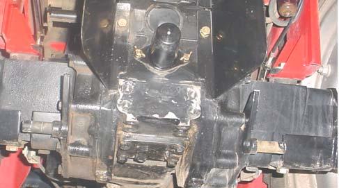
4.2.16. BACKHOE WITH LOADER: Remove loader center brackets from tractor, if preinstalled. Position backhoe center bracket to tractor with loader center brackets to the outside of backhoe center bracket. Secure using 14mm x 40mm hardware. Torque to specifications. See Torque Chart, Page 89.
Hex Head Cap Screw 14mm x 2.0P x 40mm Grade 8.8 (backhoe supplied) and 9/16" Lockwasher (loader supplied), 4 places.
Backhoe Center Bracket.
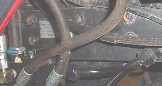
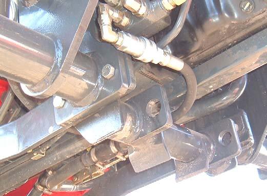
4.2.17. Service tractor engine rail bolts as follows: Clean one tractor engine rail bolt thread and tractor internal casting hole at a time with a degreaser, and allow threads to dry. After dry, apply 242/243 "Loctite" to both the bolt and internal casting threads. Reinstall bolt and torque to specifications. See Torque Chart, Page 89. Repeat until 4 bolts on each side of tractor are serviced. This step is required to keep this hardware tight during loader and backhoe operation.
CRITICAL NOTE: "Loctite" must be applied to BOTH the bolt threads and the internal casting holes of tractor to allow the "Loctite" to work properly.
NOTE: Hardware must be reinstalled and torqued as specified before "Loctite" begins to setup.
4.2.18. Place a mark on side of bolts and side rail with a permanent marker. This mark allows operator to have a quick visual check of hardware tightness. Service tractor engine rail bolts, 4 places each side.
Apply 242/243 "Loctite" to clean casting threads. Apply 242/243 "Loctite" to clean bolt threads.
RH Loader
Center Bracket.
NOTE: Backhoe Center Bracket Attaching Hole must be positioned toward front of tractor.
4.2.19. BACKHOE WITH LOADER PRE-INSTALLED: Remount loader to tractor at this time.
4.2.20. BACKHOE WITH LOADER TO BE INSTALLED: Complete installation of loader to tractor at this time.
BACKHOE MODELS 1710A / 1710B/ 1710C
4.2.21. Install backhoe subframe to backhoe. See page 21 and 24 for subframe identification. Secure using hex head cap screw 5/8”-11 x 1.75”, six places, stover hex locknut 5/8”-11, 6 places, and 5/8” hardened flatwashers on bolt head side and stover nut side, 12 places. See illustration below for hardware detail.
Hex Head Cap Screw 5/8”-11 x 1.75”, six places, Stover Hex Locknut 5/8”-11, 6 places, and 5/8” Hardened Flatwashers on bolt head side and Stover Nut side of these bolts, 12 places
5/8” Hardened Flatwashers on both sides of plates
Installation Instructions For Backhoe Models 1710a And 1710b
4.3. Connect Loader Valve Hydraulics
NOTE: If your loader is equipped with a Cross Loader Valve see ML104 Operators Manual form 1503-1183 or Supplemental Sheet form 1503-1182 for Return/Out port installation.
4.3.1. Remove loader valve from valve mount and remove and discard return hose from loader valve. Remove power beyond plug from RH side of loader valve.
NOTE: These instructions have been written as if loader has been pre-installed on tractor.
Loader Return Hose Power Beyond Plug
4.3.2. Install o-ring into o-ring groove in power beyond port of loader valve. NOTE: Position loader valve so power beyond port is facing upward. This will allow you to install o-ring correctly. Install power beyond plug into this port as shown.
Place O-Ring in the bottom of the groove
Thread Power Beyond Plug into Power Beyond port of Loader Valve

NOTE: O-ring must be installed correctly for proper hydraulic operation.
O-ring installed in Power Beyond port of Loader Valve
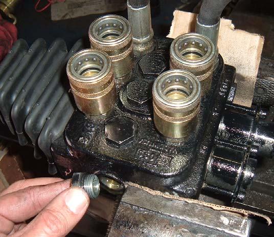
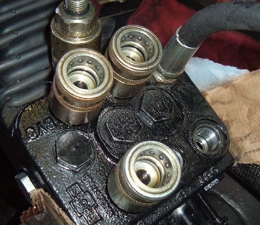
Remove this plug
Remove these Female Quick Couplers from loader valve. Reinstall after tee fitting has been installed
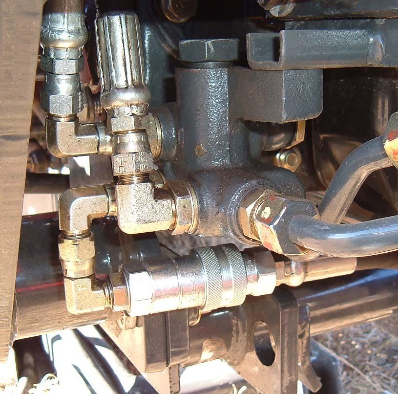
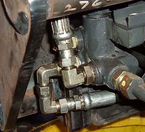
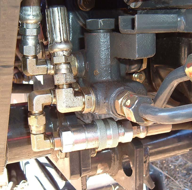
4.3.5. Reinstall loader valve to valve mount and install ¾” JICF x 9/16” JICF straight fitting and 9/16” ORBM x 9/16” JICM 45° fitting to tee fitting as shown. Install male quick coupler to o-ring end of 45° fitting as shown.
Male Quick Coupler

9/16” ORBM x 9/16” JICM 45° Fitting
¾” JICF x 9/16” JICF 180° Fitting
Tee fitting rotated outward slightly for correct hose routing
4.4. Connect Tractor Hydraulics
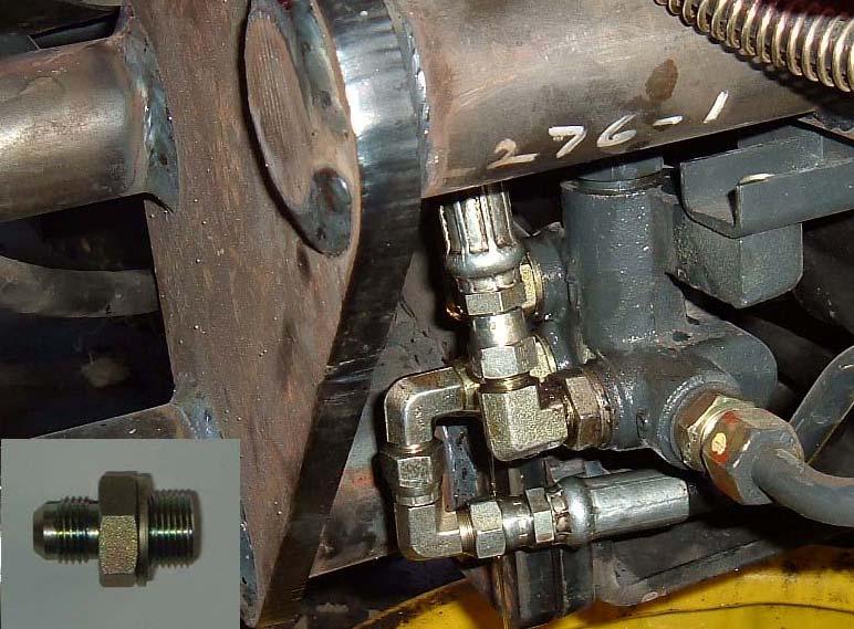
4.4.1. 1710A (1815/1816): Install backhoe supplied 3/8” x 47” hose assembly 9/16” ORBM x ¾” ORBM in power beyond “BYD” port of loader valve. Install male quick coupler to opposite end of this hose.
3/8” x 47” Hose Assembly 9/16” ORBM x ¾” ORBM
1710A and 1710B Tee Fitting rotated outward slightly for correct hose routing
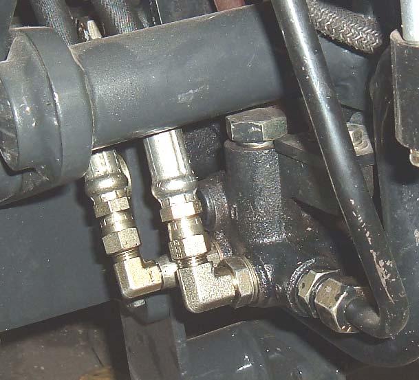
4.4.2. 1710A (1815/1816): Remove plug from return “T” port of tractor hydraulic block.
NOTE: To improve access to return “T” port, you may need to remove loader power beyond hose from 90° fitting installed in Tractor Power Beyond “N” port.
Remove plug from return “T” port of tractor hydraulic block
Loader Power Beyond hose
4.4.3. 1710A (1815/1816): Install 3/8” BSPTM x 9/16” JICM straight fitting into return “T” port.
3/8” BSPTM x 9/16” JICM Straight Fitting (Backhoe Suplied)
4.4.4. 1710A (1815/1816): Remove pressure hose from 9/16” JICM x 9/16” JICF fitting installed in pressure “P” port of tractor hydraulic block. Rotate fitting as shown and route pressure hose around center bracket rod.
Center Bracket Rod
Rotate fitting and route pressure hose as shown

4.4.5. 1710A (1815/1816): Remove loader supplied 9/16” JICM x 9/16” JICF 90° fitting installed in power beyond “N” port of tractor hydraulic block and install this fitting on straight fitting installed in return “T” port of tractor hydraulic block. Install backhoe supplied 9/16”
ORBM x 9/16” JICF 90° fitting on straight fitting installed in power beyond “N” port of tractor hydraulic block. Install female quick coupler on this fitting. Rotate this fitting as shown.
9/16” JICF x 9/16” JICM 90° fitting (Loader Supplied)
9/16” ORBM x 9/16” JICF 90° fitting(Backhoe Supplied)
Female Quick Coupler (Backhoe Supplied)
Return Hose to Loader Valve
4.4.6. 1710A (1815/1816): Install backhoe supplied 3/8” x 27” hose assembly ¾” JICF x 9/16” JICF to tee fitting installed in return “Out” port of loader valve.
3/8” x 27” hose assembly ¾” JICF x 9/16” JICF
Tee fitting rotated outward slightly for correct hose routing
4.4.7. 1710A (1815/1816): Connect the remaining end of backhoe supplied 3/8” x 27” hose assembly ¾” JICF x 9/16” JICF to 9/16”
JICF x 9/16” JICM 90° fitting installed in return “T” port of tractor hydraulic block.
3/8” x 27” hose assembly ¾” JICF x 9/16”
JICF
9/16” JICF x 9/16” JICM 90° fitting
4.4.8. 1710A (1815/1816): Connect male quick coupler on the end of the 3/8” x 47” Hose Assembly 9/16” ORBM x ¾” ORBM installed in the power beyond “BYD” port of the loader valve to the female quick coupler installed in the power beyond “N” port of the tractor hydraulic block to complete installation.
3/8” x 47” Hose Assembly 9/16” ORBM x ¾” ORBM
IMPORTANT: After installation check that tractor brake pedal components clear all loader and backhoe components. If contact occurs see tractor manual and adjust brake travel to eliminate contact.
NOTE: Tighten all hydraulic fittings and hoses at this time.
4.4.9. 1710B (2415/2516): Install backhoe supplied 3/8” x 65” hose assembly 9/16” ORBM x ¾” ORBM in power beyond “BYD” port of loader valve. Install male quick coupler to opposite end of this hose.
3/8” x 65” Hose Assembly 9/16” ORBM x ¾” ORBM
4.4.10. 1710B (2415/2516): Remove plug from return “T” port of tractor hydraulic block.
NOTE: To improve access to return “T” port, you may need to remove loader power beyond hose and 90° fittings installed in Tractor Power Beyond “N” port.
Remove plug from return “T” port of tractor hydraulic block
Loader Power Beyond Hose and 90° Fittings

4.4.11. 1710B (2415/2516): Install 3/8” BSPTM x 9/16” JICM straight fitting into return “T” port.
3/8” BSPTM x 9/16” JICM Straight Fitting (Backhoe Supplied)
(2415/2516):
4.4.13. 1710B (2415/2516): Remove bottom loader supplied 9/16” JICM x 9/16” JICF 90° fitting installed in power beyond “N” port of tractor hydraulic block and install this fitting on straight fitting installed in return “T” port of tractor hydraulic block. Install backhoe supplied 9/16” ORBM x 9/16” JICF 90° fitting on remaining 90° fitting installed in power beyond “N” port of tractor hydraulic block. Install female quick coupler on this fitting.
Return Hose to Loader Valve
9/16” JICM x 9/16” JICF 90° fitting (Loader Supplied)
9/16” ORBM x 9/16” JICF 90° fitting (Backhoe Supplied)
Female Quick Coupler (Backhoe Supplied)
4.4.14. 1710B (2415/2516): Install backhoe supplied 3/8” x 35” hose assembly ¾” JICF x 9/16” JICF on tee fitting installed in return “Out” port of loader valve.
3/8” x 35” hose assembly ¾” JICF x 9/16”
JICF
Tee fitting rotated outward slightly for correct hose routing
4.4.15. 1710B (2415/2516): Connect the remaining end of backhoe supplied 3/8” x 35” hose assembly ¾” JICF x 9/16” JICF to 9/16” JICF x 9/16” JICM 90° fitting installed in return “T” port of tractor hydraulic block.
3/8” x 35” hose assembly ¾” JICF x 9/16”
JICF
4.4.16. 1710B (2415/2516): Connect male quick coupler on the end of the 3/8” x 47” Hose Assembly 9/16” ORBM x ¾” ORBM installed in the power beyond “BYD” port of the loader valve to the female quick coupler installed in the power beyond “N” port of the tractor hydraulic block to complete installation.
IMPORTANT: After installation check that tractor brake pedal components clear all loader and backhoe components. If contact occurs see tractor manual and adjust brake travel to eliminate contact.
NOTE: Tighten all hydraulic fittings and hoses at this time.
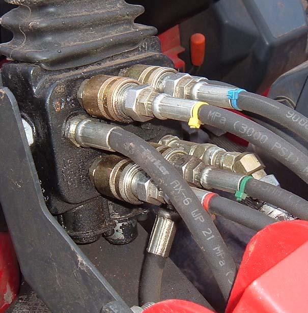
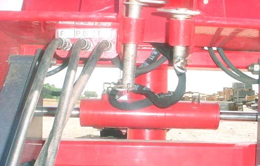
4.4.17. 1710A (1815/1816): Install following 3 hoses to backhoe as shown.
Mark both ends of Pressure "P" Hose
3/8" x 73" ORBM 9/16" x JICF 3/4" using red nylon ties then connect to backhoe
Mark both ends of Power Beyond "PB" Hose
3/8" x 90" ORBM 9/16" x JICF 3/4" using yellow nylon ties then connect to backhoe
Mark both ends of Tank/Out "T" Hose 3/8" x 112" ORBM 9/16" x JICF 3/4" using green nylon ties then connect to backhoe
4.4.18. 1710B (2415/2516): Install following 3 hoses to backhoe as shown.
Mark both ends of Pressure "P" Hose
3/8" x 57" ORBM 9/16" x JICF 3/4" using red nylon ties then connect to backhoe
Mark both ends of Power Beyond "PB" Hose
3/8" x 93" ORBM 9/16" x JICF 3/4" using yellow nylon ties then connect to backhoe
Mark both ends of Tank/Out "T" Hose
3/8" x 112" ORBM 9/16" x JICF 3/4" using green nylon ties then connect to backhoe
4.4.19. Route these 3 hoses through backhoe subframe channel.
4.4.20. Install female quick coupler to Pressure "P" Hose with red nylon ties.
(Connects to Loader Power Beyond Hose.)
4.4.21. Install male quick coupler to Power Beyond "PB" Hose with yellow nylon ties.
4.4.22. Install female quick coupler to Tank/Out "T" Hose with green nylon ties.
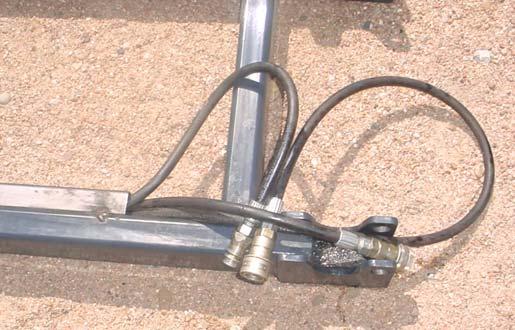
Pressure Hose with Female Quick Coupler
Power Beyond Hose with Male Quick Coupler
Return Hose with Female Quick Coupler

4.4.23. Before installing backhoe to tractor, use a hoist to install bucket on backhoe. Secure using 1" x 7.4" pins and 1/4" x 2-1/4" hardware.

Pin 1" x 7.4" and Hex Bolt 1/4"-20NC x 2-1/4" Grade 8, Lockwasher, and Hex Lock Nut, 2 places Bucket
4.4.24. Install backhoe to tractor as shown in section 9 Mounting Backhoe to Tractor.
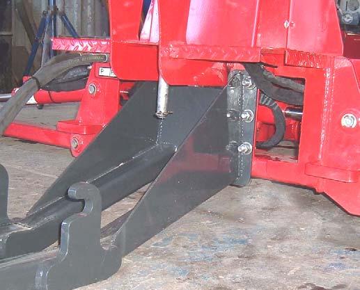
4.4.25. After backhoe is installed torque backhoe front mount bolts as specified in torque chart page 89.
Torque Backhoe Front Mount bolts as specified in torque chart
INSTALLATION INSTRUCTIONS FOR BACKHOE MODEL 1710C (2015/2216)
NOTE: Install backhoe hydraulic components to tractor hydraulic manifold block and loader valve as follows.
(*) IMPORTANT NOTE: Check your loader operator's manual for loader valve tank (OUT) port location. Loader valve tank (OUT) port location will vary depending on valve manufacturer.
LOADER RETURN TANK (OUT) PORT:
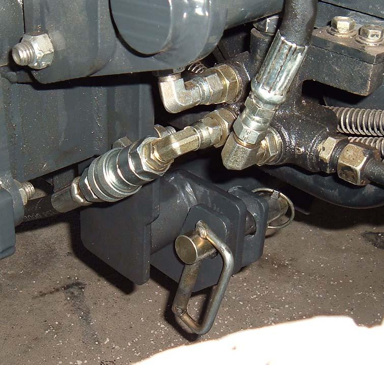
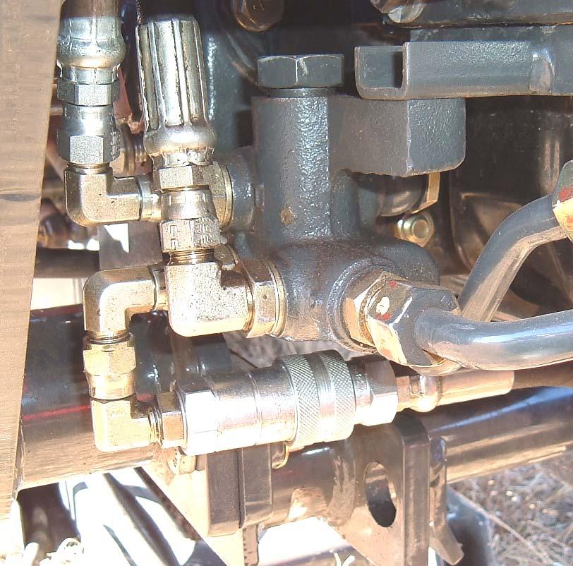
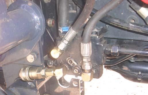
4.4.26. Remove existing loader tank (OUT) hose from loader valve and tractor hydraulic manifold block and discard.
4.4.27. Install Fitting Tee ORBM 3/4" x JICM 3/4" x JICM 3/4" to loader tank (OUT) port of valve (backhoe supplied).
4.4.28. Install Fitting 90o JICF 3/4" x JICM 3/4" and Hose 3/8" x 40" JICF 9/16" x JICF 3/4" to tee fitting run end (backhoe supplied).
4.4.29. Install Fitting Straight ORBM 3/4" x JICF 3/4" and Male Quick Coupler to tee fitting body end (backhoe supplied).
4.4.30. Connect other end of Hose 3/8" x 40" to existing 90o fitting in tractor hydraulic manifold block.
NOTE: 90o fitting supplied with loader must be used in tractor hydraulic manifold block.
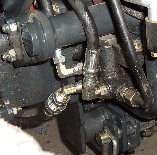
LOADER POWER BEYOND CIRCUIT:
4.4.31. Remove Loader Power Beyond "PB" Hose connected to tractor hydraulic manifold block.
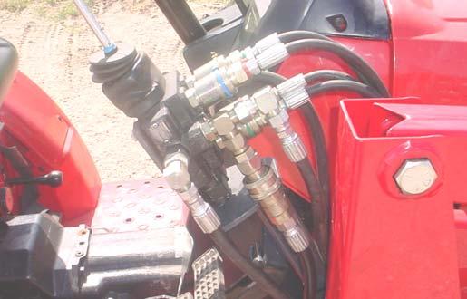
4.4.32. Install Fitting Straight JICF 9/16" x ORBM 3/4" and Female Quick Coupler to 90o fitting in power beyond port of hydraulic manifold block.
4.4.33. Install Fitting Straight JICF 9/16" x ORBM 3/4" and Male Quick Coupler (not shown) to open end of Loader Power Beyond "PB" Hose just removed.
4.4.34. Connect power beyond quick couplers together.
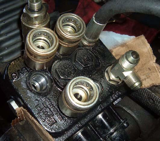
Fitting "T" ORBM 3/4" x JICM 3/4" x JICM 3/4"
Fitting 90o JICF 3/4" x JICM 3/4"
Female Quick Coupler (will be connected to Backhoe Power Beyond "PB" Hose marked with yellow tie)
Straight JICF 9/16" x ORBM 3/4"
"PB"
Manifold Block
Hydraulic Manifold Block
INSTALLATION INSTRUCTIONS FOR BACKHOE MODEL 1710C (2015/2216)
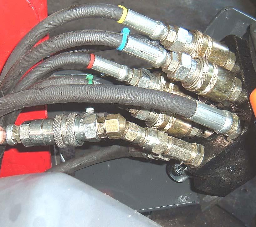
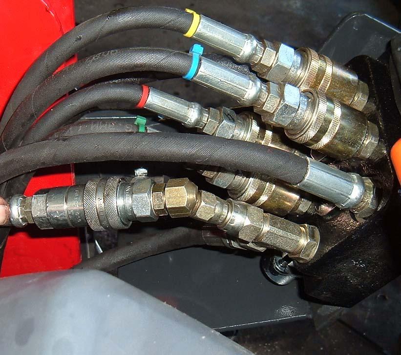
4.4.35. Install these 3 hoses to backhoe as shown.
4.4.36. Mark both ends of Pressure "P" Hose 3/8" x 67" ORBM 3/4" x JICF 3/4" using red nylon ties.
4.4.37. Mark both ends of Power Beyond "PB" Hose 3/8" x 82" ORBM 3/4" x JICF 3/4" using yellow nylon ties.
4.4.38. Mark both ends of Tank/Out "T" Hose 3/8" x 107" ORBM 3/4" x JICF 3/4" using green nylon ties.
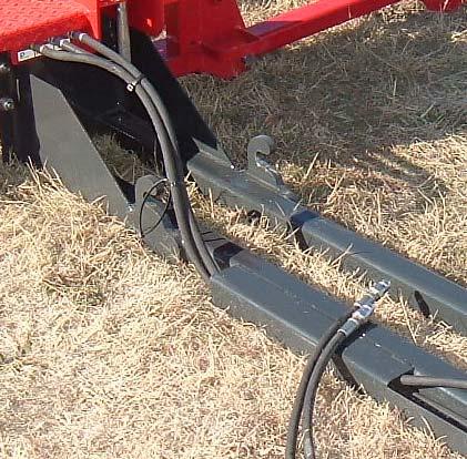
4.4.39. Route these 3 hoses through backhoe subframe channel.
Pressure "P" Hose. Power Beyond "PB" Hose. Tank/Out "T" Hose.
Backhoe Subframe Channel.
4.4.40. Install female quick coupler to Pressure "P" Hose 3/8" x 67" with red nylon ties. (Connects to Loader Power Beyond Hose.)
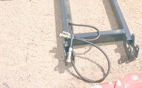
4.4.41. Install male quick coupler to Power Beyond "PB" Hose 3/8" x 82" with yellow nylon ties.
4.4.42. Install female quick coupler to Tank/Out "T" Hose 3/8" x 107" with green nylon ties.
4.4.43. Before installing backhoe to tractor, use a hoist to install bucket on backhoe. Secure using 1" x 7.4" pins and 1/4" x 2-1/4" hardware.
Pin 1" x 7.4" and Hex Bolt 1/4"-20NC x 2-1/4" Grade 8, Lockwasher, and Hex Lock Nut, 2 places Bucket
4.4.44. Install backhoe to tractor as shown in section 9 Mounting Backhoe to Tractor.
4.4.45. After backhoe is installed torque backhoe front mount bolts as specified in torque chart page 89.
Torque Backhoe Front Mount bolts as specified in torque chart
5. CONTROLS
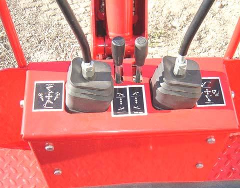
The backhoe has two single lever controls plus two stabilizer control levers, located on the console control panel directly ahead of the operator. Following is a list of the controls from left to right, with the function of each. NOTE: You will find some functions will not work when operating simultaneous operations. If this occurs, move lever to center and operate functions individually.
NOTE: You will hear some noise coming from the valve whenever a port relief opens. This noise is normal during backhoe operations.
5.1. Boom & Swing:
Push lever forward, boom moves down, away from operator.
Pull lever back, boom moves up, toward operator. The Boom/Swing Control Lever has an added “float” function. A detent or stop should be felt when the lever is pushed forward to move the boom down. Pushing the lever forward more will overcome the detent and cause the boom to float, or move down or up freely, depending on the forces acting on it. When the lever is released it should return to the center, neutral position.
Move lever to the left, backhoe swings to the left. Move lever to the right, backhoe swings to the right. By moving the lever to one of the intermediate positions, the boom can be swung left or right at the same time as the boom is being raised or lowered, performing two operations simultaneously.
Boom & Swing
Crowd & Bucket
SWING LEFT AND LOWER the boom by moving the control lever forward and to the left.
SWING LEFT AND RAISE the boom by moving the control lever back and to the left.
SWING RIGHT AND LOWER the boom by moving the control lever forward and to the right.
SWING RIGHT AND RAISE the boom by moving the control lever back and to the right.
5.2. Left Hand Stabilizer:
Push lever forward, the LH stabilizer lowers. Pull lever backward, the LH stabilizer raises.
5.3. Right Hand Stabilizer:
Push lever forward, the RH stabilizer lowers. Pull lever backward, the RH stabilizer raises.
5.4. Crowd & Bucket:
Push lever forward, the dipper assembly moves out, away from the operator. Pull lever back, the dipper assembly moves in, toward the operator. Move lever to the left, the bucket curls in. Move lever to the right, the bucket extends out.
By moving the lever to one of the intermediate positions, the dipper assembly can be extended or retracted at the same time as the bucket is being loaded or dumped, performing the two operations simultaneously.
EXTEND AND LOAD the bucket by moving the control lever forward and to the left.
RETRACT AND LOAD the bucket by moving the control lever back and to the left.
EXTEND AND DUMP the bucket by moving the control lever forward and to the right.
RETRACT AND DUMP the bucket by moving the control lever back and to the right.
The two operations of the boom control lever, combined with the two operations performed by the bucket and dipper control lever, provide four simultaneous operations from the two levers, keeping cycle time to a minimum. NOTE: You will find some functions will not work when operating simultaneous operations. If this occurs, move lever to center and operate functions individually. In general, the direction of movement of a control lever corresponds to the movement of the operating member.
5.5. Operating the Backhoe
CAUTION: Equip your tractor with a ROPS frame for your protection. See your tractor/ROPS Operator Manual for correct seat belt usage.
1. Disengage transport locking pins before attempting to operate the backhoe. Store transport locking pins in holes provided in operator platform.
2. Operate from the backhoe operator’s seat only.
3. Lower the stabilizers until the rear of the tractor is totally supported by them note: rear tires should not come up off of the ground.
4. Do not dig near the stabilizers.
5. Do not touch overhead wires with any part of the backhoe.
6. Do not attempt to raise the tractor off the ground or move the tractor forward or backward using the backhoe dipper assembly or bucket.
7. Do not lose stability by swinging the bucket downhill when positioned on a slope.
8. Do not lower the backhoe boom using the “float” function. It w ill freefall, and could result in serious injury to bystanders or damage to the backhoe.
It is not difficult to become an efficient operator. Control lever operating decals are located on the valve cover plate assembly. Study these decals. They will assist you in becoming familiar with the controls. Smooth, light handling of the controls will result in the most efficient backhoe operation.
Operate the backhoe control levers to become familiar with their speed and movements. The engine speed and the size of the hydraulic system will determine the speed of cylinder operation. When powering from tractor systems with higher output than required, reduce engine RPM to obtain acceptable backhoe operating speed. Swing the boom several times to practice controlling the speed of swing. Do not operate the swing more than 45 degrees each way for the first few times, then gradually increase the arc.
The boom “float” function may be used during digging to eliminate down pressure when cleaning the bottom of a trench. The primary purpose of the boom “float” function is to protect the operator from serious injury in the event that some component of the backhoe would fail.
Best results are obtained by digging near the center of the swing arc so material can be dumped on either side.
As the operator becomes more familiar with the operation of the backhoe, it will be common practice to operate two controls at one time. For example, with the bucket extended and the dipper assembly extended, the boom control and crowd control can be operated together to bring the bucket toward the operator with down pressure on it. As the dipper assembly approaches the operator, the crowd and bucket controls can be operated to close the bucket and trap the material. At the end of the stroke, the boom and crowd controls are operated to move the load up and away from the operator to save time in clearing the excavation.
This dual operation of controls will speed and simplify the digging operation. Normally the two or more movements will not be equal or even simultaneous, but as the pressure within the cylinders changes, and the resistance on an operating member of the hoe lessens, it will begin to move. It is balancing the force of one member against the other.
NOTE: Actuating the bucket is the key to powerful digging. Operating the crowd and bucket controls simultaneously will insure a full bucket and prevent waste motion and time.
NOTE: If any handle begins to develop excessive play, or becomes misaligned in neutral or center position, it is an indication that control handle or linkages have become loose or worn. Replace or repair immediately.