32 minute read
9. MOUNTING BACKHOE TO TRACTOR


MOUNTING INSTRUCTIONS FOR BACKHOE MODELS 1710A AND 1710B
CAUTION: Before leaving tractor seat, stop engine, lock brakes, relieve hydraulic pressure, and remove key.
CAUTION: Do not allow bystanders in area of backhoe when mounting, dismounting or when operating backhoe.
CAUTION: Do not stand, walk, or work under a raised backhoe component unless it is securely blocked or held in position. Accidental movement of valve handle/handles or leaks in the hydraulic system could cause backhoe component to drop, causing serious injury.
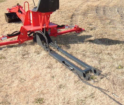
9.1. Position hoses forward so they can be connected to the tractor quick couplers and in a location where they will not be damaged as backhoe is mounted to tractor.
9.2. Center tractor on backhoe subframe.
NOTE: It is very important that the tractor is centered over the backhoe subframe to allow easy alignment and installation of the backhoe.
NOTE: Swing transport locking pin should be in the locked position during mounting.
NOTE: Remove Rear Ballast, 3 Point Top Link and Drawbar from tractor before installing Backhoe.
9.3. To aid in mounting and dismounting backhoe; apply a small amount of grease to backhoe subframe in areas of subframe hooks and subframe receivers.
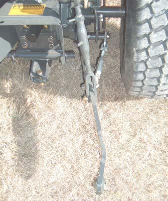
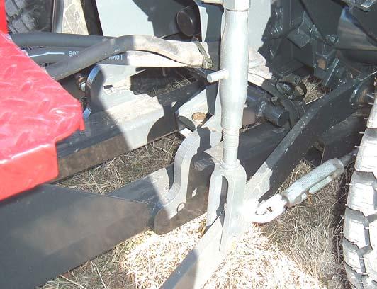
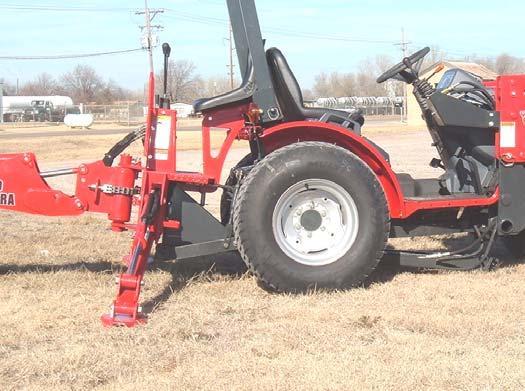
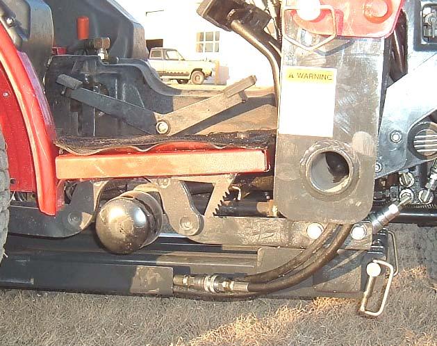
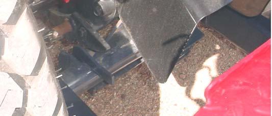
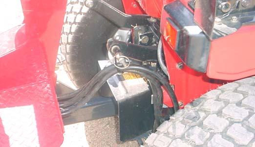
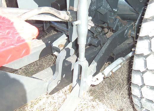
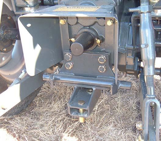
9.4. Before installation of backhoe onto your tractor adjust 3-point sway link so there is clearance between 3-point lower links and rear mount pins.
Rear Mount Pin
3-point Lower Link
Adjust 3-point sway link to prevent contact with backhoe rear bracket pin
CAUTION: Mount and dismount backhoe from tractor seat only. The only time it is permissible to operate backhoe controls from a position not within the backhoe operators area is during these operations.
NOTE: With backhoe parked operator may want to remove backhoe rear bracket so no interference between 3-point lower link and this bracket occurs. Check clearance of your 3-point application before operation.
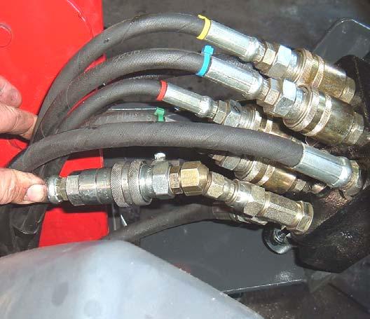
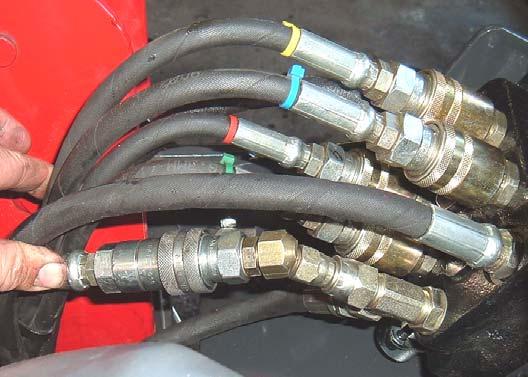
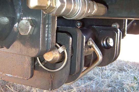
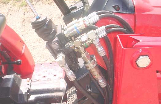
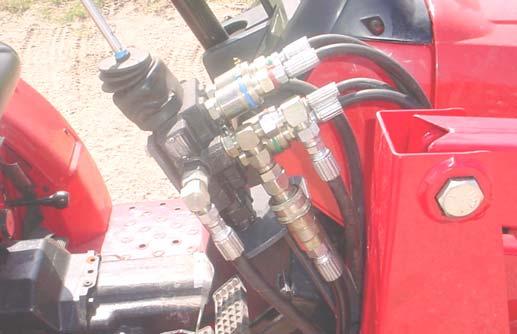
Disconnect
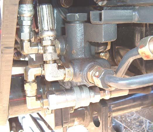
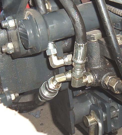
9.8. BACKHOE TANK/OUT "T": (1710A –1815/1816)
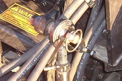
Connect Female Quick Coupler on Backhoe Tank/Out "T" Hose 3/8" x 112" with green nylon tie to Male Quick Coupler on Loader Valve "OUT" Port Tee Fitting.
Female Quick Coupler on "T" Hose
IMPORTANT: To avoid hydraulic hose damage, be alert and make sure hoses are not stretched, caught, or pinched during mounting and dismounting of backhoe.
IMPORTANT: After installation check that tractor brake pedal components clear all loader and backhoe components. If contact occurs see tractor manual and adjust brake travel to eliminate contact.
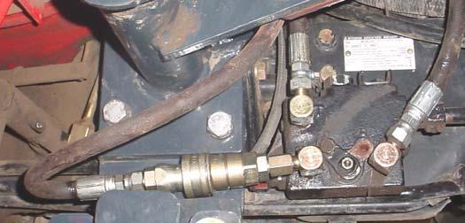
9.9.
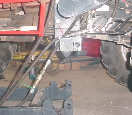
POWER BEYOND "PB": (1710B –2415/2516)
Disconnect loader power beyond couplers. Connect male quick coupler on Backhoe Power Beyond "PB" 3/8" x 93" Hose marked with yellow nylon tie to female quick coupler on tractor manifold block.
Male Quick Coupler installed on Backhoe Power Beyond Hose
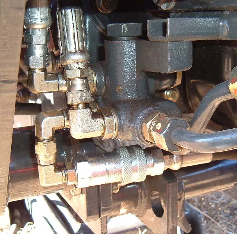
9.10.
PRESSURE "P": (1710B –2415/2516)
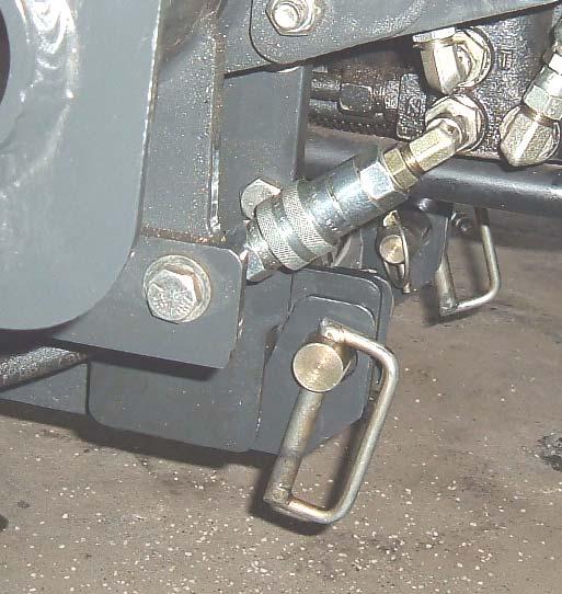
Connect female quick coupler on Backhoe Pressure "P" 3/8" x 57" Hose marked with red nylon tie to male quick coupler on loader power beyond hose.
Female Quick Coupler installed on Backhoe Pressure Hose
Male Quick Coupler installed on Loader Power Beyond Hose
9.11. BACKHOE TANK/OUT "T": (1710B)
Connect Female Quick Coupler on Backhoe Tank/Out "T" Hose 3/8" x 112" with green nylon tie to Male Quick Coupler on Loader Valve "OUT" Port Tee Fitting.
Female Quick Coupler on "T" Hose
IMPORTANT: To avoid hydraulic hose damage, be alert and make sure hoses are not stretched, caught, or pinched during mounting and dismounting of backhoe.
IMPORTANT: After installation check that tractor brake pedal components clear all loader and backhoe components. If contact occurs see tractor manual and adjust brake travel to eliminate contact.

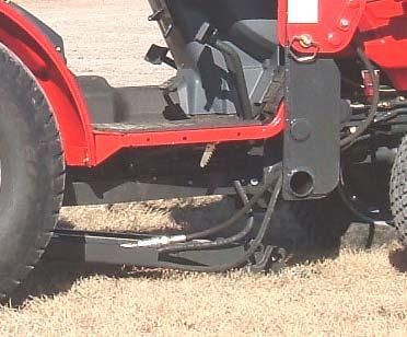
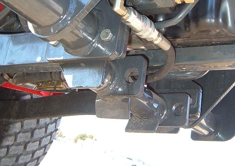
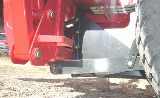
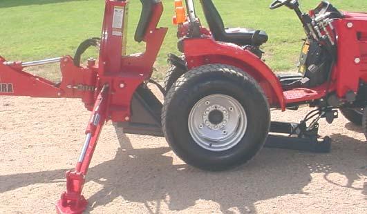
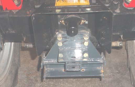
9.12. Lower tractor 3-point arms. To improve operator view, backhoe seat can be tilted toward backhoe.Back tractor until the backhoe subframe hooks are directly below and behind rear mount pins.
Rear Mount Pins
Backhoe Subframe Hooks
CAUTION: Operator must keep hands and body out of the area between the backhoe and tractor when mounting and dismounting the backhoe. Failure to follow these instructions could result in serious injury.
Lower
9.1.2. Adjust stabilizer cylinders until backhoe subframe hooks are aligned with and are parallel to rear mount pins.

Backhoe Subframe Hooks positioned upward (not shown in photo)
Backhoe Subframe Receivers positioned low
NOTE: Extend boom cylinder to keep backhoe subframe receivers low
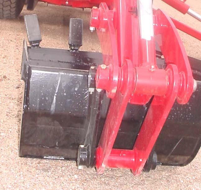
9.1. Back tractor until backhoe subframe hooks are positioned on rear mount pins.
Backhoe Subframe Hooks positioned on Rear Backhoe Mount Pins
Rear Backhoe Mount Pins
IMPORTANT: To avoid hydraulic hose damage, be alert and make sure hoses are not stretched, caught, or pinched during mounting and dismounting of backhoe.
9.2. Adjust backhoe boom and stabilizer cylinders until backhoe subframe receiver rotates upward and engages backhoe center bracket crosspipe.
Boom Cylinder retracted slightly
Stabilizer Cylinders retracted slightly
Backhoe Subframe Receivers engaged into Backhoe Center Bracket Crosspipe
NOTE: It is critical that backhoe subframe is centered under tractor to allow subframe to engage correctly.
Subframe centered under Tractor and engaged in Backhoe Front Mount Bracket Crosstube
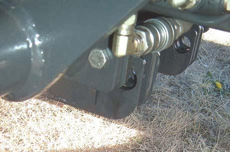
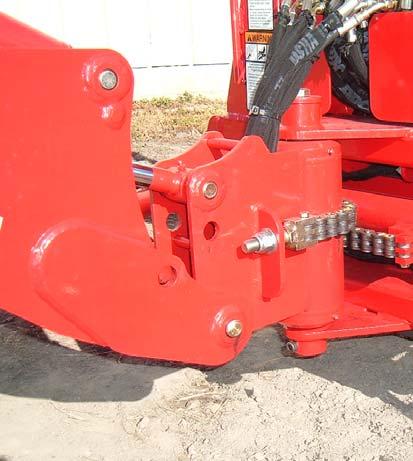
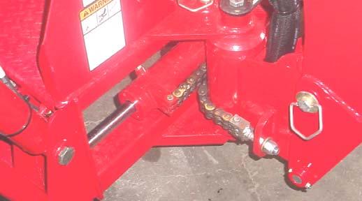
9.3. Shut off tractor. Secure backhoe subframe receivers to backhoe center bracket crosspipe by installing quick pin into receiver hole (see photo below) and securing it with a snap pin, 1 place each side. (1710A Quick Pin direction shown in photo)

Backhoe Subframe Receiver Quick Pin and Snap Pin 1 place each side, install into Receiver Hole
Receiver Hole for Quick Pin
Backhoe Center Bracket Crosspipe
9.4. Shut off tractor. Secure backhoe subframe receivers to backhoe center bracket crosspipe by installing quick pin into receiver hole (see photo below) in the direction shown, and securing it with a snap pin, 1 place each side. (1710B Quick pin direction shown in photo)
Backhoe Subframe Receiver
Quick Pin and Snap Pin 1 place each side, install into Receiver Hole
Receiver Hole for Quick Pin
Backhoe Center Bracket Crosspipe
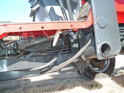
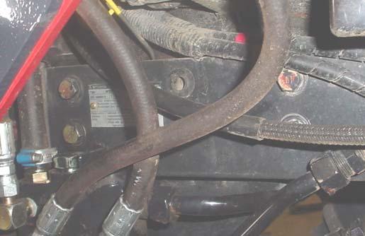
9.5. After backhoe is installed on tractor check that tractor brake pedal components clear all loader and backhoe components. If contact occurs see tractor manual and adjust brake travel to eliminate contact.
Check that all hoses clear all tractor brake components
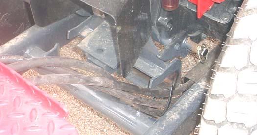
9.6. After installation route hoses inside subframe hose channel. Subframe Hose Channel
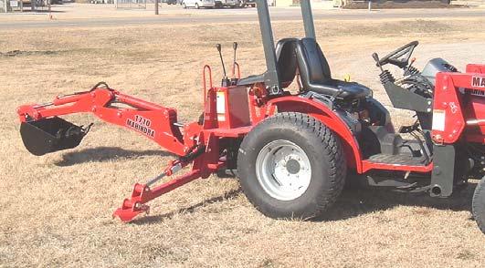
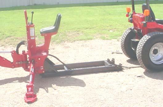
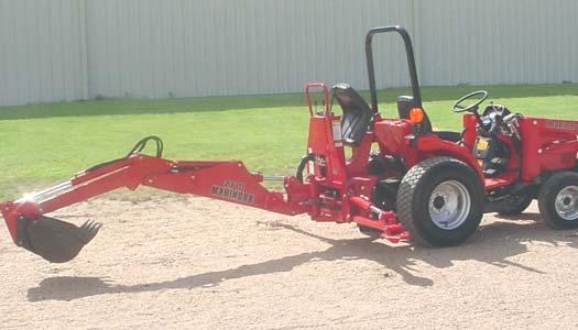
9.7. Position backhoe in transport position and install transport locking pins. Refer to Page 45-46.
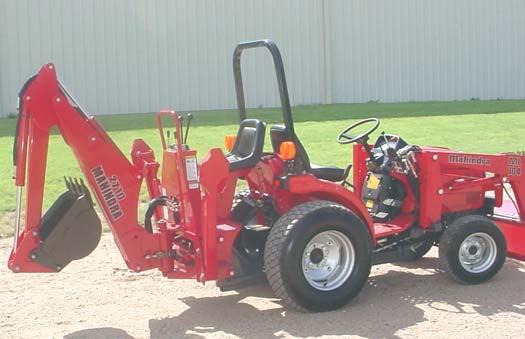
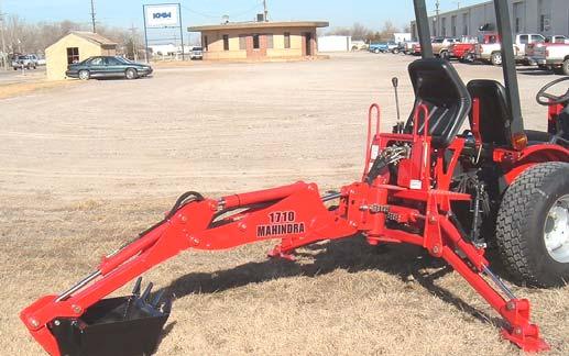
9.8. Backhoe shown in transport position with transport locking pins secured.
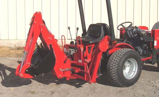
NOTE: Slight positioning of boom and stabilizer cylinders may be required to allow easy installation of these transport locking pins.
9.9. 1710A and 1710B only use tractor 3-point lever to raise 3-point lower links so they just clear backhoe frame. Do not allow these links to contact frame or damage to backhoe frame and hydraulic system could occur.
Raise 3-point Lower Links so they just clear Backhoe Frame
NOTE: Do not allow 3-Point Lower Links to contact any components on backhoe. Failure to follow these instructions can cause damage to backhoe, 3-Point Lower Links or Hydraulic System not covered under warranty.
9.10. 1710A and 1710 B use only with 3-point lower link in position lock 3-point control handle in position using both 3-point handle locks located on tractor.
Position and secure Handle Raise Lock
3-point Control Handle
Position and secure Handle Lower Lock
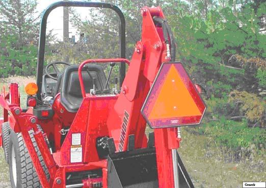
9.11. If unit will be operated on roads, always secure a slow moving vehicle (SMV) sign to backhoe bucket cylinder or dipper assembly using appropriate means. Remove sign when digging.
Slow Moving Vehicle (SMV) Sign
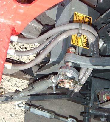
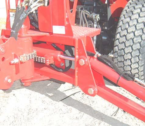
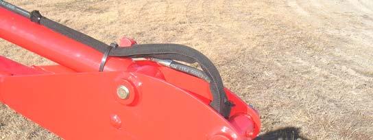
9.12. Pull the 3 backhoe hydraulic hoses rearward toward the backhoe and secure them to the 3-point top link using nylon ties as shown. Leave tie slightly loose so it can be easily removed when dismounting the backhoe. Make sure all hoses are secured to prevent damage during operation of the backhoe.
Nylon Ties
Position hoses so they will not be damaged
Secure three Backhoe Hydraulic Hoses with one Nylon Tie as shown
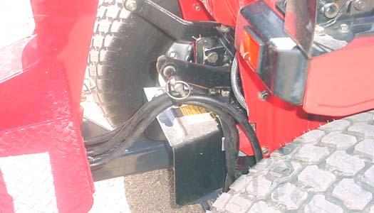
Wrap one Nylon Tie through Nylon Tie securing three Backhoe Hydraulic Hoses together and around 3-Point link as shown
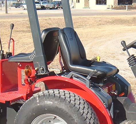

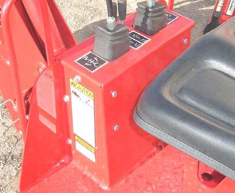
9.13. Before backhoe operation slide tractor seat forward so there is at least 1” of clearance between tractor seat and backhoe seat.
Adjust Tractor Seat forward so there is at least 1” of clearance between seats
Remove Slow Moving Vehicle Sign Bracket
10. MOUNTING BACKHOE TO TRACTOR
MOUNTING INSTRUCTIONS FOR BACKHOE MODEL 1710C (2015/2216):
CAUTION: Before leaving tractor seat, stop engine, lock brakes, relieve hydraulic pressure, and remove key.
CAUTION: Do not allow bystanders in area of backhoe when mounting, dismounting or when operating backhoe.
CAUTION: Do not stand, walk, or work under a raised backhoe component unless it is securely blocked or held in position. Accidental movement of valve handle/handles or leaks in the hydraulic system could cause backhoe component to drop, causing serious injury.
ALL MODELS:
10.1. Position hoses forward so they can be connected to the tractor quick couplers and in a location where they will not be damaged as backhoe is mounted to tractor.
10.2. Center tractor on backhoe subframe.
NOTE: It is very important that the tractor is centered over the backhoe subframe to allow easy alignment and installation of the backhoe.

NOTE: Swing transport locking pin should be in the locked position during mounting.
MODELS 1710C:
10.3. To aid in mounting and dismounting backhoe; apply a small amount of grease to backhoe subframe in areas of (A) subframe crosspipe and (B) subframe receivers.
(A) 1710C: Subframe Crosspipes
CAUTION: Mount and dismount backhoe from tractor seat only. The only time it is permissible to operate backhoe controls from a position not within the backhoe operators area is during these operations.
ALL MODELS:
10.4. Rotate backhoe seat toward backhoe.
10.5. Back tractor over top of backhoe subframe until backhoe hoses can be connected to tractor hydraulic quick couplers. Shut off tractor engine. Connect backhoe hydraulics as follows.
MODEL 1710C (2015/2216):
10.6. BACKHOE POWER BEYOND "PB":
Disconnect loader power beyond couplers. Connect male quick coupler on Backhoe Power Beyond "PB" 3/8" x 82" Hose marked with yellow nylon tie to female quick coupler on tractor manifold block.
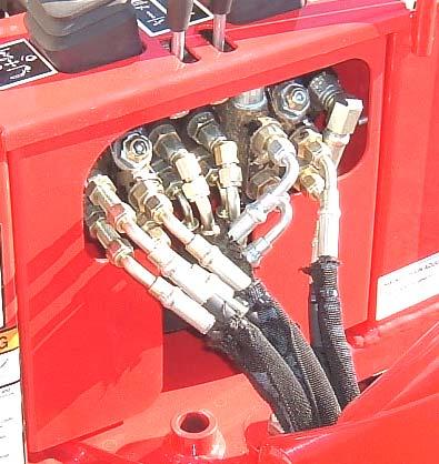
Tank/Out "T" Hose 3/8" x 107" ORBM 3/4" x JICF 3/4" marked with green nylon tie connected to Loader Valve.
Female Quick Coupler installed to Tractor Manifold Block.
Male Quick Coupler installed to Power Beyond "PB" Hose.
Power Beyond "PB" Hose 3/8" x 82" ORBM 3/4" x JICF 3/4" marked with yellow nylon tie.
10.7. BACKHOE PRESSURE "P":
Connect female quick coupler on Backhoe Pressure "P" 3/8" x 67" Hose marked with red nylon tie to male quick coupler on loader power beyond hose.
Male Quick Coupler installed to Loader Power Beyond Hose.
Female Quick Coupler installed to Pressure "P" Hose.
Pressure "P" Hose 3/8" x 67" marked with red nylon tie.
10.8. BACKHOE TANK/OUT "T":
Connect Female Quick Coupler on Backhoe Tank/Out "T" Hose 3/8" x 107" with green nylon tie to Male Quick Coupler on Loader Valve "OUT" Port Tee Fitting.
Male Quick Coupler on "T" Hose.
Female Quick Coupler on "T" Hose.
Tank/Out "T" Hose 3/8" x 107" ORBM 3/4" x JICF 3/4" with green nylon tie.
IMPORTANT: To avoid hydraulic hose damage, be alert and make sure hoses are not stretched, caught, or pinched during mounting and dismounting of backhoe.
MODEL 1710C (2015/2216):
10.9. With backhoe seat tilted toward backhoe, back tractor until the backhoe subframe crosspipe is directly below and behind backhoe rear bracket channel.
10.10. Keep backhoe subframe receivers low by extending boom cylinder.
Backhoe Rear Bracket.
Backhoe Subframe Crosspipe. Backhoe Rear Bracket Channel.
Power Pressure Beyond “PB” “P” Port
Port for Hose for Hose
To Backhoe. To Loader
Tank “OUT” Valve.
Port for Hose To Loader Valve.
MODEL 1710C (2015/2216):
10.11. With backhoe seat tilted toward backhoe, extend stabilizer cylinders to lift backhoe subframe crosspipe up to backhoe rear bracket channel. Adjust stabilizer cylinders until backhoe subframe crosspipe is aligned with and is parallel to backhoe rear bracket channel.
Backhoe Subframe Crosspipe positioned upward.
Backhoe Subframe Receivers positioned low.
NOTE: Extend boom cylinder to keep backhoe subframe receivers low.
MODELS 1710C (2015/2216):
10.12. Back tractor until backhoe subframe crosspipe is positioned into backhoe rear bracket channel.
Backhoe Subframe Crosspipe positioned into Backhoe Rear Bracket Channel.
10.13. Adjust backhoe boom and stabilizer cylinders until backhoe subframe receivers rotate upward and engage backhoe center bracket crosspipe.
Boom Cylinder retracted slightly.
Stabilizer Cylinders retracted slightly.
Backhoe Subframe Receivers engaged into Backhoe Center Bracket Crosspipe.
10.14. Shut off tractor. Secure backhoe subframe receivers to backhoe center bracket crosspipe by installing quick pin into receiver hole and securing it with a snap pin, 1 place each side.

Backhoe Subframe Receiver. Backhoe Center Bracket Crosspipe.
Receiver Hole for Quick Pin. Quick Pin and Snap Pin 1 place each side, install into Receiver Hole.
NOTE: Model 1710C (2015/2216):Slight positioning of boom and stabilizer cylinders may be required to allow easy installation of these quick pins.
10.15. Position backhoe in transport position and install transport locking pins. Refer to Page 45-46. 10.16. Backhoe shown in transport position with transport locking pins secured.
10.17. If unit will be operated on roads, always secure a slow moving vehicle (SMV) sign to backhoe bucket cylinder or dipper assembly using appropriate means. Remove sign when digging.
Slow Moving Vehicle (SMV) Sign.
10.18. Pull the 3 backhoe hydraulic hoses rearward toward the backhoe and secure them to the 3-point top link using nylon tie as shown. Leave tie slightly loose so it can be easily removed when dismounting the backhoe. Make sure all hoses are secured to prevent damage during operation of the backhoe.
Nylon Tie. Position hoses so they will not be damaged.
11. INITIAL BACKHOE OPERATION
11.1. Check the tractor hydraulic oil level and fill if required
11.2. Set tractor engine at a low idle during initial backhoe operation.
11.3. Operate stabilizer cylinders a number of times, fully up and fully down.
11.4. Operate all the functions of the backhoe until all air has been purged from the system.
11.5. Recheck the tractor hydraulic oil level and fill as required.
11.6. Check that swing chain is properly adjusted.
12. DISMOUNTING BACKHOE FROM TRACTOR 1710A (1815/1816) and 1710B (2415/2516)
CAUTION: Before leaving the tractor seat, stop engine, lock brakes, relieve hydraulic pressure, and remove key.
CAUTION: Do not stand, walk, or work under a raised backhoe unless it is securely blocked or held in position. Accidental movement of valve handle/handles or leaks in the hydraulic system could cause the backhoe to drop, causing serious injury.
CAUTION: Do not allow bystanders in loader work area.
12.1. Position the tractor on a hard level surface. The more level the surface the easier the backhoe is to mount and dismount.
12.2. Remove boom transport locking pin and return to storage position. Refer to Page 46.
NOTE: Swing transport locking pin should remain in the locked position.
12.3. Extend boom cylinder to position bucket on ground.
12.4. Extend stabilizer cylinders so stabilizers rest on ground.
12.5. Remove nylon tie securing hoses to 3-point link at rear area of backhoe and pull hoses so hose slack is towards backhoe center bracket.
12.6. Remove the two quick pins and snap pins securing backhoe subframe receivers to backhoe center bracket crosspipe.
Quick Pins and Snap Pins Removed
NOTE: Slight positioning of stabilizers and boom assembly may be required to allow easy removal of these quick pins.
CAUTION: Mount and dismount backhoe from tractor seat only. The only time it is permissible to operate backhoe controls from a position not within the backhoe operators area is during these operations.
CAUTION: Operator must keep hands and body out of the area between the backhoe and tractor when mounting and dismounting the backhoe. Failure to follow these instructions could result in serious injury.
12.7. Rotating backhoe seat toward backhoe will improve operator visibility. Lower stabilizers. Adjust boom and stabilizer cylinders so that backhoe subframe receivers are disengaged and lowered from the backhoe center bracket crosspipe and the backhoe subframe hooks are free from rear mount pins.
12.8. Drive tractor slightly forward until backhoe subframe hooks disengage from rear mount pins.
IMPORTANT: To avoid hydraulic hose damage, be alert and make sure hoses are not stretched, caught, or pinched during mounting and dismounting of backhoe.
Backhoe Rear Mount Pins
Backhoe Subframe Hooks
12.9. Using boom and stabilizer cylinders, position backhoe so it rests on the ground.
12.10. Relieve all pressure in all circuits by shutting of the tractor and working all backhoe control levers in all directions.

12.11. 1710A (1815/1816) Disconnect the three backhoe hydraulic quick couplers at the center of the tractor and then connect male quick coupler on the 3/8” x 47” hose assembly installed in the power beyond “BYD” port of the loader valve to the female quick coupler installed in the power beyond “N” port of the tractor hydraulic block.
3/8” x 47” Loader Power Beyond hose
Beyond
NOTE: Route Hydraulic Hoses so they do not contact any brake components.
12.12. 1710B (2415/2516) Disconnect the three backhoe hydraulic quick couplers at the center of the tractor and then connect male quick coupler on the 3/8” x 65” hose assembly installed in the power beyond “BYD” port of the loader valve to the female quick coupler installed in the power beyond “N” port of the tractor hydraulic block.
3/8” x 65” Loader Power Beyond hose
Model
12.13. 1710C (2015/2216): Disconnect the three backhoe hydraulic quick couplers at the center of the tractor and then drive forward.
Male Quick Coupler from Backhoe Tank "T" Hose.
Female Quick Coupler mounted on Tractor Hydraulic Manifold Block. (*)
12.14. 1710C (2015/2216): Connect male quick coupler from loader power beyond "PB" hose to female quick coupler mounted to tractor hydraulic manifold block. This step must be done to complete the loader circuit when backhoe is dismounted from the tractor.

(*)NOTE: When backhoe is not attached, connect Loader Power Beyond "PB" Male Quick Coupler to Female Quick Coupler mounted to Tractor Hydraulic Manifold Block to complete loader circuit.
12.15. 1710C (2015/2216): Disconnect female quick coupler on backhoe tank/out "T" hose 3/8" x 107" marked with green nylon tie.
Female Quick Coupler on Backhoe Tank/Out "T" Hose 3/8" x 107" marked with green nylon tie.
12.16. 1710A, 1710B, and 1710C : Reinstall the following equipment on tractor: Belly mower (if so equipped).

Loader Rear Ballast. Drawbar.
Slow Moving Vehicle Sign.
3-Point upper link.
Replace Slow Moving Vehicle Sign, 3-Point Upper Link, Drawbar,
CAUTION: If using tractor for loader use, original rear ballast MUST be reinstalled on tractor for safety and stability.
13.1. Service Safety
CAUTION: To avoid possible injury, observe the following safety rules WHEN SERVICING the backhoe.
13.1.1. Engage transport locking pins before servicing the backhoe. Refer to Page 45-46.
13.1.2. Do not oil, grease, or adjust the backhoe while it is in motion.
13.1.3. Do not change any backhoe relief valve settings. They are factory set for best performance and safety.
13.1.4. Protect your eyes - wear safety glasses. Guard against injury when driving connecting pins or performing any repair in which particles can chip from work piece or striking tool.
13.2. Hydraulic Fluid
13.2.1. With the engine off and the backhoe on the ground, inspect all hoses for cuts or wear. Check for signs of leaks and make sure all fittings are tight.
CAUTION: Escaping hydraulic fluid under pressure can have sufficient force to penetrate skin, causing serious personal injury. Before disconnecting lines, be sure to relieve all pressure.
Before applying pressure to system, be sure all connections are tight and that lines, tubes, and hoses are not damaged. Fluid escaping from a very small hole can be almost invisible. Use a piece of cardboard or wood, rather than hands, to search for suspected leaks.
If injured by escaping fluid, see a doctor at once. Serious infection or reaction can develop if proper medical treatment is not administered immediately.
13.3.
Beginning Of Season
13.3.1. Remove all protective covering.
13.3.2. Check hydraulic hoses for deterioration and replace, if necessary.
13.3.3. Lubricate all grease fittings and oil handle linkages.
13.3.4. Check hydraulic system for loss of fluid and, if necessary, fill to proper level.
13.3.5. Tighten all loose bolts, nuts and set screws.
13.3.6. Inspect bucket teeth and, if necessary, replace them.
13.3.7. Operate the backhoe slowly for a short time before placing the unit under full load.
13.3.8. Check to make sure Swing Chain is adjusted correctly. See pages 77 through 78.
13.4. Bleeding Backhoe Hydraulic System
13.4.1. If the hydraulic hoses have been disconnected from the backhoe or tractor, all trapped air must be removed after the hoses are connected. Start tractor engine and operate backhoe through all movements fully, several times, to purge the system of air.
13.5. Hydraulic System Hoses
13.5.1. Oil leaks in the pressure side of the system can be located by carefully inspecting the external area of the hoses and fittings.
13.5.2. When tightening connections, always use two wrenches.
IMPORTANT: Do not over-tighten fittings. Make them tight enough to eliminate leaks.
13.5.3. Hoses on any backhoe are very severely worked and will fail in time. Examine them regularly and replace any that show signs of failure. Pay careful attention to the routing of hoses so they can move fully and freely without kinking, and cannot be pinched or cut by any part of the backhoe.
13.6. Weld On Tooth Replacement
13.6.1. The bucket tooth points are self-sharpening and will require little attention; however, these points on the bucket shanks can be replaced when they become badly worn or broken.
13.6.2. A tooth point can be removed from the welded tooth shank by hammering at “A” on the tooth point or by driving a chisel at “B”, just between the tooth point box section and the tooth shank. Install the new point and anchor it to the shank by peening at the location shown.
13.6.3. If a tooth shank breaks off, becomes damaged, or lost so that it cannot hold a tooth point, a new shank should be welded to the bucket in its place.
All Models
13.7. Tightening Nuts and Bolts
13.7.1. Check all hardware on backhoe and tractor engine bolts daily before operation. Tighten hardware as specified. See Torque Chart, Page 89.
13.8. Check Tractor Side Rails Hardware
13.8.1. 1710C (2015/2216) These bolts should have been removed cleaned, "Loctited", torqued and marked during backhoe installation. If this was done, operator can simply check that all bolts have remained on their marks. If any of these bolts have moved off their marks, they must be removed cleaned, "Loctited", torqued and remarked before operating unit.
13.9. Check Backhoe Rear Bracket Hardware
13.9.1. 1710C (2015/2216) These bolts should have been removed cleaned, "Loctited", torqued and marked during backhoe installation. If this was done, operator can simply check that all bolts have remained on their marks. If any of these bolts have moved off their marks, they must be removed cleaned, "Loctited", torqued and remarked before operating unit.
IMPORTANT: These bolts must remain tight during operation to prevent damage to your tractor.
13.10. Check Backhoe Rear Mount Hardware
13.10.1. Check rear mount hardware torque at regular intervals. If any loosening of these bolts occurs tighten to specification. See torque specifications on page 22 for 1710A (1815/1816), page 24 for 1710B (2415/2516), and page 26 for 1710C. (2015/2216).
IMPORTANT: These bolts must remain tight during operation to prevent damage to your tractor.
13.11. Check Pivot Pins
13.11.1. Check all backhoe pivot pins for bolts, washers, and nuts, if missing or damaged, replace.
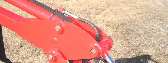
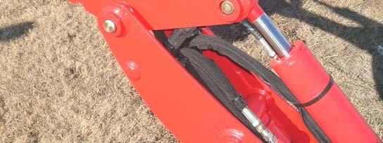
13.11.2. To reduce hose wear check that hose wrap covers complete hose and that hose wrap is secure to hose on each end. If hose wrap has moved readjust and secure.
Check Hose Wrap periodically and readjust and secure both ends if necessary
13.12. Lubrication
13.12.1. Economical and efficient operation of the backhoe is dependent upon regular and proper lubrication of all moving parts with a quality lubricant. Using high quality grease when servicing unit will result in less wear.
IMPORTANT: Avoid excessive greasing. Dirt collects on exposed grease and increases wear greatly. Clean all fittings thoroughly before using grease gun. After greasing, wipe off excessive grease from fittings.
13.12.2. Lower stabilizers to the ground, extend dipper and bucket cylinders, and lower boom assembly so bucket rests on the ground as shown.

13.12.3. Refer to photo below and photos on the next page for the location of all grease fittings.
13.12.4. Lubricate parts provided with grease fittings and all pivots during initial setup and then at least twice daily, once at the beginning of operation and again approximately halfway through the work day or after every 5 hours of operation or as indicated.
13.12.5. If any grease fittings are missing, replace them immediately.
Swing Grease Zerks are Located on Side of Swing Assembly. One on Top and One on Bottom of Swing Assembly
Boom Pivot Grease Zerk is located on Bottom Side of This Bushing

Front Side of Dipper Assembly. Lubricate Bucket Pivots and Linkages every 5 Hours of Operation
Stabilizer Pivot Grease Zerks, 4 places each side. See General Lubrication Photo for Stabilizer Opposite End Grease Zerk Locations
13.13. Swing Pivot Service
13.13.1. The Swing Assembly King Pin Retaining Bolt was cleaned, Shimmed, "Loctited" and torqued to 150 ft. lb. at the Factory.
13.13.2. If servicing swing bearings, always clean, "Loctite", and reassemble using King Pin Retaining Bolt, .075” Shim and Special Washer as shown, torque to 150 ft. lb.
King Pin Retaining Bolt Special Washer
13.14. Valve And Handle Linkage Service
13.14.1. Inspect console valve, handle linkage, and hoses after every 6 months of operation.
13.14.2. Remove 4 bolts from each side of console control panel and remove 2 bolts from each side of valve cover plate assembly, then remove console cover and valve cover plate assembly. Backhoe valve, handle components, and hoses will be exposed.
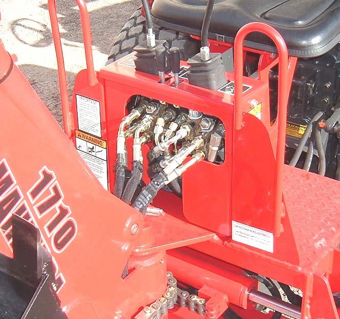
13.14.3. Clean and inspect all components for damage, replace as required. Lubricate all handle components with a high grade of spray lubricant.
Valve Cover Plate Assembly
Console Cover
13.14.4. Replace front cover and secure using Hex Bolt 1/4"-20NC x 1" Grade 5, Lockwasher, and Flatwasher, 2 places each side. Replace valve cover plate assembly and secure using Hex Bolt 1/4"-20NC x 1" Grade 5, Lockwasher, and Flatwasher, 1 place each side.
Hex Bolt 1/4"-20NC x 1" Grade 5, Lockwasher, and Flatwasher, 2 places each side
Hex Bolt 1/4"-20NC x 1" Grade 5, Lockwasher, and Flatwasher, 1 place each side
13.14.5. If valve handle is loose check to make sure mounting hardware is secure. Replace any worn or damaged control handle parts.
Check to make sure all mounting hardware is secure
Swing Chain Service
13.14.6. Lubricate the chain when it appears to be dry. Use a high grade of chain lubricant when servicing.
13.15. Swing Chain Adjustment and Service Instructions
13.15.1. When you first receive backhoe, and periodically thereafter, it will be necessary to adjust the swing chains. Keeping swing chains in proper adjustment will allow backhoe to swing the same distance from right and left and will keep from voiding warranty.
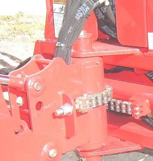
13.15.2. Secure swing cylinder by installing swing transport locking pin. Adjust swing chain by loosening or tightened 3/4" locknut until measurements from the cylinder tube end and the backhoe end plate are the same from right hand and left hand sides. This will allow backhoe to swing the same distance right and left.
Backhoe End Plate
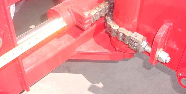
Measurements for RH and LH sides must be the same
Position Bolt Head Upward in Upper Chain, 2 places. Torque to 54 ft. lbs. max.
Chain Bolt
Flatwasher 3/4" Hardened
Hex Nut 3/4"10NC Nylon Lock
Position Bolt Head Downward in Lower Chain, 2 place

Cylinder Tube End
IMPORTANT: If chain becomes loose during operation, immediately adjust as described and tighten nylon locknut to equalize swing travel.
Swing Chain Adjustment and Service Instructions
NOTE A: Swing chain adjustment and service is critical to trouble free operation of your backhoe. Adjust swing chains as specified in 14.12.2. instructions in this manual then cycle backhoe swing fully right, inspect Point A and Point B components to make sure no contact exists, then repeat with backhoe swung fully left. If contact either direction is found readjust swing chains and reinspect specified areas.
Point A: If swing chains are adjusted properly there will be no contact between chain adjustment lug and cylinder lug. If contact exists adjust swing chains.
Point B: If swing chains are adjusted properly there will be no contact between cylinder lug and swing frame tube. If contact exists adjust swing chain.
Attaching Lug
Cylinder
Cylinder Lug
NOTE B: After every 50 hours of backhoe operation, replace the hardware that secures the swing chains to the cylinder. Use only factory approved 3/8”-16NC x 1-3/4” Grade 8 bolts, torque these bolts to a max. of 54 ft. lbs. of torque.
Replace 3/8”-16NC x 1-3/4” grade 8 bolts every 50 hours of backhoe operation, 2 places
IMPORTANT: Failure to follow NOTE: A and B instructions could result in cylinder damage caused by chain attaching bolts shearing because of normal wear of this bolt or backhoe components contacting each other during operation, failures in this area caused by incorrect swing chain adjustment or servicing of attaching bolts are not covered under warranty.
13.16. Swing Chain Replacement
13.16.1. Secure swing cylinder by installing swing transport locking pin. Remove nuts, flatwashers, chain bolts, hex bolts, and chains from backhoe. Lay new swing chains into position and secure to swing cylinder and chain bolts using new Hex Head Cap Screw 3/8”-16NC x 1-3/4" Grade 8, 2 places in each chain. Secure chain bolt using new Flatwasher 3/4" Hardened and Hex Nut 3/4"-10NC Nylon Lock, 1 place each side.
NOTE: Bolt heads must be positioned downward in lower chain and upward in upper chain as shown above to prevent damage to bolts or other backhoe components.

13.17. Bucket Cylinder Hose Routing
13.17.1. During initial operation make sure bucket hoses are rotated correctly by operating backhoe dipper circuit. Bucket hoses should position with hose loop as shown in Fig. 1. If hoses are positioned as shown in Fig. 2, do not operate bucket. Route hoses so they will loop as shown in Fig. 1.
Correct hose routing
Incorrect hose routing

13.18. Replacing Swing Cylinder Tube Assembly
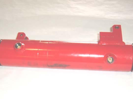
NOTE: Replace Swing Tube as follows:

13.18.1. Relieve all oil pressure in system. Refer to your Backhoe operator’s manual and review all safety items. Clean swing cylinder and port connections. Disconnect hydraulic hoses from your swing cylinder.
13.18.2. Remove Swing Cylinder from your Backhoe by removing the two mounting bolts. Remove fittings from your swing cylinder making sure you remove the orifice plates that are located in each port. Orifice plates are screw-in type.
Remove Orifice Plates
13.18.3. Loosen both swing cylinder head assemblies use an expander wrench or a small punch and hammer. If using a punch and hammer to loosen take care not to damage head assembly.
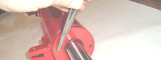
13.18.4. Clean all parts thoroughly. Inspect all components before reassembly. Lubricate inside of new Tube Assembly and seals prior to installation with hydraulic oil. Remove one cylinder head assembly from the damaged tube assembly and install it in the new tube assembly. Loctite 242 should be applied to threads on heads (none allowed on first thread). Apply two dots of loctite 180° apart.
New Head Assembly installed in new Tube Assembly
13.18.5. Carefully slide piston rod assembly out of the damaged tube assembly. You may have to lightly tap on this assembly to remove it. If so install a bolt in the end of the rod and tap on the head of the bolt.
Bolt installed in Rod End
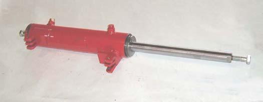
13.18.6. Carefully slide piston rod assembly into new tube assembly taking care not to excessively wiggle or rock the rod as the piston slides under tube threads. A sleeve or paper shim may be used.

13.18.7. Install the opposite cylinder head assembly. Loctite 242 should be applied to threads on heads (none allowed on first thread). Apply two dots of loctite 180° apart.
13.18.8. Torque to head assemblies to 35-40 foot lbs. Reinstall the orifice plates into each port as shown. The Orifice plate notch must face toward top of port.
Re-install Orifice Plates
13.18.9. Reinstall the 90 degree fittings into each port. Clean threads in rod ends using a thread cleaner.
Clean threads using thread cleaner
13.18.10. This next step is very important to insure that this hardware will remain tight during backhoe usage. Using 242/243 Loctite, put a drop inside the cylinder rod end threads and a drop on the bolt threads. Using flatwasher install these mounting bolts. Immediately after these bolts are installed, torque these bolts to 180 ft lbs. Rotate port fittings as required to clear all components and then install hoses. Start unit and fill swing cylinder with oil check for leaks.
1. Apply Loctite to these areas.
NOTE: This process will take one hour or less if you have the proper tools.
14. Troubleshooting Procedures
Problem Cause Correction
Machine fails to operate when started initially.
Machine loses power after operating satisfactorily initially.
Loss of power in lift or crowd cylinder, but other cylinders function properly.
Loss of power in any one cylinder, including boom and crowd.
Low oil supply in reservoir
Fill to proper level. No oil supply to machine
Oil is not being diverted from the prime mover hydraulic system. Be sure that the proper controls are actuated on the prime mover.
Pump not running – if backhoe is equipped with PTO Pump
Improper hose connection
Check pump drive to be sure it is engaged.
Important: Be sure pressure, power beyond, and tank out hoses are hooked up correctly. Improper hook-up will result in damage to the backhoe valve.
Excessive back pressure
Relief valve setting in backhoe control valve too low or defective
Relieve condition. Restriction may be from valve outlet to reservoir.
Relief pressure will have to be checked and corrections made. Relief valve may need cleaning and/or overhauling or entire cartridge must be replaced.
Loose oil line connections, leaks in line or broken lines
Replace or rebuild cylinder; replace damaged parts.
Tighten all hose connections and replace any damaged O-rings at leaking O-ring fittings. Check and replace any damaged hoses and lines. Oil is bypassing cylinder piston, scored piston, worn piston packing, or defective piston assembly
Diverter valve on prime mover leaking or bypassing oil internally through valve to reservoir
Excessive back pressure
Relief valve setting in backhoe control valve too low or defective
Diverter valve may need rebuilding or replacing
Relieve condition. Restriction may be from valve outlet to reservoir.
Relief pressure will have to be checked and corrections made. Relief valve may need cleaning and overhauling, or entire cartridge must be replaced
Check spool travel. Working port relief valve in the control valve stuck open or malfunctioning
Spool not moved to full stroke
Clean relief carefully but do not disturb its pressure setting as it cannot be field calibrated, or replace cartridge.
Problems involving the control valve
This valve is a precision device and is not intended for any extensive field adjustment or repair. Field replacement parts are limited to seal kits, cartridges, valve sections and tie rods. Replacement of these parts, the opening of check cavities and certain relief cavities to examine for trapped dirt, or resetting of the main relief valve with the use of good pressure gauge, should be referred to qualified service personnel.
Dirt and shreds of packing material are the usual causes of valve malfunction. Be sure the reservoir oil supply is kept clean and only factory supplied packing are used in cylinder repair. Everything must be clean and free of dirt during oil line removal and replacement, and during any cylinder work.
Loose oil line connections, leaks in line or broken lines
Tighten all hose connections and replace any damaged O-rings at leaking O-ring fittings. Check and replace any damaged hoses and lines.
Problem Cause
Loss of power in any one cylinder, including boom and crowd.
Restrictions in oil lines
Oil is bypassing cylinder piston, scored piston, worn piston packing, or defective piston assembly
Scored piston rods and worn guides in cylinder
Bent piston rod in cylinder
Worn or damaged rod seals on cylinders; external leaks
Correction
Check and replace any damaged hoses and lines. Check for pinched hoses.
Replace or rebuild he cylinder; replace damaged parts.
Replace or rebuild cylinder; replace damaged parts.
Replace or rebuild cylinder, replace damaged parts.
Repack cylinder. Rebuild cylinder, replacing damaged parts as necessary.
Spool not moved to full stroke Check spool travel.
Working port relief valve in the control valve stuck open or malfunctioning
Worn control valve
Clean relief carefully but do not disturb its pressure setting as it cannot be field calibrated, or replace cartridge.
Replace the control valve.
Loss of power in swing cylinders, but other cylinders functioning properly.
Loose oil line connections, leaks in line or broken lines
Restrictions in oil lines
Oil is bypassing cylinder piston, scored piston, worn piston packing, or defective piston assembly
Scored piston rods and worn guides in cylinder
Bent piston rod in cylinder
Worn or damaged rod seals on cylinder; external leaks
Spool not moved to full stroke
Contamination in cylinder blocking orifice fitting.
Worn control valve
Tighten all hose connections and replace any damaged O-rings at leaking O-ring fittings. Check and replace any damaged hoses and lines
Check and replace any damaged hoses and lines. Check for pinched hoses
Replace or rebuild cylinder; replace damaged parts
Replace or rebuild cylinder; replace damaged parts
Replace or rebuild cylinder; replace damaged parts.
Repack cylinder. Rebuild cylinder, replacing damaged parts as necessary
Check spool travel.
Disassemble orifice fitting and clean orifice holes.
Replace the control valve
Maximum swing action cannot be obtained.
Slow operation of machine (lack of power) all cylinders.
Bent piston rod in cylinder
Replace or rebuild cylinder; replace damaged parts
Something jamming the swing linkage Remove interference
Swing chain not adjusted properly. Adjust swing chain per operator's manual.
Low oil supply in reservoir
Oil viscosity too heavy, or oil is not at operating temperature
Insufficient pumping
Excessive back pressure
Relief valve setting in backhoe control valve too low or defective
Fill to proper level
Use recommended hydraulic fluid. Run machine until oil reaches operating temperature
Advance engine throttle
Relieve condition. Restriction may be from outlet to reservoir
Relief pressure will have to be checked and corrections made. Relief valve may need cleaning and overhauling, or entire cartridge must be replaced
Spongy or jerking action of cylinders and/or noisy operation.
Low oil supply in reservoir
Air in system
Oil viscosity too heavy, or oil is not at operating temperature
Pump not running – if backhoe is equipped with PTO pump
Fill to proper level
Bleed all circuits of air by operating machine at maximum oil flow and through full movements
Use recommended hydraulic fluid. Run machine until oil reaches operating temperature
Check pump drive to be sure it is engaged
Problem Cause Correction
Boom, crowd or bucket cylinders drop under load when control spools shifted from neutral.
Damaged or worn spool seals
Problems involving the control valve
Replace spool end seals
This valve is a precision device and is not intended for any extensive field adjustment or repair. Field replacement parts are limited to seal kits, cartridges, valve sections and tie rods.
Replacement of these parts, the opening of check cavities and certain relief cavities to examine for trapped dirt, or resetting of the main relief valve with the use of good pressure gauge, should be referred to qualified service personnel.
Dirt and shreds of packing material are the usual causes of valve malfunction. Be sure reservoir oil supply is kept clean and only factory supplied packing are used in cylinder repair. Everything must be clean and free of dirt during oil line removal and replacement, and during any cylinder work.
Load drops or settles. (NOTE: A gradual drop over an extended period of time is normal).
Loose oil line connections, leaks in line or broken lines
Oil bypassing cylinder piston, scored piston, worn piston packing, or defective piston assembly
Worn or damaged rod seals on cylinder; external leaks
Worn control valve
Damaged or worn spool seals
Tighten all hose connections and replace any damaged O-rings at leaking O-ring fittings. Check and replace any damaged hoses and lines.
Replace or rebuild cylinder; replace damaged parts.
Leaky cylinders.
Oil bypassing cylinder piston, scored piston, worn piston packing, or defective piston assembly
Scored piston rods and worn guides in cylinder
Bent piston rod in cylinder
Worn or damaged rod seals on cylinder; external leaks
Repack cylinder. Rebuild cylinder, replacing damaged parts as necessary
Replace the control valve
Replace spool end seals
Replace or rebuild cylinder; replace damaged parts.
Leaky valve.
Loose oil line connections, leaks in line or broken lines
Replace or rebuild cylinder; replace damaged parts
Replace or rebuild cylinder; replace damaged parts.
Repack cylinder. Rebuild cylinder, replacing damaged parts as necessary
Tighten all hose connections and replace any damaged O-rings at leaking O-ring fittings. Check and replace any damaged hoses and lines
Excessive back pressure Relief condition. Restriction may be from outlet to reservoir
Paint on valve spool; sticking valve spool or scored valve spool
Clean valve spool. Binding is usually caused from an over tightened plug, mounting bolt, fitting in valve body or tie rod bolt. If a plug or fitting in the valve body is leaking, do not over-tighten in an effort to stop leak. This will distort body casting and cause spools to bind. Instead, the plug and fitting should be removed from valve body and be reconnected, using a new O-ring. Do not apply excessive pressure on mounting bolts.
Sticky valve spool. Paint on valve spool; sticking valve spool or scored valve spool
Clean valve spool. Binding is usually caused from an over tightened plug, mounting bolt, fitting in valve body or tie rod bolt. If a plug or fitting in the valve body is leaking, do not over-tighten in an effort to stop leak. This will distort body casting and cause spools to bind. Instead, the plug and fitting should be removed from valve body and be reconnected, using a new O-ring. Do not apply excessive pressure on mounting bolts.
Problem Cause Correction
Sticky valve spool.
Bent spool
Foreign particles
Misalignment of control handle linkage
Replace with new spool section
Clean system and valve
Check linkage for binding condition
Unable to push valve spool in.
Paint on valve spool; sticking valve spool or scored valve spool
Clean valve spool. Binding is usually caused from an over tightened plug, mounting bolt, fitting in valve body or tie rod bolt. If a plug or fitting in the valve body is leaking, do not over-tighten in an effort to stop leak. This will distort body casting and cause spools to bind. Instead, the plug and fitting should be removed from valve body and be reconnected, using a new O-ring. Do not apply excessive pressure on mounting bolts.
Spring centered spools do not return to neutral.
Oil leakage past spool seal into spool cap
Remove cap. If it contains oil replace spool seal Orings. Check O-ring retainer to be sure it is flat. If it has been "belled" check for restriction from outlet to reservoir of valve which would cause excessive back pressure. If supply and return lines are reversed, pressure on low pressure / return side of valve will cause problem. Make sure hoses are connected correctly at bulkhead connection on backhoe.
Bent spool
Foreign particles
Misalignment of control handle linkage
Paint on valve spool; sticking valve spool or scored valve spool
Replace with new spool section
Clean system and valve
Check linkage for binding condition
Clean valve spool. Binding is usually caused from an over tightened plug, mounting bolt, fitting in valve body or tie rod bolt. If a plug or fitting in the valve body is leaking, do not over-tighten in an effort to stop leak. This will distort body casting and cause spools to bind. Instead, the plug and fitting should be removed from valve body and be reconnected, using a new O-ring. Do not apply excessive pressure on mounting bolts.
Oil leakage past spool seal into spool cap
Remove cap. If it contains oil replace spool seal Orings. Check O-ring retainer to be sure it is flat. If it has been "belled" check for restriction from outlet to reservoir of valve which would cause excessive back pressure. If supply and return lines are reversed, pressure on low pressure / return side of valve will cause problem. Make sure hoses are connected correctly at bulkhead connection on backhoe.
Broken return springs Replace springs
Bent spool
Foreign particles
Misalignment of control handle linkage
Replace with new spool section
Clean system and valve
Check linkage for binding condition
Damage to Swing Cylinder. (Not covered under warranty)
Sheared Attachment bolts. (Not covered under warranty)
Swing Chain adjusted incorrectly.
Contact between Cylinder
Lugs and Swing Frame Tube or contact between Chain Adjustment Lug and Cylinder Lug.
Repair damaged cylinder and adjust swing chains as specified in this manual.
Replace sheared attachment bolt and adjust swing chains as specified in this manual.
Service Attaching Bolts as specified in this manual. 3-point or backhoe moves slowly.
Normal Wear.
Power Beyond Plug in Loader Valve installed incorrectly or damage to o-ring occurred.
Disassemble loader Power Beyond Plug and inspect for damage and replace o-ring if required.
Swing Cylinder Trouble Shooting Problem
Seal Leakage
Internal / External.
(see illustration below)
Cause Correction
Oil contamination.
Continuous excessive pressures over 3000 PSI or spiking over 6000 PSI.
Excessive heat above 175oF (70oC).
Clean system and cylinder.
Check entire hydraulic system. Relieve condition. Check for pinched hoses. Replace any damaged hoses or components. Replace or rebuild cylinder; replace damaged parts.
Check entire hydraulic system. Relieve condition. Check for pinched hoses. Replace any damaged hoses or components. Replace or rebuild cylinder; replace damaged parts.
Bent, rusted, or dented rod. Replace or rebuild cylinder; replace damaged parts. Non-responsive cushioning. Orifice holes in piston clogged Disassemble cylinder and check orifice holes in #3 Piston and replace cast iron piston ring and seals. Drain hydraulic oil in tractor and change filter.
Clean and apply 271 Loctite to Piston Rod Shoulder. Do not apply Loctite to threads. Torque this assembly to 55-65 ft. lbs.
Illustrations
All parts are illustrated in "exploded views" which show the individual parts in their normal relationship to each other. Reference numbers are used in the illustrations. These numbers correspond to those in the "Reference Number" column and are followed by the quantity required and description.
Directional Reference
Right hand (RH) and left hand (LH) sides are determined by sitting on the backhoe seat and facing towards the backhoe.
Parts Order
Orders must give the complete description, correct part number, the total amount required, the product model, all the necessary serial numbers, the method of shipment and the shipping address.