6 minute read
SAFETY DECALS


Care of Safety Decals
1. Keep safety decals clean and free of obstructing material.
2. Clean safety decals with soap and water and dry with a soft cloth.
3. Replace damaged or missing safety decals with new decals from your Mahindra Dealer.
4. If a component with a safety decal(s) affixed is replaced with a new part, make sure new safety decal(s) are attached in the same location(s) as the replaced components.
5. Mount new safety decals by applying on a clean dry surface and pressing air bubbles to outside edges.
1. SPECIFICATIONS
1.1. Specification Details
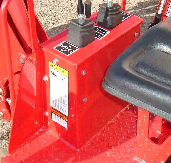
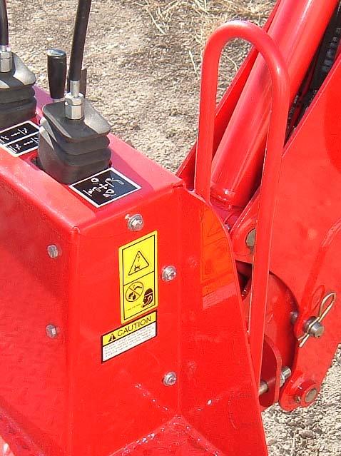
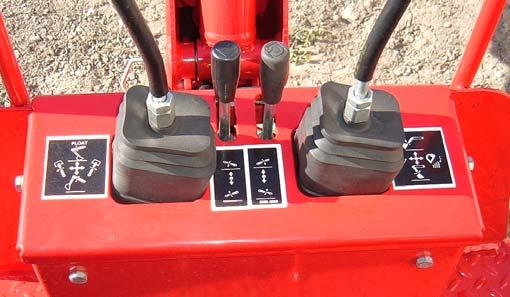
Dedicated hydraulic valve with dual plus axis levers. Formed console gives unit a modern appearance and allows improved comfort to operator. Double acting cylinders
♦ Bucket = 2.00” Bore x 1.12” Rod
♦ Lift = 2.50” Bore x 1.25” Rod
♦ Dipper = 2.25” Bore x 1.12” Rod
♦ Stabilizer = 2.25” Bore x 1.12” Rod
♦ Swing = 2.50” Bore x 1.12” Rod
Cushioned, orificed and port reliefs are designed into the swing cylinder circuit allowing for smooth operation of backhoe.
Heavy duty swing frame.
Backhoe valve is positioned low to operator. This allows less heat and noise to be transferred into operator’s area.
Standard duty buckets with heavy duty cutting edges. Buckets are available in three sizes: (10”, 12” and 16” for 1815/1816 with 1710A) and (four sizes: 10”, 12”, 16", and 20” for 2415/2516 with 1710B and 2015/2216 with 1710C).
IMPORTANT: Never use 20” bucket on 1710A on 1815 tractor. Failure to follow these instructions could cause instability of unit and/or unacceptable axle loading.
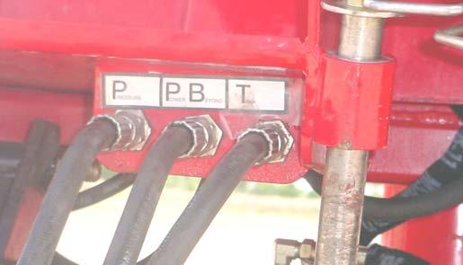
SAE O-ring, Flat face O-ring, and JIC hydraulic connections are used on this unit to reduce potential hydraulic leaks.
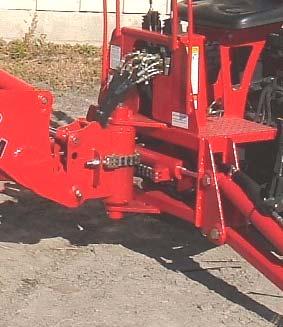
Under frame Mounting System mounts to the center and rear end of tractor. Some 3-point linkages must be removed with backhoe installed. When backhoe is parked 3-point components can be reinstalled. Quick on and off: pull two quick pins and back away. (See detailed instructions in this manual)
High strength steel with box tubing dipper assembly. High back comfortable seat.
1.2. Specifications
Following specifications are based on lower swing pivot bolt being 11” off of the ground. See photo below. Specifications will vary depending on tractor model and wheel size it is equipped with. Specifications are provided for general use only. Specifications are subject to change without notification.
CAUTION: DO NOT operate backhoe without front loader and Roll Over Protection System (ROPS) mounted on tractor. Loader provides front ballast for better steering control and makes tractor/backhoe more stable during backhoe operation.
2. INTRODUCTION
This manual provides safety, installation, operation, maintenance, removing, storing, and reinstalling instructions for your new backhoe. Your backhoe has been designed to give many years of satisfactory service. Successful operation and long life of the backhoe depends, of course, on proper operation and care. Please read this manual carefully and follow the instructions. Correct operation and maintenance will save much time and expense. OBSERVE and follow all CAUTION, WARNING, and DANGER instructions to help prevent serious injury and damage to the backhoe.
The reference to right hand (RH) and left hand (LH) used in this manual refers to the position when seated in the backhoe seat and facing toward backhoe.
If, at any time, you have a service problem with your backhoe or need new parts, contact your local Mahindra dealer. Your dealer will need the backhoe model number and serial number to give you prompt, efficient service. The serial number plate is located on left front hand side of backhoe.
Mahindra Backhoe Serial Number Information
BACKHOE SERIAL NUMBER
DATE PURCHASED
DEALER NAME
TELEPHONE NUMBER
3. BACKHOE COMPONENTS
Read entire instructions before beginning to install the backhoe. Serious injury and machine damage may be prevented if you read and understand these instructions and special safety messages.
Backhoe Components
Throughout this manual, reference is made to various backhoe components. The purpose of this page is to acquaint you with the various names of these components. This knowledge will be helpful when reading through this manual or when ordering service parts.

4. INSTALLATION INSTRUCTIONS ALL MODELS
CAUTION: DO NOT operate backhoe without front loader and Roll Over Protection System (ROPS) mounted on tractor. Loader provides front ballast for better steering control and makes tractor/backhoe more stable during backhoe operation. Read entire instructions before beginning to install the loader. Serious injury and machine damage may be prevented if you read and understand these instructions and special safety messages. When you are in the backhoe seat looking toward backhoe, the RH and LH sides of the backhoe are the same as your right hand and left hand.
4.1. Backhoe And Tractor Models
Model 1710A Backhoe is to be used on Mahindra 1815/1816 Tractors. Model 1710B Backhoe is to be used on Mahindra 2415/2516 Tractors. Model 1710C Backhoe is to be used on Mahindra 2015/2216 Tractors.
4.2. Tractor Preparation-All Models
4.2.1. Tractor Tires
Use tires of equal size and maintain equal pressure in each tire. The pressure of the tractor tires must be increased to the maximum approved pressure recommended by the tire manufacturer to compensate for additional load placed on the tires with the front end loader and backhoe.
4.2.2. Tractor Ballast
The front end loader counterbalances tractor for maximum backhoe capacity and is required for safe backhoe operation. With front end loader installed, tractor maintains better traction and steering control and backhoe is more stable and efficient during operation.
IMPORTANT: Do not exceed the maximum load capacity of the tires on your tractor. See Tire and Wheel Specifications in tractor Operator Manual for more information.
4.2.3. Position the backhoe and tractor on hard level surface during backhoe installation.
4.2.4. Remove all backhoe, backhoe subframe/brackets, and misc. components from shipping packaging. WARNING: To avoid serious injury or death: Read before cutting bands or removing attaching straps. The backhoe may shift during shipping and handling, making it unstable on the pallet. Support backhoe with an overhead hoist or other suitable means prior to removing bands or attaching straps securing backhoe to pallet. Failure to do so could result in accidental tip-over of backhoe that could cause serious injury to you and/or bystanders.
CAUTION: Lift and support all backhoe components safely.
4.1. 1710A and 1710B on tractor models 1815/1816 and 2415/2516: Remove the following equipment from tractor:
Remove belly mower (if so equipped) to allow backhoe to be installed.
Park front end loader (if so equipped) during backhoe installation.
Remove Loader Rear Ballast. Remove Drawbar.
Remove Slow Moving Vehicle Sign and bracket. Remove 3-Point upper link. Adjust tractor seat forward so there will be clearance between tractor seat and backhoe seat.
Note: When backhoe attachment is parked from tractor, reinstall loader rear ballast, drawbar, Slow Moving Vehicle Sign and bracket, and 3-point upper link to tractor before operating.
Identify Backhoe Subframe kit using illustration and measurements shown.
1710A
Remove Slow Moving Vehicle Sign and bracket, 3-Point Upper Link, Drawbar, 11.06” 5.50”
1710B
10.77”
Installation Instructions For Backhoe Model 1710a
4.2.5. Remove tractor rear drawbar hardware and install rear backhoe bracket to rear drawbar area of tractor using hex head cap screw 12-1.75 x 45mm, ½” lockwasher and ½” hardened flatwasher in top two holes and hex head cap screw 12-1.75 x 75mm, ½” lockwasher and ½” hardened flatwasher in bottom two holes as shown.
Hex Head Cap Screw 12-1.75 x 45mm, ½” lockwasher and ½” hardened flatwasher in top two holes, torque these bolts to 62-69 ft. lbs.
Hex Head Cap Screw 12-1.75 x 75mm, ½” lockwasher and ½” hardened flatwasher in bottom two holes, torque these bolts to 62-69 ft. lbs.
Rear Backhoe Bracket

4.2.6. BACKHOE WITH LOADER: Remove loader cross member assembly and hardware from between RH and LH loader center bracket assemblies, if preinstalled. Position backhoe front mount assembly between RH and LH loader center mount assemblies as shown. Secure using original loader crossmember hardware previously removed. IMPORTANT:Do not tighten these bolts at this time. These bolts will need to be tightened after backhoe subframe is mounted.
Hex Head Cap Screw ½”-13 x 1.75”, Stover Hex Locknut (loader supplied), 2 places each side
RH Center Loader Bracket Assembly
Backhoe Front Mount Assembly
Installation Instructions For Backhoe Model 1710b
4.2.7. Remove tractor rear drawbar hardware and install rear backhoe bracket to drawbar area of tractor using hex head cap screw 14-2 x 35mm, 9/16” lockwasher and 9/16” hardened flatwasher 4 places as shown.
Hex Head Cap Screw 14-2 x 35mm, 9/16” Lockwasher, 9/16” Hardened Flatwasher, 4 places, torque these bolts to 87-98 ft. lbs.
Backhoe Rear Bracket

4.2.8. BACKHOE WITH LOADER: Remove loader cross member assembly and hardware from between RH and LH loader rear rails and RH and LH loader center bracket assemblies, if preinstalled. Position backhoe front mount assembly between RH and LH loader rear rails and RH and LH loader center mount assemblies as shown. Secure using original loader crossmember hardware previously removed. Do not tighten these bolts at this time. These bolts will need to be tightened after backhoe subframe is mounted.
Hex Head Cap Screw ½”-13 x 2.25”, Stover Hex Locknut (loader supplied), 2 places each side
RH Center Bracket Assembly
RH Rear Rail
Backhoe Front Mount Assembly