
6 minute read
2.13.1 NAME OF OUTRIGGER COMPONENTS

(1) Outrigger rotary
(2) Outrigger cylinder
(3) Outrigger base
(4) Outrigger top
(5) Inner box
(6) Outrigger adapter (Tray)
2.13.2 OUTRIGGER SET UP OPERATION
(7) Inner box position pin
(8) Snap pin
(9) Snap pin
(10) Outrigger top position pin
(11) Stay (Damper type)
(12) Rotary position pin
[1] TASKS TO BE PERFORMED UPON ENGINE STOP
To install in "Outriggers MAX Extention" position, locations of holes for position pins (12) in outrigger rotaries (1) are different between outriggers [(1)] and [(4)]) and (outriggers [(2)] and [(3)]).
Please read description in this section thoroughly so that you can install outriggers securely. This section describes the practice to install outriggers in "Outriggers MAX Extension" position.
There are four outriggers installed on the machine.
Installation of outriggers is achieved in the same way except for the setting positions of outrigger rotaries (1).
The setting positions of outrigger rotaries (1) are different between outriggers [(1)] and [(4)]) and outriggers [(2)] and [(3)].
Read the descriptions in the following pages so that outriggers are correctly installed.

Applicable to “outrigger (1) and (4)”
1. Pull the position pin (12) out of the outrigger rotary (1) and rotate the outrigger rotary outward.
2.Rotate the outrigger rotary (1) so that the sticker "Standard/Stow" affixed to its side and the sticker "Standard" affixed to the side of frame are aligned.
3.Insert positioning pin (12) to the aligned hole of the outrigger rotary (1)
Applicable to “outrigger (2) and (3)”
4. Pull the position pin (12) out of the outrigger rotary (1) and rotate the outrigger rotary outward.
5 Rotate the outrigger rotary (1) so that the sticker "Standard" affixed to its side and the sticker "Standard" affixed to the side of frame are aligned.
6 Insert positioning pin (12) to the aligned hole of the outrigger rotary (1)
Caution
• Each position pin (12) contains a chain which prevents the pin from going missing. Make sure that such chains are not entangled with the frame. If so, it may result that position pins (12) are not inserted completely to the end of the hole in the outrigger rotary (1). Due to such an instable condition, that pin is likely to come out from the hole easily.
• Stickers in outrigger rotaries and frames should match as follows when outriggers are extended to the standard position: "Standard/Stow" and "Standard" for outriggers [(1)] and [(4)], while "Standard" and "Standard" for outriggers [(2)] and [(3)]


7. Pull out the snap pin (9) from the position pin (10) of the outrigger base (3) to pull out the position pin (10).
8. Lift up the outrigger top (4) to align the hole in the outrigger top (4) and the hole of the top position in the outrigger base (3) (as indicated by the sticker, ”Extend to max.”).
Notes
Location of the hole of the top position in the outrigger base (3) is identifiable by the sticker, ”Extend to max.”
9. Insert the position pin (10) to hole of the top position in the outrigger base (3) (as indicated by the sticker,”Extend to max.”) and secure it with a snap pin (9) at the end.
Notes
When the position pin is inserted into any hole in the outrigger base (3) to which a sticker, ”Other than max.” is affixed, the crane operation shall be limited in accordance with the ”Rated Total Load Chart with outrigger extended to other than maximum”
10. Pull the snap pin (8) out from the position pin (7) of the outrigger top (4) to pull out the position pin (7).


11. Pull out the outrigger inner box (5) from the outrigger top (4) and align the hole in the outrigger top (4) and the hole in the root position of the outrigger inner box (5).
Notes
The hole in the root position of the outrigger inner box (5) is a hole which matches the hole in the outrigger top (4) when a "MAX" sticker which is affixed to the side of the inner box is completely exposed


12. Insert the position pin (7) to the hole of the outrigger top (4) then secure it with the snap pin (8).
Notes
When the pin is inserted into any hole other than the "MAX" of the inner box, the crane operation shall be limited in accordance with the ”Rated Total Load Chart with outrigger extended to other than maximum”
13. When all the preparations as above complete, check again that each position pin and such is correctly inserted and secured by a snap pin or such.

[2] TASKS TO BE PERFORMED AFTER STARTING THE ENGINE
• The overturning alarm buzzer sounds if the machine tilts for “3 degrees” or more when setting the outriggers. Operate the outrigger switches and adjust the machine to be leveled until the alarm buzzer stops.
• Avoid using the Outrigger collective setting switch where the installation height of each outrigger is different. Its use may cause the machine to incline or fall over.
Caution
Once 4 outriggers touch the ground consistently, use the Outrigger collective setting switch to facilitate smooth elevation of the machine.
1. See “Operation 2.2 Starting the Engine” to start the engine.


2. Pull up the lock lever (6) before pressing the whole lever stand (7) down to the "Crane Operation Position", then release the lock lever (6).
3. Move forward to the Crane Operation Unit.
4. Turn the acceleration lever to left or right side and change the engine speed to medium speed less than.

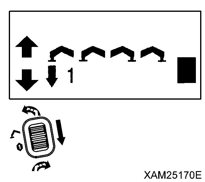
5. Open the outrigger switch cover and turn the Outrigger collective setting switch (16) to the OUT position. 4 outrigger cylinders start extending. Just before 4 Outrigger adapters (Trays) touch the surface of the ground, release the Outrigger collective setting switch (16) to the NEUTRAL position, once.

When operating two individual outrigger operation switches at the same time, choose two front switches (outrigger (2) and (3)) or two rear switches (outrigger (1) and (4)). Operating two left or right switches at the same time will suddenly raise two outriggers on one side, causing the machine to overturn.
6. Check the number of the outrigger which has not yet touched the ground and assure the number in the control panel, to determine the outrigger number to operate.

7. Open the outrigger switch cover and turn the Outrigger individual setting switch (15) respectively or 2 switches at the same time to the OUT position, so that all the 4 Outrigger adapters (Trays) touch the surface of the ground consistently.

8. After all the 4 Outrigger adapters (Trays) touch the surface of the ground consistently, turn the Outrigger collective setting switch (16) to the OUT position
4 outrigger cylinders start extending. When the crane body is lifted up as high as approximately 50mm, release the Outrigger collective setting switch (16) to the NEUTRAL position.
9. When the machine was raised to about 50 mm above the ground, operate the outrigger individual operation switches while checking the position of the bubble in the level to adjust the machine to be leveled.
10. After setting the outriggers, operate all the outrigger operation switches to the NEUTRAL position.

11. When the outrigger installation as above completes, check again that all the position pins are correctly inserted and secured to prevent them from slipping out.
2.14 CAUTIONS BEFORE CRANE OPERATION
• Not observing these cautions before operation may result in serious accidents.
• It takes a certain moment for the over hoist detector to effect automatic interruption after it detects an over hoisting condition. Therefore, when the Over hoist and moment limiter alarm buzzer beeps, always release all of the operation levers to the NEUTRAL position. Otherwise, when operations as below are continued, such operation may not stop.

• Winch lever "UP" operation, Boom telescoping lever "Extending"operation and Boom derricking lever "Raise" operation.
• Verify that the emergency stop cancel switch, boom stowing switch, and hook stowing switch are at the OFF position. If these switches are at ON position, the operations will not stop.

• Over hoisting the hook block will activate the alarm buzzer of the over hoist detector and the operation stops
When the alarm buzzer sounds, release your hand immediately from the winch lever (3) to the NEUTRAL position to stop raising the hook.
Then, operate the winch lever (3) to “DOWN” (push forward) side to lower the hook block.
• Extending the boom will hoist the hook block, activating the alarm buzzer of the over hoist detector and the operation stops. When the alarm buzzer sounds, release your hand immediately from the boom telescoping lever (2) to the NEUTRAL position to stop extending the boom. Then, operate the boom telescoping lever (2) to “RETRACT” (pull toward you) side to retract the boom.


• Raising the boom will hoist the hook block, activating the alarm buzzer of the over hoist detector and the operation stops. When the alarm buzzer sounds, release your hand immediately from the boom derricking lever (4) to the NEUTRAL position to stop raising the boom.
Then, operate the boom derricking lever (4) to “DOWN” (push forward) side to lower the boom.

• Use the horn switch to honk the horn to notify the people around of the danger during the crane operation.
• Verify that all the outriggers are extended and set


