
5 minute read
1.3 CRANE OPERATION UNIT

(1) Slewing lever
(2) Boom telescoping lever
(3) Winch lever
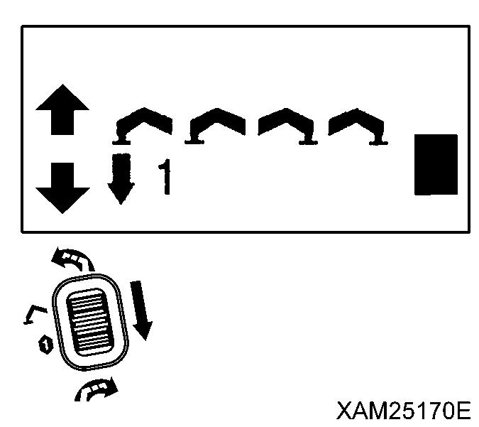
(4) Boom derricking lever
(5) Acceleration lever
(6) Headlight
(7) Moment limiter display panel
(8) Over hoist and moment limiter alarm buzzer
(9) Emergency stop cancel switch
(10) Boom stowing switch
(11) Level
(12) Working status lamps
(13) Engine emergency stop switch
(14) Auxiliary starter switch
(15) Hook stowing switch
(16) Horn switch
(17) Outrigger individual setting switch
(a) Outrigger (1) setting switch
(b) Outrigger (2) setting switch
(c) Outrigger (3) setting switch
(d) Outrigger (4) setting switch
(18) Outrigger collective setting switch
1.3.1 DESCRIPTION OF EACH LEVER
[1] ACCELERATION LEVER (5)
Use the lever to adjust the engine speed or output.
• Low idling: Turn the lever to counter clockwise.
• Full speed: Turn the lever to clockwise.
Notes
• At the desired engine speed for your work, release the lever. It will stop at that position.
• Acceleration lever is also provided on the travelling control unit.
[2] SLEWING LEVER (1)
Use the lever to slew the crane boom and post.
• Slew counter clockwise: Push the lever forward (Left).

• Neutral: Release your hand from the lever. The lever returns to the NEUTRAL position and the slewing stops.
• Slew clockwise: Pull the lever toward you (Right).
[3] BOOM TELESCOPING LEVER (2)
Use this lever for telescoping the crane boom.
• Extend: Push the lever forward (Extend).

• Neutral: Release your hand from the lever. The lever returns to the NEUTRAL position and the boom telescoping stops.
• Retract: Pull the lever toward you (Retract).
[4] WINCH LEVER (3)
Use this lever to raise/lower the hook block of the crane.
• Lower: Push the lever forward (Down).
• Neutral: Release your hand from the lever. The lever returns to the NEUTRAL position and the machine automatically brakes. The lowering/raising of the hook block stops.
• Raise: Pull the lever toward you (Up).
[5] BOOM DERRICKING LEVER (4)
Use this lever for derricking the crane boom.
• Lower: Push the lever forward (Lower).


• Neutral: Release your hand from the lever. The lever returns to the NEUTRAL position and the boom derricking stops.
• Raise: Pull the lever toward you (Raise).

1.3.2 DESCRIPTION OF EACH SWITCH
[1] EMERGENCY STOP CANCEL SWITCH (9)
• Do not turn the emergency stop cancel switch to the ON (cancel) position except in a machine failure condition or when conducting a load test. When the emergency stop cancel switch is in ON position, the moment limiter functions are not available. Any crane operation in such conditions will result in dropping of hoisted load, breakage of crane boom, and/or crane tipping due to over load, and may cause a serious accident resulting in death or serious injury. Key for the switch must be detached during normal operations.
• Do not turn the emergency stop cancel switch to the ON (cancel) position when stowing the hook.

The winch wire rope may be cut causing the hook to fall on or damage the boom. Use the hook stowing switch when stowing the hook.
Use the emergency stop cancel switch only for the purpose to release emergency stop when the safety device of the Crane seems to have a failure, or when a load test is required. Open the cover when using the switch.
• ON (Clear): Insert the key into the switch. Turn the key clockwise and retain the key at that position. The activation stop function is cleared while the key is maintained at the ON position.
• OFF (Auto): Insert the key into the switch and turn the key counterclockwise. The activation stop functions. The key can be removed or inserted at this position.

[2] BOOM STOWING SWITCH (10)
• The boom stowing switch cancels the auto-stop function of the lower-limit detecting interlock device during the boom “lowering” operation. Operate the boom derricking lever carefully when stowing the boom. Pay sufficient attention not to let the boom collide with the machine body.
• Use the boom stowing switch only when stowing the boom.
Use this switch to stow the boom
• ON: Keep pushing the switch downward and operate the boom derricking lever to “LOWER” side. The boom lowers and can be stowed.
• OFF: Release your finger from the switch. The switch returns to the original position and the auto-stop function of the lower-limit detecting interlock device will be activated.
[3] ENGINE EMERGENCY STOP SWITCH (13)

Use this switch in case of an error in the machine to stop the machine for emergency.
• ON: Press the switch. The engine stops.
• OFF: Turn the switch clockwise (direction of the arrow in the right figure). The switch returns to the original position.
Notes
When restarting the engine after emergency stop, be sure to turn the engine emergency stop switch to the OFF position before starting the engine.


[4] AUXILIARY STARTER SWITCH (14) CAUTION
The auxiliary starter switch functions only while main starter switch at travel control is in ON position. To start-up engine using the auxiliary starter switch, the main starter switch must remain at ON position.
Use this switch to start and stop the engine.
• START: Keep pushing the switch upward. The engine starts. When the engine has started, release your finger from the switch
• Neutral: Release your finger from the switch. The switch returns to the NEUTRAL position.
• STOP: Keep pushing the switch downward. The engine stops. When the engine has stopped, release your finger from the switch
[5] HOOK STOWING SWITCH (15)
• The hook stowing switch cancels the auto-stop function of the over hoist detector. Operate the winch lever carefully when stowing the hook block. Pay sufficient attention not to let the hook block collide with the boom.
• Use this switch only when stowing the hook block.
• When the hook block is stowed in the hook block holder and the wire rope slacking is eliminated, turn OFF the hook stowing switch without delay. Otherwise, the wire rope will be over-wound which causes it to wedge into the winch drum.
Use this switch to stow the hook block at the lower top of the machine
• ON: Keep pushing the switch upward. The over hoist detector is released and the hook block is wound up slower than the normal operation mode, so that it is stowed in the hook holder.
• OFF: Release your finger from the switch. The switch returns to the original position and the auto-stop function of the over hoist detector will be activated.
[6] HORN SWITCH (16)
Use this switch to honk the horn.
• Honking the horn: Press the switch.
Notes
• The horn will stop when you release your finger from the switch.
• The horn switch is provided on the travelling control side as well.
[7] OUTRIGGER SETTING SWITCH (17), (18)
Use these switches to install or stow each of 4 [(1) to (4)] outriggers.
Outrigger setting switch includes 4 Outrigger individual setting switches (17) and 1 Outrigger collective setting switch (18).
4 Outrigger individual setting switches enable to control each of 4 [(1) to (4)] outriggers separately.

In contrast, the Outrigger collective setting switch enables to control all the 4 [(1) to (4)] outriggers simultaneously.

• IN : Turn the switch upward.
Outrigger cylinder retracts and the outrigger is stowed.
• Neutral: Release your finger from the switch.
The swtich returns to its NEUTRAL postion and extending or retracting of the outrigger is interrupted.
• OUT : Turn the switch downward.
Outrigger cylinder extends and the outrigger is installed.
[8] LEVEL (11)
When installing the outrigger, make adjustments while looking at the level so that the machine body will be leveled. Performing the crane operation with the body tilted will cause overturning.
This device indicates how much the machine body is tilted. The bubble position shows how much the machine is tilted in which direction.

Use this device to verify that the machine is leveled when setting the outriggers

[9] WORKING STATUS LAMPS (12)
Color of each working status lamp shows current load factor (ratio of the hoisting load weight to rated total load).
• Red lamp (12A) shows LIMIT WARNING where the load factor is 100 % or higher than the rated total load, when it is lit.
• Yellow lamp (12B) shows PRE-WARNING where the load factor is 90 to less than 100 % of the “rated total load, when it is lit.
• Green lamp (12C) shows SAFETY ZONE where the load factor is less than 90 % of the rated total load, when it is lit.
12A: Red lamp 12B: Yellow lamp
12C: Green lamp


