5-101.bk Page 17 Friday, March 17, 2006 11:05 AM
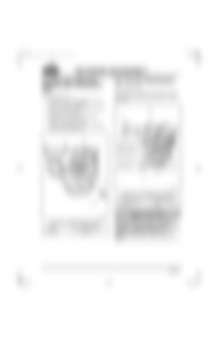
200 ENGINE DISASSEMBLY [212 RB & RH] VIBRATION DAMPER AND CRANKSHAFT HUB Refer to Figure 4-19. 1. Remove six mounting capscrews (4) and turnover bracket, if equipped.
[261 CK] AIR COMPRESSOR Refer to Figure 4-20. Disconnect two coolant lines (1 and 4) from the air compressor head (2) at the fittings. Tag and cap lines.
2. Remove vibration damper (3) and fan belt drive pulley (1) together.
2 1
3. Using a 1-7/16 inch wrench, remove crankshaft hub capscrew (2). 4. Using a suitable puller such as J 24420-C, remove the crankshaft hub. 2 1
3 4 5 3 200258a
Figure 4-20 — Air Compressor Connections 1. Coolant supply line 2. Air compressor head 3. Capscrew
4
4. Coolant return line 5. Air governor mounting flange
200359a
Figure 4-19 — Vibration Damper Removal 1. Pulley 2. Capscrew
3. Vibration damper 4. Capscrew
The air compressor is heavy. Lifting the air compressor may require the help of an assistant or suitable lifting device. Attempting to lift the compressor without such assistance may result in severe personal injury.
Page 4-17
