5-101.bk Page 55 Friday, March 17, 2006 11:05 AM
200 BENCH PROCEDURES 13 10
12
15
14
11
9 8 16 7
6
18 17
5
1
2
3
4
19
20 24
27
23 22 21
25 26
200556a
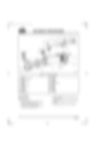
Figure 5-67 — Oil Cooler Assembly 1. Gasket 2. Coolant outlet end cap 3. O-ring 4. Mounting flange 5. Clamps 6. Coupler 7. Gasket or O-ring 8. Washer 9. Capscrew 10. Oil outlet tube 11. O-ring 12. Capscrew 13. Washer 14. Oil supply head
Disassembly Refer to Figure 5-67. 1. Remove coolant inlet end cap (20) by removing six capscrews (19). 2. Remove coolant outlet end cap (2) by removing six capscrews (26).
15. Capscrew 16. Washer 17. O-ring 18. Pipe plug 19. Capscrew 20. Coolant inlet cap 21. Gasket 22. Bundle 23. Gasket 24. Housing 25. Gasket 26. Capscrew 27. Capscrew
3. Remove bundle (22) from coolant inlet end of housing (24). 4. Remove O-ring (3) from coolant outlet end of housing. 5. Clean gasket material from all surfaces.
Page 5-55
