5-101.bk Page 49 Friday, March 17, 2006 11:05 AM
200 BENCH PROCEDURES
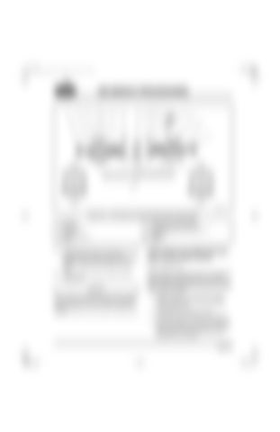
Figure 5-62 — Valve Rocker Arm Shaft Assembly (Without Engine Brake) 1. Snap ring 2. Flat spring 3. Inlet rocker arm 4. Brackets 5. Exhaust rocker arm 6. Spring
7. Locating screw and lock washer 8. Bracket with center threaded hole 9. Standard adjusting screws and jam nuts 10. Capscrews 11. Washers 12. Shaft
19. Install flat spring (2) and snap ring (1) on end of shaft. Some rocker arm shafts are equipped with threaded plugs and aluminum washers instead of flat springs and snap rings.
Valve Rocker Arm Shaft Assembly (with Jacobs Engine Brake)
20. Check all rocker arms to make sure they rotate freely.
The assembly procedure for rocker arm shaft with engine brake is described below. The engine brake arrangement includes exhaust valve rocker arms with lash adjusters and a solenoid mounted in the rocker arm shaft.
Valve rocker arm shaft assembly will be installed during engine assembly by inserting capscrews (10) and washers (11) into holes in brackets (4) and (8).
1. Position shaft (11) so that the oil supply screw locating hole is in line with bracket locating screw hole.
Refer to Figure 5-63.
2. The offset side of bracket must be positioned toward the right side of engine. 3. Assemble bracket with center threaded hole (8) on press table. Press shaft into bracket until oil hole in shaft is positioned under threaded hole in bracket. Page 5-49
