Control and operation
Operating manual
Hydraulic removable counterweight
Notice! When an additional counterweight 8 is installed, the screws 12 are no longer accessible.
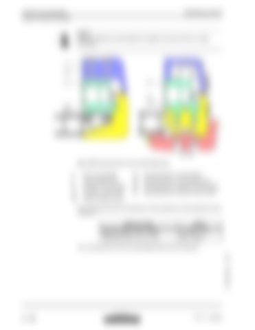
Fig. 3-150 Mounting bolts of the counterweight parts 2
Main counterweight
12
Mounting bolts for counterweight
3
Counterweight shell
13
Mounting bolts for counterweight shell
8 11
Additional counterweight counterw. carrier frame
18 21
Mounting bolts for additional counterweight Mounting bolts for counterw.carrier frame
24
Uppercarriage structure The mounting bolts 18 of the optionally mounted additional counterweight 8 must be torqued to:: Machine model
R974C
Bolts 18: Number / Size - Quality
4 X / M42 - 10,9
Tightening torque: N.m / (ft . lbs)
4900 / (3640)
The mounting bolts 13 of the counterweight shell 3 must be torqued to
copyright by
3 - 166
MJFCIFSS
R 974 C / 10069856


